

Page 1
USER MANUAL
T013 TREADMILL WITH BLUETOOTH
IMPORTANT: Read all instructions carefully before using this product. Retain owner’s manual for
future reference. For customer service, please contact: [email protected]
Page 2
WARNING: This product can expose you to one or more chemicals known
to the State of California to cause cancer and birth defects or reproductive harm.
For more information go to www.P65Warnings.ca.gov.
IMPORTANT SAFETY INSTRUCTIONS
When using an electrical appliance, basic precautions should always be followed, including
the following:
Read all instructions before using this treadmill.
DANGER– To reduce the risk of electrical shock:
1. Always unplug this appliance from the electrical outlet immediately after using and before
cleaning.
WARNING – To reduce the risk of burns, fire, electric shock, or injury to persons:
1. The treadmill should never be left unattended when plugged in. Unplug from outlet when
not in use and before putting on or taking off parts.
2. Use this treadmill only for its intended use as described in this manual. Do not use
attachments not recommended by the manufacturer.
3. Never operate this treadmill if it has a damaged cord or plug, is not working properly, has
been dropped or damaged.
4. Keep the cord away from heated surfaces.
5. Never operate the treadmill with the air openings blocked. Keep the air openings free of
lint, hair, and the like.
6. Never drop or insert any object into any opening.
7. Do not use outdoors.
8. Do not operate where aerosol (spray) products are being used or where oxygen is being
administered.
9. To disconnect, turn the treadmill off, then remove plug from outlet.
10. Connect this treadmill to a properly grounded outlet only. See grounding instructions.
CAUTION: Risk of Injury to Persons:
To avoid injury, use extreme caution when stepping onto or off of a moving belt. Read
Instruction Manual Before Using.
SAVE THESE INSTRUCTIONS
1
Page 3

IMPORTANT SAFETY INFORMATION
We thank you for choosing our product. It is important to read this entire manual before
assembling and using the equipment. It is your responsibility to ensure that all users of the
equipment are informed of all warnings and precautions.
1. Before starting any exercise program you should consult your physician to determine if
you have any medical or physical conditions that could put your health and safety at risk or
prevent you from using the equipment properly. Your physician’s advice is essential if you
are taking any medication that may affect your heart rate, blood pressure, or cholesterol
level.
2. Be aware of your body’s signals. Incorrect or excessive exercise can damage your health.
Stop exercising if you experience any of the following symptoms: pain, tightness in your
chest, irregular heartbeat, shortness of breath, lightheadedness, dizziness, or nausea. If
you do experience any of these conditions, consult your physician before continuing with
your exercise program.
3. Keep children and pets away from the equipment. The equipment is designed for adult use
only.
4. Use the equipment on a solid, flat level surface with a protective cover for your floor or
carpet. To ensure safety, the equipment should have at least 4 feet of free space all around
it.
5. Ensure that all nuts and bolts are securely tightened before using the equipment. Check
equipment regularly for damage and/or wear and tear.
6. We recommend that you lubricate all moving parts monthly.
7. Always use the equipment as indicated. If you find any defective components while
assembling or checking the equipment, or if you hear any unusual noises coming from the
equipment during exercise, stop using the equipment immediately and don’t use the
equipment until the problem has been rectified.
8. Wear suitable clothing while using the equipment. Avoid wearing loose clothing that may
become entangled in the equipment.
9. Do not place fingers or objects into the moving parts of the equipment.
10. The maximum weight capacity of this unit is 220 pounds.
11. This equipment is not suitable for therapeutic use.
12. Move with caution when lifting and moving the equipment. Always use proper lifting
technique and seek assistance if necessary.
13. Your product is intended for use in cool, dry conditions. You should avoid storage in
extreme cold, hot, or damp areas as this may lead to corrosion and other related
problems.
14. This equipment is designed for indoor household use only! It is not intended for
commercial use!
2
Page 4
IMPORTANT OPERATING INSTRUCTIONS
1. Insert the power plug directly into the socket.
2. Read the manual before operating the equipment.
3. Changes in speed do not occur immediately. Set your desired speed using the
adjustment keys on the main console. The speed will increase gradually.
4. While on the treadmill, move with caution as distractions may cause you to lose
balance and stray from walking in the center of the belt which may result in serious
injury.
5. This unit starts at a very low speed. To begin use, hold onto the handrails and stand
on the side rails while it starts up, then step onto the belt once it’s in motion.
6. Always hold the handrail when making changing settings.
7. A safety key is provided for emergency use. The machine will function only if the
safety key is inserted into the computer console. In case of emergency, remove the
safety key to immediately stop the belt and shut off the treadmill. The display screen
will reset once the safety key is reinserted.
8. The console control keys are precisely set and require very little finger pressure to use.
To avoid damaging these keys, do not use excessive pressure when operating these
controls.
9. This equipment is designed for adult use only! Children should not be allowed to use
or play near this equipment. When present, children should be supervised at all
times by an adult.
10. Women who are pregnant or nursing should consult a physician before attempting to
begin any exercise program.
11. Always stay hydrated during and after exercise.
IMPORTANT NOTE:
The belt must be lubricated before the first use! Please see Page 12 for
instructions on how to properly apply lubricant.
3
Page 5
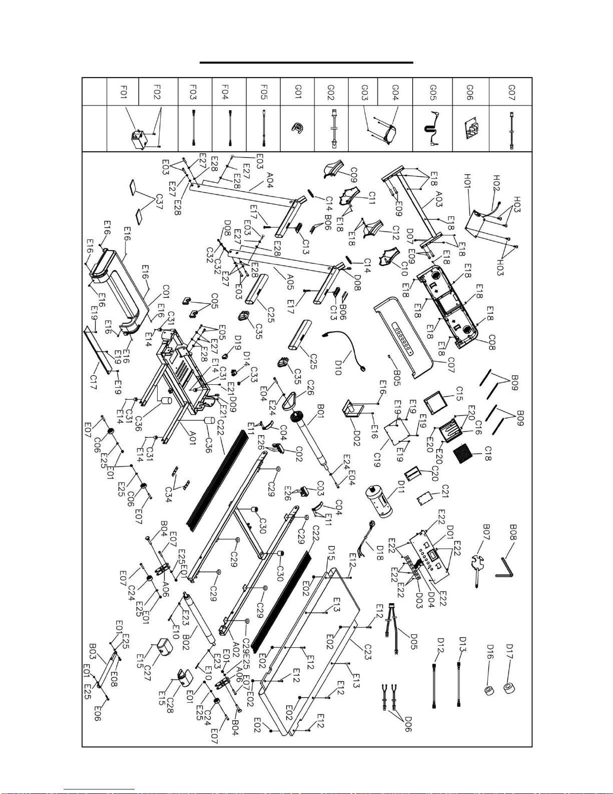
EXPLODED DRAWING
4
Page 6
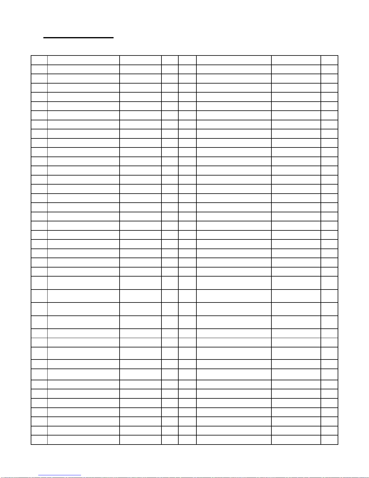
PARTS LIST
No.
Description
Specification
Qty
No.
Description
Specification
Qty
A01
Base Frame
1
D06
Hand Pulse Lower Wire
200MM
2
A02
Main Frame
1
D07
Upper Signal Wire
1
A03
Computer Bracket
1
D08
Middle Signal Wire
1
A04
Left Upright
1
D09
Lower Signal Wire
1
A05
Right Upright
1
D10
Safety Key
1
A06
Adjustable board
2
D11
DC Motor
1
B01
Front Roller
1
D12
AC Single Line
Blue
1
B02
Rear Roller
1
D13
AC Single Line
Brown
1
B03
Air Pressure Cylinder
1
D14
Square Switch
1
B04
Fixing pin
2
D15
Running Deck
1
B05
Safety Key Metal Sheets
1
D16
Magnetic Ring
1
B06
Hand Pulse Metal Sheets
4
D17
Magnetic Core
1
B07
Allen Wrench
5mm
1
D18
Power Wire
1
B08
Spanner w/ screw driver
S=13,14,15
1
D19
Overload Protector
1
B09
Pull Spring
4
E01
Nut
M8
8
C01
Motor Top Cover
1
E02
Nut
M6
6
C02
Left Side Rail Plug
1
E03
Bolt
M8*30
6
C03
Right Side Rail Plug
1
E04
Bolt
M6*15
2
C04
Motor Cover Shutter
2
E05
Bolt
M8*15
2
C05
Plastic Support Plate
2
E06
Bolt
M8*42
1
C06
Moving Wheel
2
E07
Bolt
M8*40
6
C07
Console Top Cover
1
E08
Bolt
M8*30
1
C08
Console Bottom Cover
1
E09
Bolt
M6*35
4
C09
Left Upright Tube Outside
Cover
1
E10
Bolt
M6*55
2
C10
Right Upright Tube
Outside Cover
1
E11
Bolt
M5*12
4
C11
Left Upright Tube Inside
Cover
1
E12
Bolt
M6*32
6
C12
Right Upright Tube Inside
Cover
1
E13
Bolt
M6*25
2
C13
Hand Pulse Plastic Board
2
E14
Screw
ST4.2*19
4
C14
Handrail Decorative Ring
2
E15
Bolt
M5*12
2
C15
Holder Top Cover
1
E16
Bolt
M5*8
10
C16
Holder Bottom Cover
1
E17
Screw
ST4.2*55
2
C17
Front Shutter
1
E18
Screw
ST4.2*12
18
C18
Holder Pad
1
E19
Screw
ST4.2*8
7
C19
Holder Fixed Board
1
E20
Screw
ST3.5*8
4
C20
Holder Sliding Board
1
E21
Screw
ST4.2*12
2
C21
Holder Sliding Board Cover
1
E22
Screw
ST2.9*6.0
10
C22
Side Rail
2
E23
Washer
6
2
C23
Running Belt
1
E24
Big Washer
6
2
C24
Adjustable Wheel
2
E25
Washer
8
8
5
Page 7
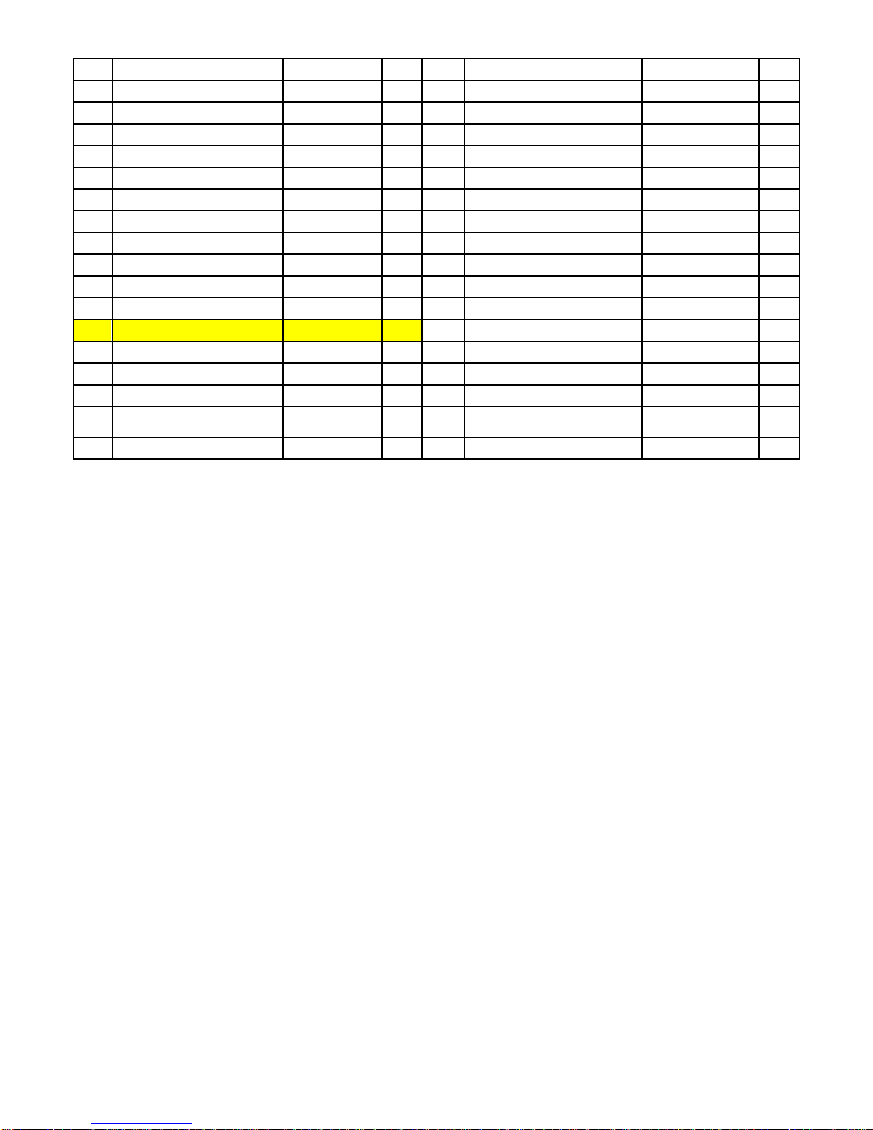
C25
Foam
2
E26
Screw
ST2.9*8.0
4
C26
Motor Belt
1
E27
Spring Washer
8
8
C27
Left End Cap
1
E28
Flat Washer
8
8
C28
Right End Cap
1
F01
Filter
1
C29
Black Cushion
6
F02
Bolt
M5*8
2
C30
Black Cushion
2
F03
AC Single Line
Blue
1
C31
Foot Pad
4
F04
AC Single Line
Brown
1
C32
Ring Protecting Wire Plug
2
F05
Grounding Wire
1
C33
Power Wire Buckle
1
G01
Audio Module Fixing Cap
4
C34
Adjustable Rubber Pad
2
G02
Audio Connecting Line
1
C35
Oval End Cap
2
G03
Screw
ST2.9*6
8
C36
Column Shape Cushion
2
G04
Speaker
2
C37
EVA Pad
2
G05
Mp3 Wire
1
D01
Console
1
G06
Amplifier Board
1
D02
Control Board
1
G07
Power Amplifier Line
1
D03
Button Board
1
H01
Bluetooth Module
1
D04
Button Board Connecting
Wire
1
H02
Bluetooth Power Line
1
D05
Hand Pulse Upper Wire
450MM
1
H03
Screw
ST2.9*81
4
6
Page 8
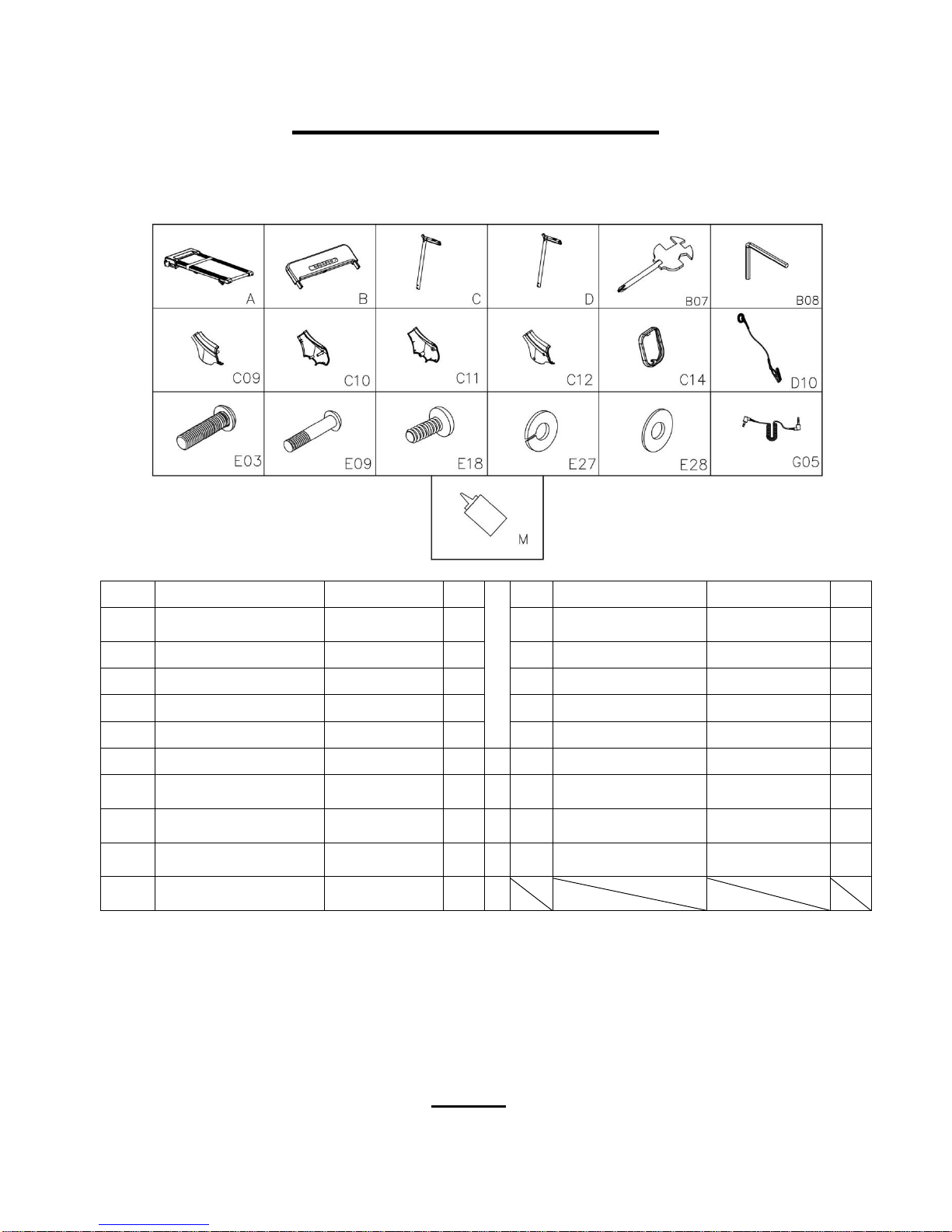
No.
Description
Specification
Qty
No.
Description
Specification
Qty
A
Main Frame
1 C14
Handrail Decorative
Ring
2
B
Console
1
D10
Safety Key
1 C Left Upright Tube
1
E03
Bolt
M8*30
6 D Right Upright Tube
1
E09
Bolt
M6*35
4
B07
Spanner w/ screw driver
S=13,14,15
1
E18
Screw
ST4.2*12
4
B08
Allen wrench
5mm
1 E27
Spring Washer
8
6
C09
Left Upright Tube Outside
Cover
1 E28
Flat Washer
8
6
C10
Right Upright Tube
Outside Cover
1 G05
MP3 Wire
1
C11
Left Upright Tube Inside
Cover
1 M
Lubricant Oil
1
C12
Right Upright Tube Inside
Cover
1
CARTON CONTENTS:
ASSEMBLY HARDWARE
Spanner with Screw Driver (S=13, 14, 15)
TOOLS
Allen Wrench (5mm)
7
Page 9
ASSEMBLY INSTRUCTIONS
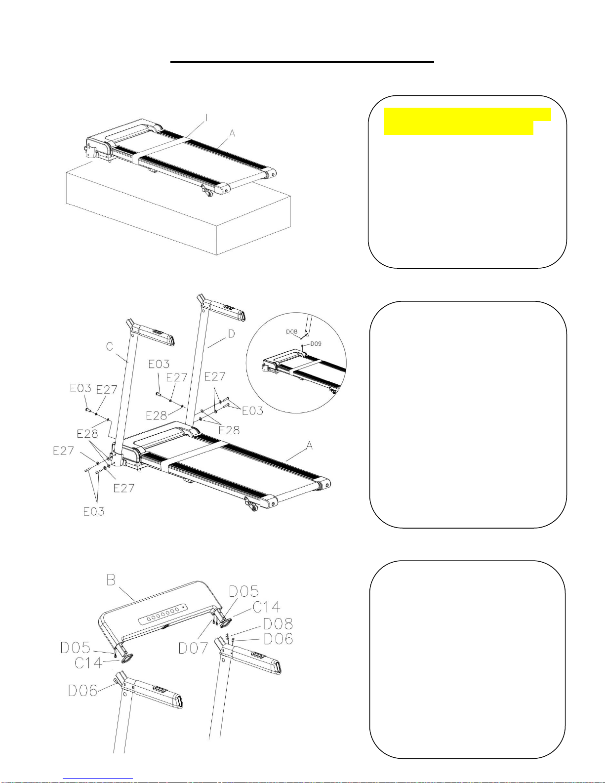
Notice: We recommend having
two people do the assembly.
Open the carton and remove
contents. Place the Main
Frame (No. A) on level ground,
ensure that you have a work
area that is clean and has
adequate space. Do not cut
the Packing Belt (No. I) until
the assembly is complete!
Support the Left & Right
Upright Tubes (No. C and No.
D) with your hands to prevent
them from falling down.
Fix the Left & Right Upright
Tubes (No. C and No. D) to
the Main Frame (No. A) using
6 Bolts (No. E03), 6 Flat
Washers (No. E28) and 6
Spring Washers (No. E27).
Tighten using Allen Wrench
(No. B08).
1. Insert Handrail Decorative
Ring (No. C14) onto the tubes
on Console (No. B).
2. Connect Upper Signal Wire
(No. D07) to Middle Signal
Wire (No. D08).
3. Connect Hand Pulse Lower
Wire (No. D06) to Hand Pulse
Upper Wire (No. D05).
STEP 1:
STEP 2:
STEP 3:
8
Page 10
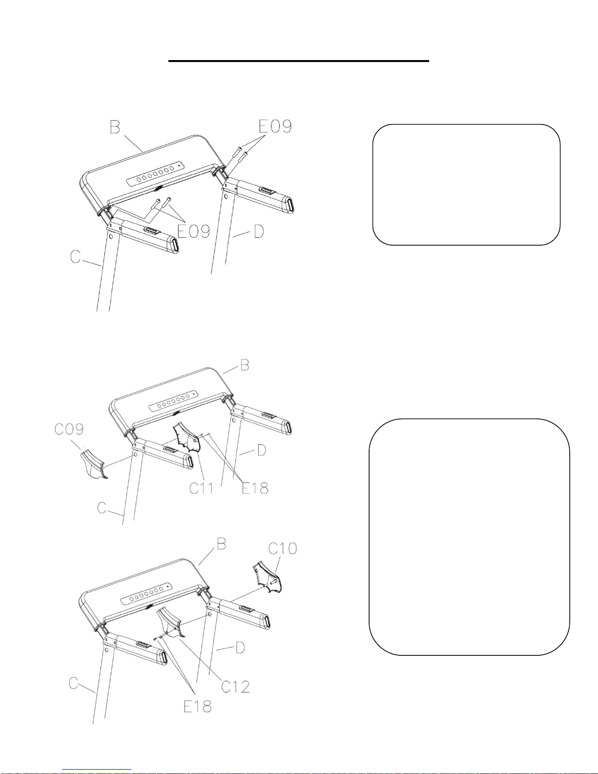
Fix the Console (No. B) to the
Left & Right Upright Tubes
(No. C and D) using 4 Bolts
(No. E09). Tighten using Allen
Wrench (No. B08).
Fix the Left Upright Tube
Outside & Inside Cover (No.
C09 and C11) to the Left
Upright Tubes (No. C) using 2
Screws (No. E18). Tighten
using Spanner with Screw
Driver (No. B07).
Repeat the step above to
assemble the Right Upright
Tube Outside & Inside Cover
(No. C10 and C12) to the Right
Upright Tubes (No. D)
STEP 4:
STEP 5:
ASSEMBLY INSTRUCTIONS
9
Page 11
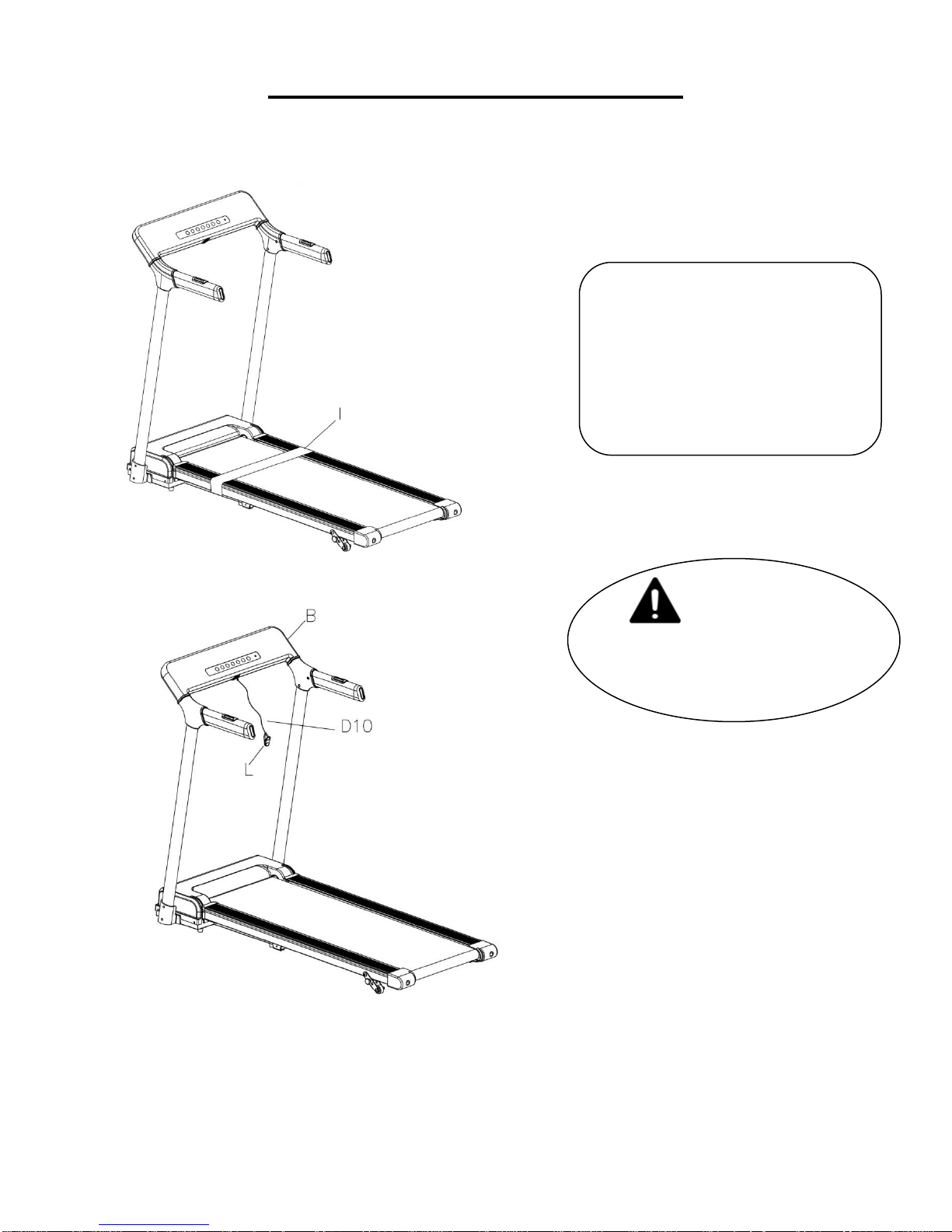
The assembly is now complete!
Now you can cut the Packing
Belt (No. I).
Insert the Safety Key (No.
D10) into the magnetic area of
the Console (No. B)
IMPORTANT NOTE!
You will need to lubricate
your treadmill before the first
use. See Page 12.
STEP 6:
ASSEMBLY INSTRUCTIONS
10
Page 12
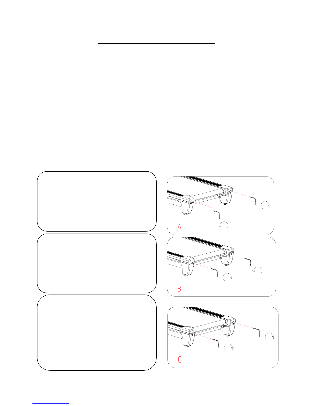
1. If the Running Belt (No. C23)
moves to the right, turn the adjusting
bolt on the right side ¼ turn clockwise,
then turn the left adjustment bolt ¼ turn
counter-clockwise. If the belt does not
move, repeat this step until it centers.
Refer to Figure A.
2. If the Running Belt (No. C23)
moves to the left, turn the adjusting
bolts on the left side ¼ of a turn
clockwise, then turn the right
adjustment bolt ¼ turn
counter-clockwise. If the belt does not
move, repeat this step until it centers.
3. Over time the Running Belt (No.
C23) will loosen. To tighten the belt
turn the Left & Right side adjustment
bolts one full turn clockwise, check
the tension of the belt. Continue this
process until belt is at the correct
tension. Make sure to adjust both
sides equally to ensure correct belt
alignment. Refer to diagram “C”
MAINTENANCE & CARE
General cleaning will help prolong the life and performance of your treadmill. Keep the
unit clean and maintained by dusting the components on a regular basis. Clean both
sides of the running belt to prevent dust from accumulating underneath the belt. Keep
your running shoes clean so that dirt from your shoes does not wear out the running
board and belt. Clean the surface of the running belt with a clean damp cloth.
To better maintain the treadmill and prolong its life it is suggested that the machine be
powered off for 10 minutes every 2 hours and fully powered off whenever not in use.
A loose Running Belt will result in the runner sliding off when running, while too tight of
a Running Belt will result in decrease to the motors performance and also create more
friction between the roller and running belts. The most suitable tightness for the belts is
pulled out 50-75mm from the Running Board.
CENTERING THE RUNNING BELT:
Place the treadmill on level ground and set it at 3-5mph to check if the Running Belt (No.
C23) drifts.
11
Page 13
LUBRICATING THE TREADMILL
*IMPORTANT NOTE:
You will need to lubricate your treadmill before the first use.
RUNNING BELTS & TREADMILL LUBRICANT:
Lubricating the running board and running belt is essential as the friction between the
two affects the life span and function of the treadmill, therefore it is suggested that the
running board and belt be inspected regularly. Should you find any wear on the Running
Board, please contact us at: [email protected].
WARNING: Always unplug the treadmill from the electrical outlet before cleaning,
lubricating or repairing the unit.
HOW TO LUBRICATE:
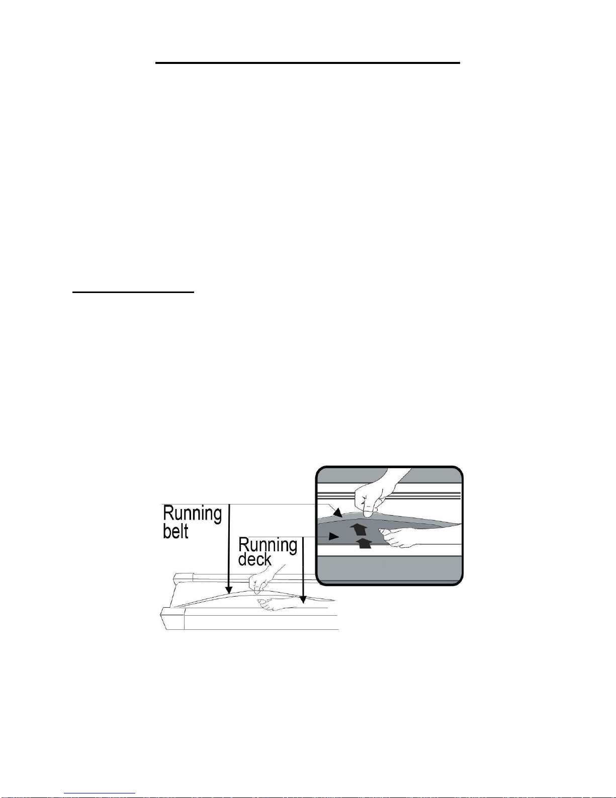
1. Raise the belt up on one side and apply lubricant to the running deck. Use a rag to
thoroughly wipe the lubricant over the running deck. Repeat this process for the other
side.
2. The moving parts should turn freely and quietly. Abnormality of moving parts will
affect the safety of the equipment. Inspect and tighten bolts regularly.
3. To better maintain the treadmill and prolong its lifespan, it is suggested that
maintenance be done on a regular basis.
4. A loose running belt will result in the runner sliding off during use, while too tight of a
running belt will decrease the motor performance and also create more friction between
the roller and running belts. The most suitable tightness for the belt is pulled out
50-75mm from the Running Board.
The following time table is recommended:
Light user (less than 3 hours/ week) every six months
Medium user (3-5 hours/ week) every three months
Heavy user (more than 5 hours/ week) every two months
12
Page 14

Place your hand at position
“H” and lift up on the Main
Frame (No. A) until the Air
Pressure Cylinder (No.
B03) “K” locks into the tube.
When the Air Pressure
Cylinder (No. B03)
successfully locks into the
tube, you will hear a clicking
sound.
Before lowering the Main
Frame (No. A), ensure that
the space directly underneath
it is clear of any objects.
Grasp the Main Frame (No.
A) at position “H” with one
hand. Next, using your foot,
firmly push against the Air
Pressure Cylinder (No. B03)
“K” and press down on the
Main Frame. Once the Main
Frame has been pushed
down, it will automatically
continue to steadily lower
itself until it reaches level
ground.
FOLDING INSTRUCTIONS
FOLDING:
UNFOLDING:
13
Page 15
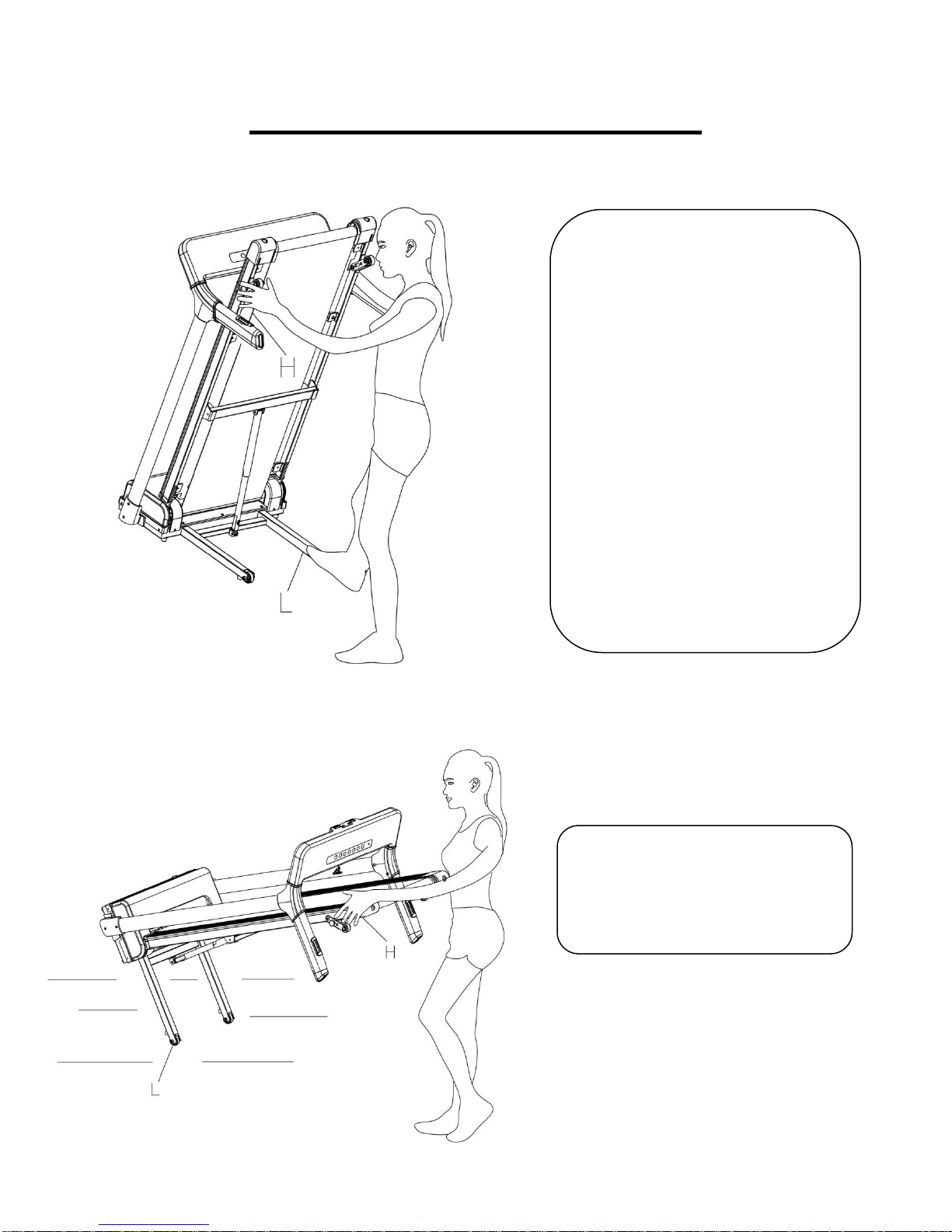
Before attempting to move the
treadmill, make sure that it has
been properly folded. Unplug
the power cord.
To tilt, start by placing one
hand at position “H” to support
the top end of the treadmill.
Next, place one foot at position
“L” to hold the bottom end of
the treadmill steady. With
your foot at “L”, slowly tilt the
top of the treadmill downward
towards the ground. Once the
Main Frame “H” reaches a low
enough point, the wheels of the
treadmill touch the ground.
To transport, hold the treadmill
from position “H” and tilt until
the wheels “L” are able to move
on the ground.
HOW TO MOVE THE MACHINE
14
Page 16
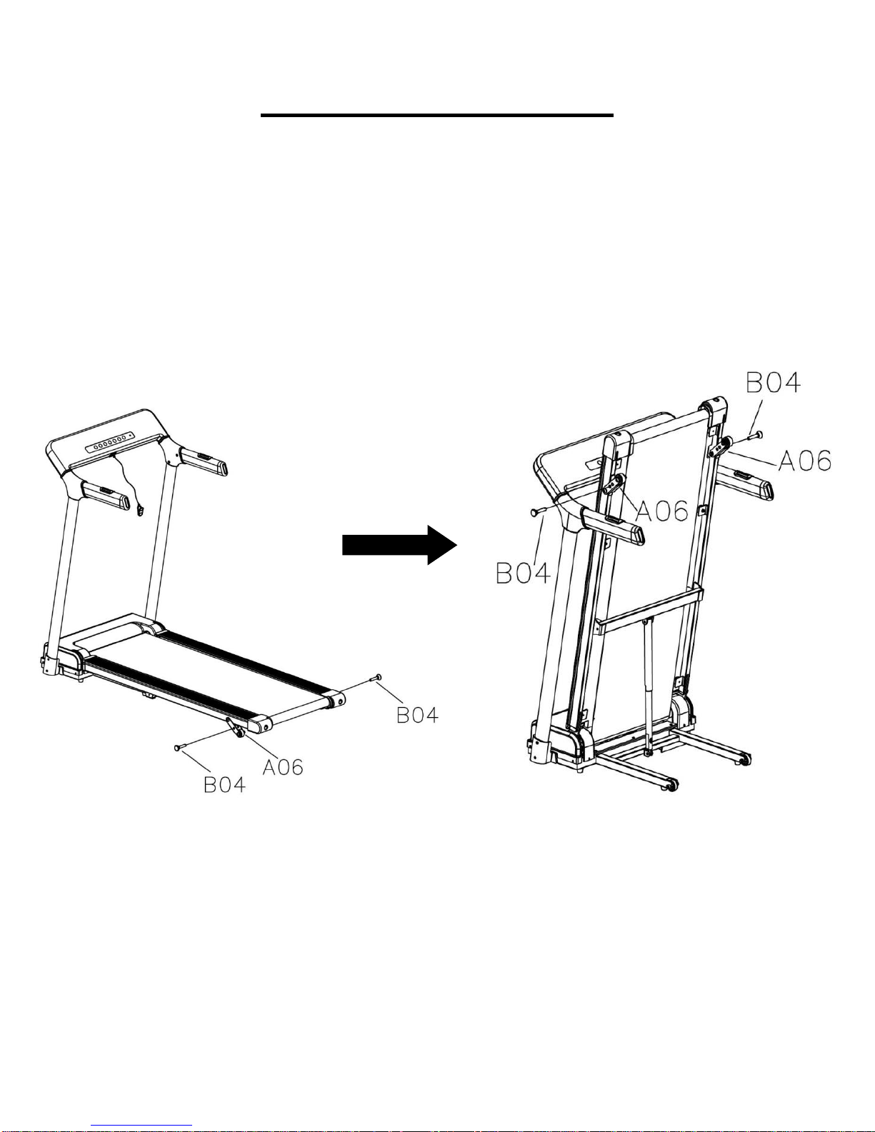
ADJUSTING THE INCLINE
ATTENTION: For your safety and convenience, always fold the treadmill (as
shown below) before attempting to adjust the incline.
There are two holes located on the Adjustable Foot Pad (No. A06). To adjust the level
of incline, remove the two Fixing Pins (No. B04) from the left and right side. Align the
holes of the Adjustable Foot Pad (No. A06) to the holes located on the Main Frame
(No. A). Once you’ve locate your desired incline level, reinsert the Fixing Pins (No. B04)
back through the holes.
15
Page 17
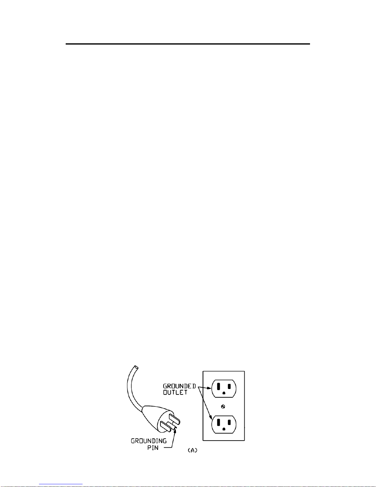
GROUNDING METHOD
IMPORTANT ELECTRICAL INFORMATION
WARNING: This treadmill requires a power source of 10 amps (100-120V) in
order to properly operate. For your safety, as well as the safety of others, please verify
that the power source is correct before plugging the equipment. Any power source above
or below this level could cause significant damage to the equipment and or user.
GROUNDING METHODS:
This product must be grounded. Grounding provides the least resistance for electrical
current and will reduce the risk of electric shock. The plug must be plugged into an
appropriate outlet that is properly installed and grounded in accordance with all local
codes and ordinances. Ensure that the product is connected to an outlet which contains
the same configuration as the plug. Do not use an adaptor for this product.
This product is for use on a nominal 100-120V circuit and has a grounding plug that
looks like the plug illustrated in sketch A. Make sure that the product is connected to an
outlet having the same configuration as the plug. No adapter should be used with this
product.
DANGER:
Improper connection of the equipment-grounding conductor can result in risk of electric
shock. Check with a certified electrician if you are in doubt as to whether the product is
properly grounded. Do not modify the plug provided with the product. If it will not fit the
outlet, have a proper outlet installed by an electrician.
WARNING!
1. NEVER use a ground fault circuit interrupt (GFCI) wall outlet with this treadmill. Route
the power cord away from any moving part of the treadmill including the elevation
mechanism and transport wheels.
2. NEVER operate the treadmill using a generator or UPS power supply.
3. NEVER remove any cover without first disconnecting AC power.
4. NEVER expose the treadmill to rain or moisture. This treadmill is not designed for use
outdoors, near pools or in any other high humidity environment.
16
Page 18
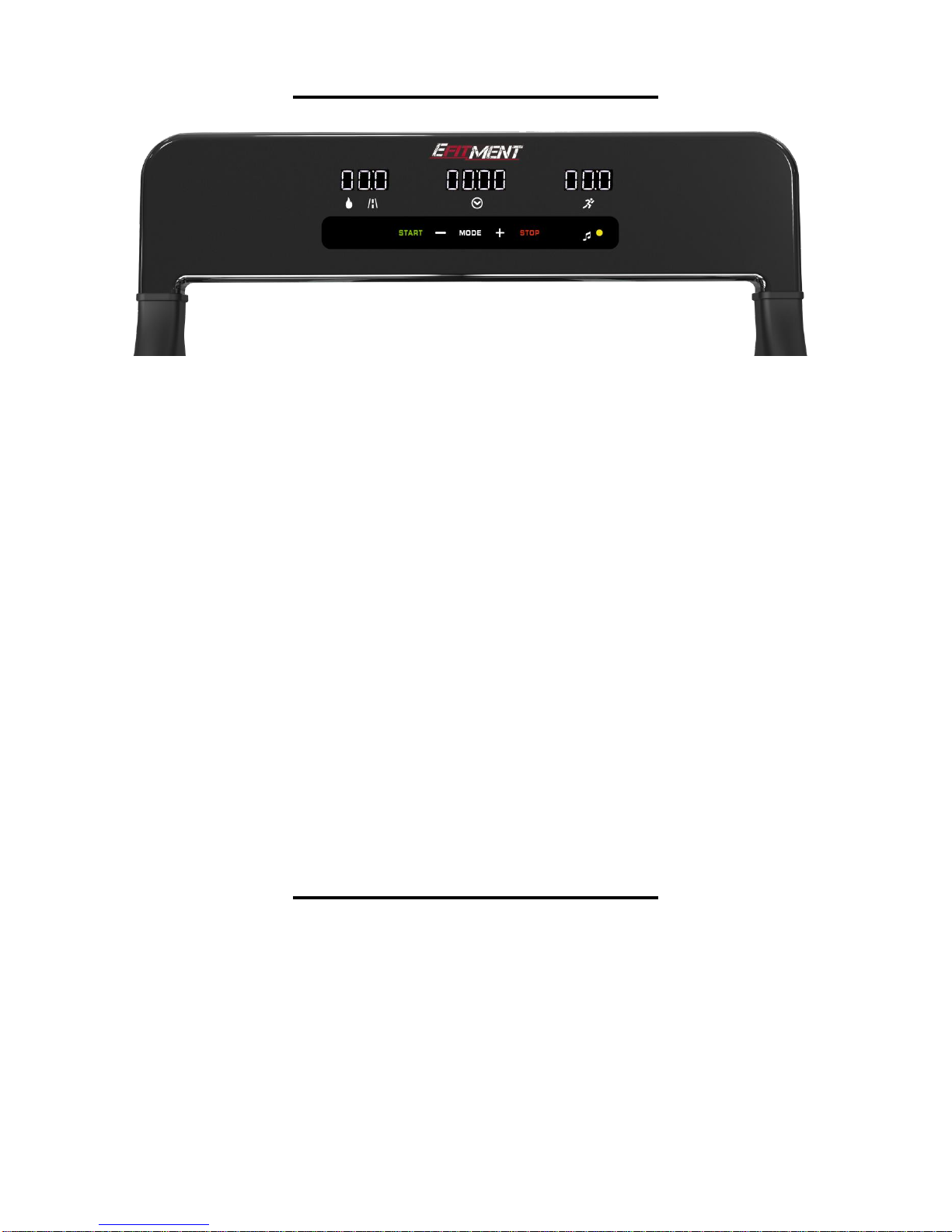
THE DISPLAY CONSOLE
QUICK START:
1. Insert the magnet end of the safety key into the computer console. Turn on the power
switch.
2. Press the START button, and the system will automatically display a 3 second
countdown. Once the countdown reaches zero, the running belt will start at the initial
default speed of 0.5 MPH.
3. To adjust the speed, you can use the SPEED +/- BUTTONS.
*NOTE: The maximum speed on this treadmill is 7.5 MPH
CONTROL FUNCTIONS:
1. Press the – Speed Button to reduce the running speed.
2. Press the + Speed Button to increase the running speed.
3 Pressing the STOP Button will PAUSE the running belt and current workout data.
Pressing the STOP button again will terminate current workout session completely.
4. Holding the Pulse Sensors located on the handles with both hands for 5 seconds will
calculate and display the runner’s heartbeats per minute (BPM) on the computer display
screen.
THE DISPLAY CONSOLE
WINDOW DISPLAY
1. SPEED/ PULSE: The speed range is 0.5-7.5 MPH. 0.5 MPH is the default running speed.
When the runner holds both hands on the pulse sensors (located on the handles), the
system will calculate the runner’s heart beat and display it in this window. The pulse range
is 50-200 beats/min (This data is just for reference, and cannot be used as the medical
data).
2. TIME: Displays the time elapsed (0:00-99:59 MINS). If the time reaches 99:59, the
machine will stop smoothly and display “END” then automatically reset to 0:00 after 5
seconds. When in Countdown Mode, it will count from the setting time to 0:00. When the
clock reaches 0:00, the machine will stop smoothly and display “End” then automatically
reset itself after 5 seconds.
17
Page 19
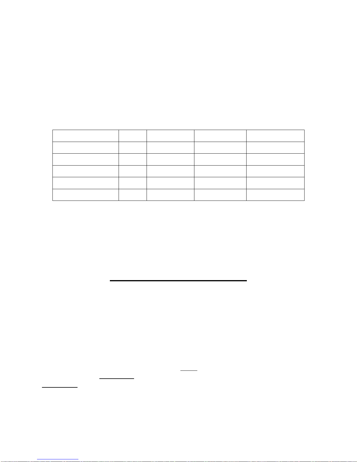
3. CALORIES/DISTANCE: Displays the amount of calories burned from 0 to 999 KCAL and
PROGRAMS
Initial
Default Value
Set Range
Display Range
TIME(MIN:SECOND)
0:00
15:00
5:00-99:00
0:00-99:59
SPEED(MPH)
0.5
0.5
0.5-7.5
0.5-7.5
DISTANCE(MILE)
0.00
1.00
0.50-99.9
0.00-99.9
PULSE(BPM)
P
N/A
N/A
50-200
CALORIE(KCAL)
0
50
10-999
0-999
the incline level from 0-15. When the count reaches 999, it will reset and start back from 0.
When in Countdown Mode, it will count down from the desired setting to 0. Once it reaches 0,
the machine will stop smoothly and display “End”, then automatically reset to the initial
setting after 5 seconds.
Displays the distance traveled (0.0-99.9 MILES). When the clock reaches 99.9, it will reset
to 0.00 and begin counting again from 0.0. When in Countdown Mode, it will count down
from the setting data to 0.00. When it reaches 0.00, the machine will stop smoothly and
display “End” and automatically reset to the initial setting after 5 seconds. When setting
PROGRAMS, the speed is programmed in intervals; PROGRAMS are from P1-P9.
THE DISPLAY CONSOLE
FUNCTION KEYS:
1. START: To start the machine, insert the magnet end of the safety key into the
computer console and then press the START button. This machine requires the Safety
Key in order to start. 0.5 MPH is the default start speed.
2. STOP: This button has functions of PAUSE and STOP. When in use, press this button
once to PAUSE your workout and the current workout data will still be shown. Press
STOP again to terminate your workout session complete and all data will be deleted and
reset to the initial setting.
3. MODE: When stopped, press this button to select a MODE. Pressing once will enter
“0.0”, the default operating mode. H1 is the TIME countdown mode starting from 15:00
MINS. H2 is the DISTANCE Countdown Mode starting from 1 MILE and H3 is the
CALORIES countdown mode which starts from 50 KCAL. P1-P2……P9 are preset
programs. When setting each mode and programs, you can press speed +/- to increase
or decrease from the set data. Press START to start the machine.
5. SPEED +/– BUTTONS: Press the +/- buttons to increase or decrease the speed in
increments of 0.1 MPH. Pressing and holding either of these buttons for a duration of
over ½ a second will increase or decrease the speed continually.
18
Page 20
PLAYING MUSIC
TIME INTERVAL= setting time/10
1 2 3 4 5 6 7 8 9
10
P1
SPEED
1.2
2.5
1.8
2.5
1.8
3.1
2.5
1.2
3.1
1.8
P2
SPEED
1.2
3.1
2.5
3.7
2.5
3.7
2.5
1.2
2.5
1.2
P3
SPEED
1.2
3.1
2.5
3.1
2.5
3.1
2.5
1.2
1.8
1.2
P4
SPEED
1.8
3.7
4.3
3.1 5 3.1
5.6
3.7
2.5
1.8
P5
SPEED
1.8
3.7
4.3
3.1 5 3.7
4.3
3.7
2.5
1.8
P6
SPEED
1.2
5
3.7
2.5
3.1
5.6
4.3
3.1
2.5
1.8
P7
SPEED
1.2
3.7
4.3
2.5
2.5
4.3
2.5
1.2
2.5
1.2
P8
SPEED
1.2
2.5
3.7 5 4.3 5 3.7
1.2
1.8
1.2
P9
SPEED
1.2
2.5
3.1
3.1
3.7
3.1
3.7
1.8
1.8
1.2
You can connect your mobile device to the treadmill to play music. You choose music
and adjust the volume of music using your device buttons. There are 2 ways to connect:
1. Connect your device using the MP3 wire (No.G05).
2. Connect your device using Bluetooth.
To connect using Bluetooth, make sure the MP3 wire (No.G05) is disconnected. If the
MP3 wire is connected, the Bluetooth will not function. When you turn on the treadmill, it
will say, “The Bluetooth device is ready to pair.” From your mobile device, select SYMK
from the list of available devices and connect. If the device is connected, treadmill will
say, “The Bluetooth device is connected successfully.”
If the mobile device receives a phone call while it is connected using Bluetooth, the
treadmill Bluetooth will automatically disconnect. When you want to resume playing
music on the treadmill, you will have to connect again.
LUBRICATION REMINDER
Your treadmill needs lubrication maintenance every 188 miles. The system will release a
beeping sound every 10 seconds and display an “OIL” icon on your LCD display to
remind you when it’s time. Please read the LUBRICATING THE TREADMILL on Page
12 to learn the proper steps to lubricating your machine. Apply the lubricating oil to the
middle of the running deck on both sides. After application, press and hold the STOP
button for 3 seconds to clear the reminder.
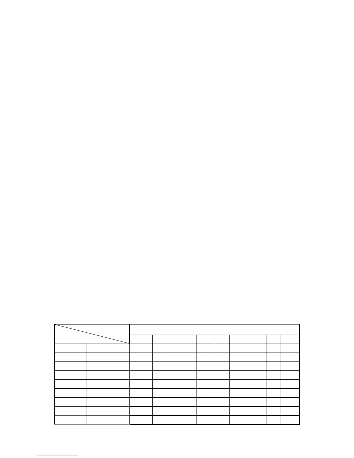
INTERVAL PROGRAMS (P1-P9):
Press the PROGRAM button to select an interval setting. Programs are displayed as
P1-P9. Select the desired program, and the console will display a countdown starting
from 10:00 MINS, press SPEED +/- BUTTONS if you wish to increase or decrease the
exercise time. Press the START button to start the interval program. The interval program
is divided into 10 sections. Each exercise time equals the setting time divided by 10.
When the speed enters the next interval, the treadmill will beep, and the speed will be
changed according to the set interval. Press SPEED +/- BUTTONS to change the
SPEED. After finishing one program, the system will beep and display END. The machine
will gradually come to a stop, then automatically reset to the initial setting after 5 seconds.
19
Page 21
THE DISPLAY CONSOLE
F-1
Sex
01 Male
02 Female
F-2
Age
10------99
F-3
Height
40----80INCHES
F-4
Weight
44-----330LBS
F-5
BMI
≤19
Underweight
BMI
=(20---25)
Normal Weight
BMI
=(26---29)
Overweight
BMI
≥30
Obesity
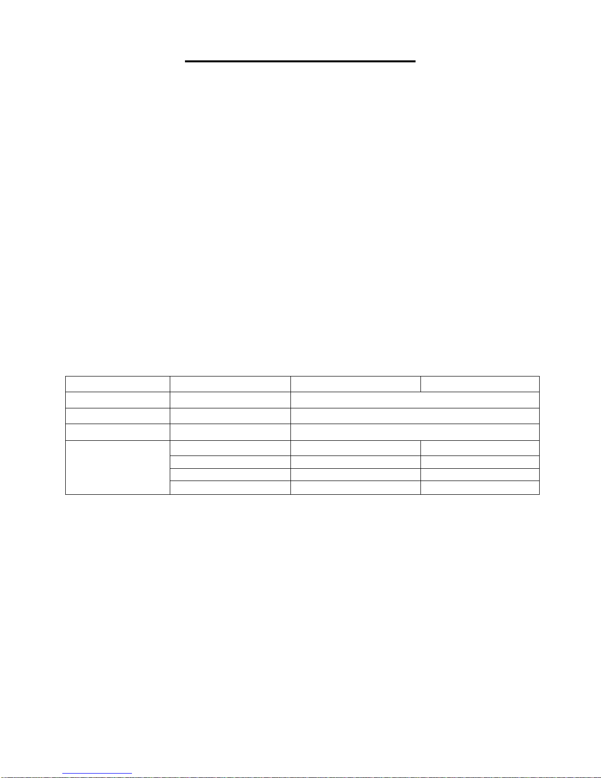
BODY MASS CALCULATION:
Press the PROGRAM button until the window displays FAT to access Body Mass
Calculation. Press MODE to enter F-1, F-2, F-3, F-4, F-5
F-1 SEX, F-2 AGE, F-3 HEIGHT, F-4 WEIGHT, F-5 is Body Mass Index
Press SPEED +/- BUTTONS to set F1-F4 (refer to the chart below). Once you have
finished setting F1-F4, press MODE. This will enter you into the set up for F-5(Body
Mass Index). To set F-5, grasp the Pulse Sensors located on the handles with both
hands and hold them for 3 seconds. The window will display your body mass index. The
Body Mass Index is used to test the relation between your height and weight. It is only for
reference not suitable for the medical use. The Body Mass Index is suitable for both male
and female.
NOTE: General Body Mass Index score is 20-25%
Underweight Below 19.0
Normal 19.0 – 25.0
Overweight 26.0 – 29.0
Obesity 30.0 – and above
BODY MASS INDEX (BMI) CHART:
20
Page 22

TREADMILL FUNCTIONS
SAFETY LOCK FUNCTION:
Removing the Safety Key (No. D10) from the computer console while the treadmill is
running will cause it to stop immediately. Once the treadmill reaches a full stop, the
window display of the computer will show “- - -“ and the buzzer will beep 3 times. To start
the treadmill again, insert the magnet end of the Safety Key (No. D10) into the computer
console and press the START button.
POWER SAVE FUNCTION:
When the treadmill has been idle for 10 minutes, it will enter Power Saving Mode. While
the treadmill is in this mode, the window display of the computer will be turned off. To turn
it back on, press any button.
POWER ON:
Flick the power switch to this symbol to turn on the treadmill.
POWER OFF:
Flick the power switch to this symbol to turn the treadmill off at anytime. This includes
during exercise.
SAFETY NOTE:
1. We recommend that you maintain a slow speed at the beginning of a session and hold
the handrails until you have become familiar with the treadmill.
2.Insert the magnet end of the Safety Key (No. D10) into the computer console and attach
the opposite end (containing the safety clip on it) to your clothing before starting your
workout. To end your workout, press the STOP button or remove the Safety Key
(No.D10) and the treadmill will stop immediately.
21
Page 23

EXERCISE INSTRUCTIONS
GETTING STARTED:
Before starting any exercise program, you should consult your physician to determine if
you have any medical or physical conditions that could put your health and safety at risk
or prevent you from using the equipment properly.
Be aware of your body’s signals. Incorrect or excessive exercise can damage your
health.
Stop exercising immediately if you experience any of the following symptoms: pain,
tightness in your chest, irregular heartbeat, shortness of breath, lightheadedness,
dizziness, or feelings of nausea.
Get to know your treadmill. Before attempting to use the treadmill take some time to
stand alongside and familiarize yourself with the controls.
1. Once you get on, you can stand with your feet on the side rails and stabilize
yourself by holding onto the handrails.
2. Next, attach the clip end of the Safety Key to your clothes and insert the magnetic
end of the key into the computer console.
3. Press the START button to start the machine.
4. The machine will start at the system default setting speed of 0.5 MPH. when you
feel comfortable, you may slowly increase this speed.
5. When you are finished with your exercise, press the STOP button to stop the
machine or you can remove the magnetic end of the Safety Key to stop the
machine.
22
Page 24

TROUBLESHOOTING
PROBLEM
POSSIBLE CAUSE
SUGGESTED ACTION
Treadmill will not start
Not plugged in
Plug cord into outlet
Safety Key not inserted
Insert Safety Key
Running belt not centered
Running belt tension not
correct on the left or right
sides of the running board
Tighten the adjustment bolts
on the left and right side of the
rear roller
Computer not working
Wires from the computer
and bottom control board
not properly connected.
Check wire connections
from the computer to the
control board.
Transformer is damaged
If the transformer is damaged,
contact customer service.
E01 or E13: Message
failure
Wires from the computer
and bottom control board
not properly connected.
Check wire connections from
the computer to the control
board. If the wire has been
punctured or damaged, you
will need to replace it. If the
problem is not rectified, you
may need to replace the
control board.
E02: Burst clash protection
Incoming voltage is lower
than 50% of the required
voltage.
Check that the incoming
power supply is the correct
voltage.
E03: No speed sensor
signal
Speed sensor signal
cannot be received by the
control board.
Check that the sensor wire is
properly connected. If
damaged, replace wire.
Check to see if the magnetic
sensor is damaged, replace if
necessary.
E05: Current overload
protection (Self Protecting
System)
The incoming voltage is
too low or too high. The
control board is damaged.
Restart the treadmill. Check
the incoming voltage to
ensure it’s correct. Check the
control board, replace if
damaged.
A moving part of the
treadmill is stuck and
therefore the motor is
unable to rotate properly.
Inspect moving parts of the
treadmill to ensure that they
are operating correctly. Check
the motor, listen for strange
noise and check for a burning
smell. Replace the motor if
necessary.
23
Page 25

E06: Motor Abnormality
The motor wire is not
connected or the motor is
damaged.
Check motor wires to see if
the motor is connected. If
the wire has been punctured
or damaged, you will need to
replace it. If the problem is
not rectified, you may need to
replace the motor
E08: Control Board
Abnormality
The control board is not
connected.
Check the upper and middle
wires to see if the control
board is connected. If the
wire has been punctured or
damaged, you will need to
replace it. If the problem is
not rectified, you may need to
replace the control board.
E10:Motor Abnormality
The motor is damaged or a
moving part of the treadmill
is stuck and therefore the
motor is unable to rotate
properly.
Inspect moving parts of the
treadmill to ensure that they
are operating correctly.
Replace the motor if
necessary.
NOTE: If you are unable to resolve an issue using the troubleshooting guide above,
please contact Customer Service at [email protected]
Version 1.1
24
 Loading...