

Page 1
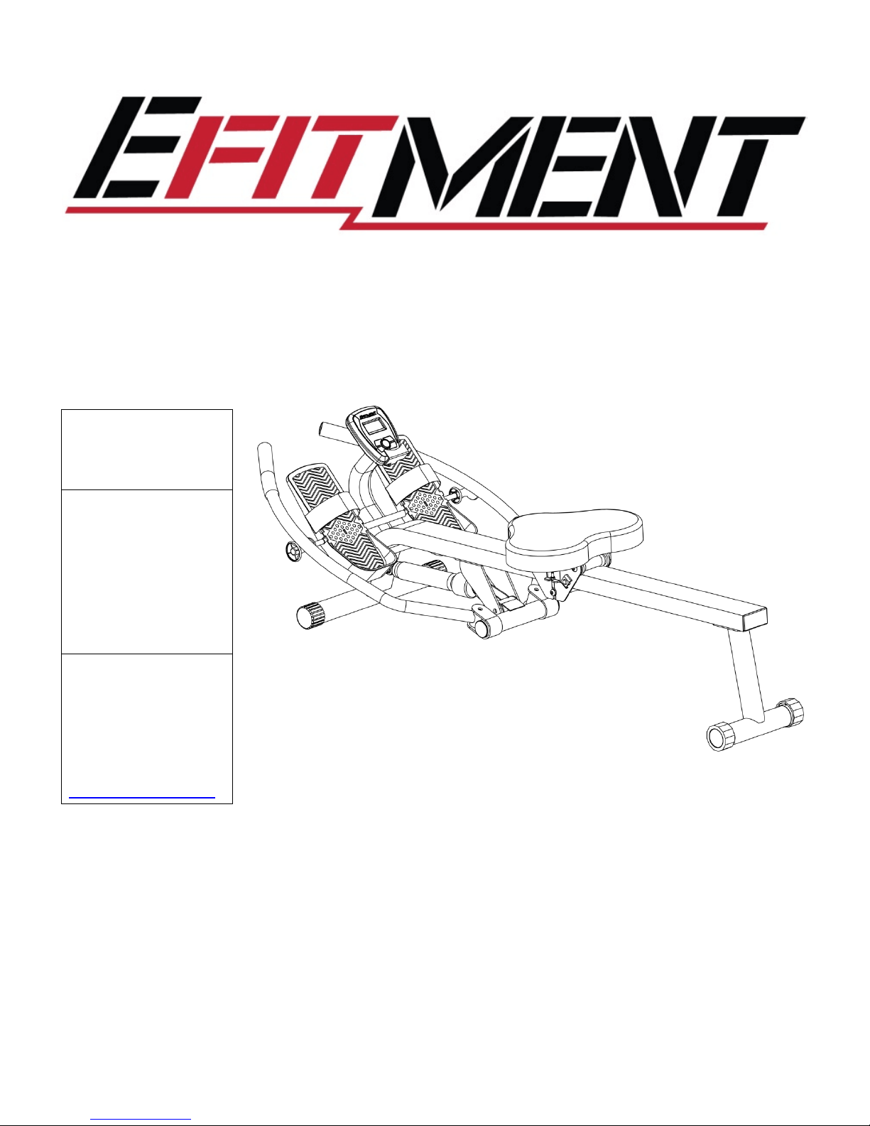
TOTAL MOTION ROWING MACHINE
MODEL NO.:
RW032
IMPORTANT! Read
all instructions
carefully before
using this product.
Save this manual for
future reference.
USER MANUAL
Page 2

2
IMPORTANT SAFETY INSTRUCTIONS
At Efitment your safety is our top priority and to make sure both you and the unit remain in perfect working
order, we encourage you to read all the instructions before assembling and using your new Efitment machine.
Do not skip, substitute or modify any steps or procedures herein, as doing so could result in personal injury
and will void your warranty.
1. Before starting any exercise program you
should consult your physician to determine if
you have any medical or physical conditions
that could put your health and safety at risk or
prevent you from using the equipment
properly. Your physician’s advice is essential if
you are taking any medication that may affect
your heart rate, blood pressure, or cholesterol
level.
2. Be aware of your body’s signals. Incorrect or
excessive exercise can damage your health.
Stop exercising if you experience any of the
following symptoms: pain, tightness in your
chest, irregular heartbeat, shortness of breath,
lightheadedness, dizziness, or feelings of
nausea. If you experience any of these
conditions, you should consult your physician
before continuing with your exercise program.
3. This equipment is intended for adult use only.
Keep children and pets away from the
machine. DO NOT leave children unattended
in the same room with the equipment.
4. Use the equipment on a solid, flat level
surface with a protective cover for your floor
or carpet. To ensure safety, the equipment
should have at least 2 feet of free space all
around it.
5. Check if you have all the components and tools
listed. Please note that some components are
pre-assembled to help make the assembly
process quick and easy.
6. Always use the equipment as intended. If you
find any defective components while
assembling or checking the equipment, or if you
hear any unusual noises coming from the
equipment during exercise, discontinue use
immediately and do not use until the problem
has been rectified.
7. Always wear appropriate workout clothing
when exercising. Do not wear clothing that can
get tangled in the equipment.
8. Keep hands and other objects away from all
moving parts.
9. The maximum user’s weight is 350 lbs/155 kgs.
10. Be careful when lifting and moving the
equipment. Always use proper lifting technique
and seek assistance if necessary.
11. Your equipment is intended for use in cool, dry
conditions. You should avoid storage in extreme
cold, hot, or damp areas as this may lead to
corrosion and other related problems.
12. This equipment is designed and intended for
indoor use only, not for commercial use.
SAVE THESE INSTRUCTIONS
Page 3
3
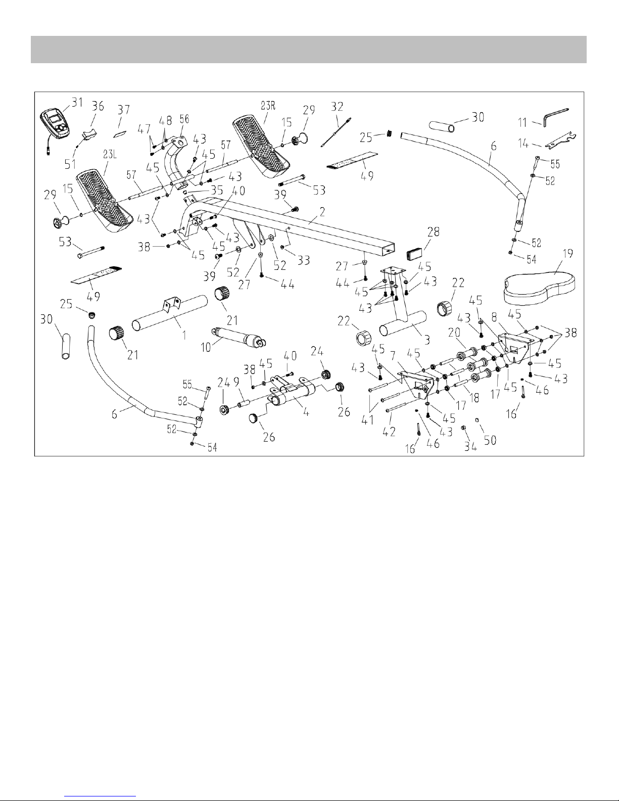
EXPLODED DRAWING
Page 4
4
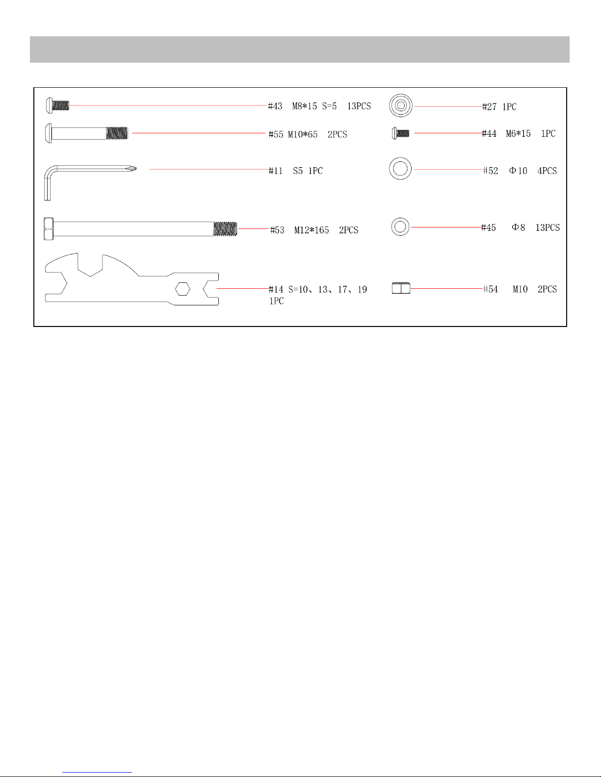
HARDWARE PACKAGE
Page 5
5
No.
Description
Qty.
No.
Description
Qty.
1
Front Stabilizer
1
30
Foam Grip L 200
2
2
Main Frame
1
31
Meter With E
1
3
Rear Support
1
32
Trunk Wire F with F
1
4
Rotating Armrest
1
33
Sensor
1
5
Refer to No.56
34
Induction Magnet Seat
1
6
Handlebar
2
35
Induction Wire Clip
1
7
Left Seat Supporting Board
1
36
Tablet Bracket
1
8
Right Seat Supporting Board
1
37
EVA Pad
1
9
Inner Sleeve Shaft
1
38
Nut M8
5
10
Hydraulic Cylinder Φ42*300
1
39
Screw M10*15 S=6
2
11
Allen Wrench S=5
1
40
Screw M8*40 20 S=5
2
12
Refer to No.55
41
Bolt M8*115 20 S=5
2
13
Refer to No.57
42
Bolt M8*120 20 S=5
1
14
Spanner S=10,13,17,19
1
43
Screw M8*15 S=5
13
15
Cir Clip Φ12
2
44
Screw M6*15
2
16
Adjusting Screw M6*45
2
45
Washer Φ8
24
17
Bearing 608Z
6
46
Nut M6
2
18
Spacer Tube Φ12*Φ8.2*78
3
47
Screw M5*12
2
19
Seat 1 48
Washer Φ5
2
20
Wheel
3
49
Pedal Strap
2
21
Front End Cap Φ50
2
50
Induction Magnet Φ15*3
1
22
Rear Adjustable End Cap Φ50
2
51
Screw ST
1
23L/R
Pedal
2
52
Washer Φ10
6
24
Plastic Axle Sleeve Φ42*Φ20*19
2
53
Screw M12*165
2
25
End Cap Φ28*2.0
2
54
Nut M10
2
26
End Cap Φ42*2.0
2
55
Bolt M10*65
2
27
Limit Mat
2
56
Meter Support
1
28
End Cap
1
57
Foot Rest Bolt Φ12*250
2
29
Armrest Limit Stopper
2
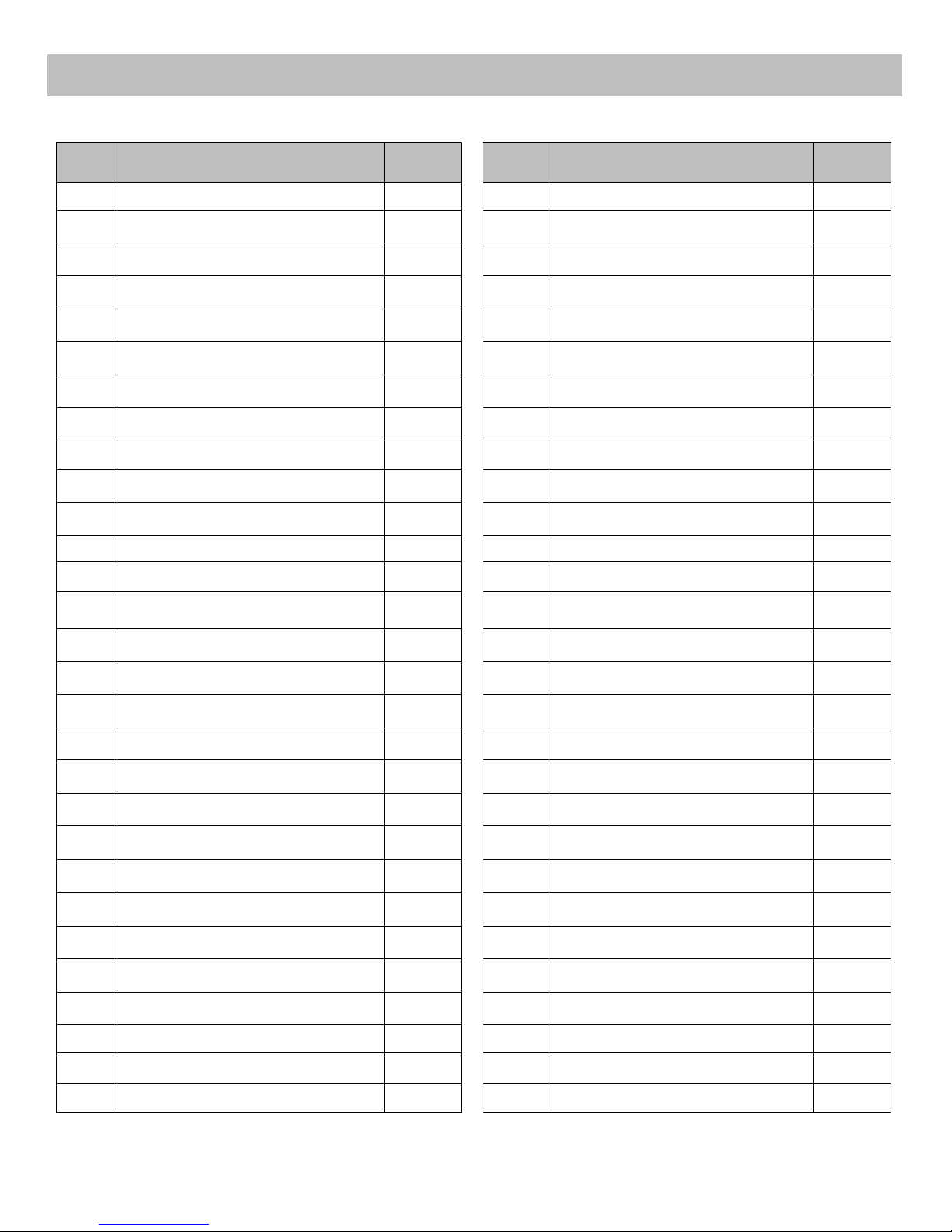
PARTS LIST
Page 6
6
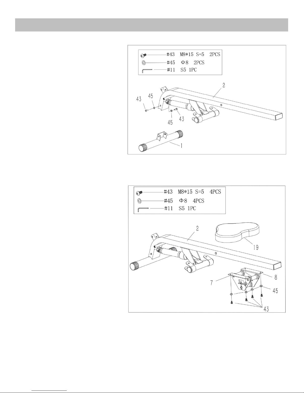
ASSEMBLY INSTRUCTIONS
STEP 1:
Attach the Front Stabilizer (No.1) to
the Main Frame (No.2) using 2 Screws
(No.43) and 2 Washers (No.45).
Tighten and secure with an Allen
Wrench (No.11).
STEP 2:
Attach the Seat (No.19) to the Seat
Supporting Boards (No.7 & 8) using 4
Screws (No.43) and 4 Washers (No.45).
Tighten and secure with an Allen
Wrench (No.11). Then Insert the Seat
(No.19) into the Main Frame (No.2).
Note: Please attach Seat Supporting
Boards (No. 7 & 8) in the direction of
the arrow labels to prevent installing
incorrectly.
Page 7
7
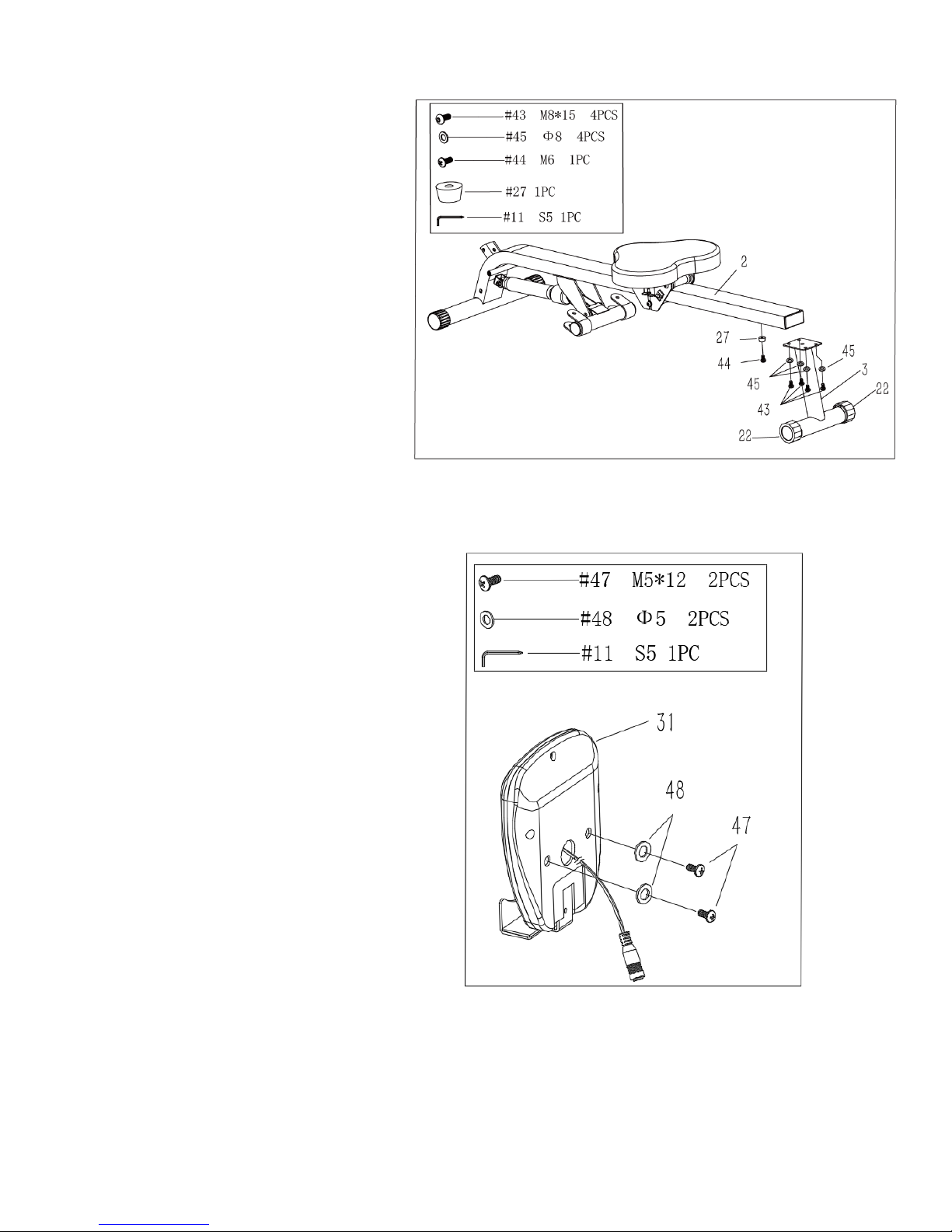
STEP 3:
Attach the Limit Mat (No.27) under the
Main Frame (No.2) using Screw (No.44),
then tighten with an Allen Wrench
(No.11).
Attach the Rear Support (No.3) onto the
Main Frame (No.2) using 4 Screws
(No.43) and 4 Washers (No.45). Tighten
and secure with an Allen Wrench
(No.11).
Note: To prevent tipping, rocking and
swaying on uneven surface, simply turn
Rear Adjustable End Cap (No.22).
STEP 4:
Remove the pre-assembled 2 Screws
(No.47) and 2 Washers (No.48) from the
Meter (No.31) with an Allen Wrench
(No.11).
Page 8
8
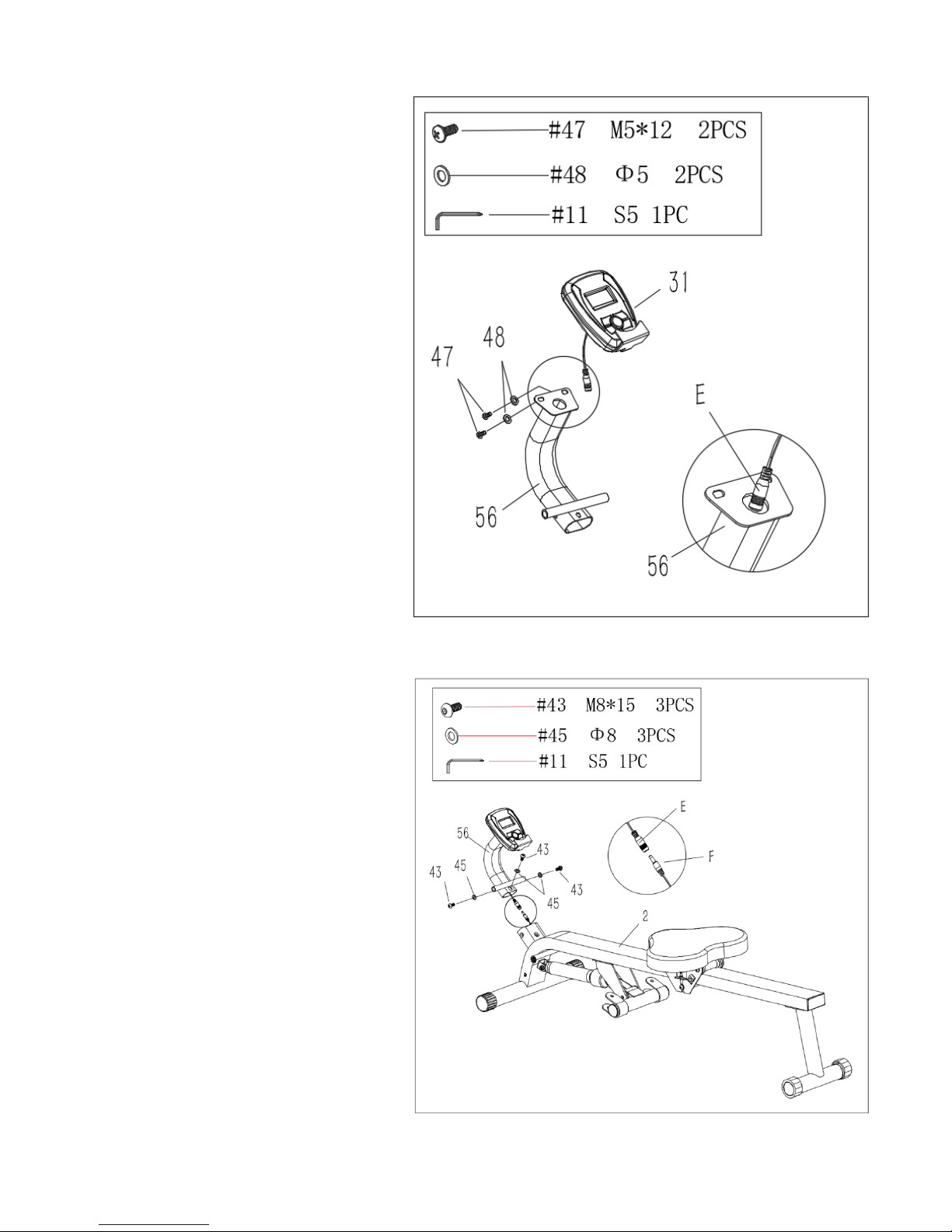
STEP 5:
Insert part E into the Meter Support
(No.56). Then attach the Meter (No.31)
onto the Meter Support (No.56) using
2 Screws (No.47) and 2 Washers
(No.48) that were removed, then
tighten with an Allen Wrench (No.11).
STEP 6:
Connect part E with part F. Attach the
Meter Support (No.56) onto the Main
Frame (No.2) using 3 Screws (No.43)
and 3 Washers (No.45). Tighten and
secure with an Allen Wrench (No.11).
Page 9
9
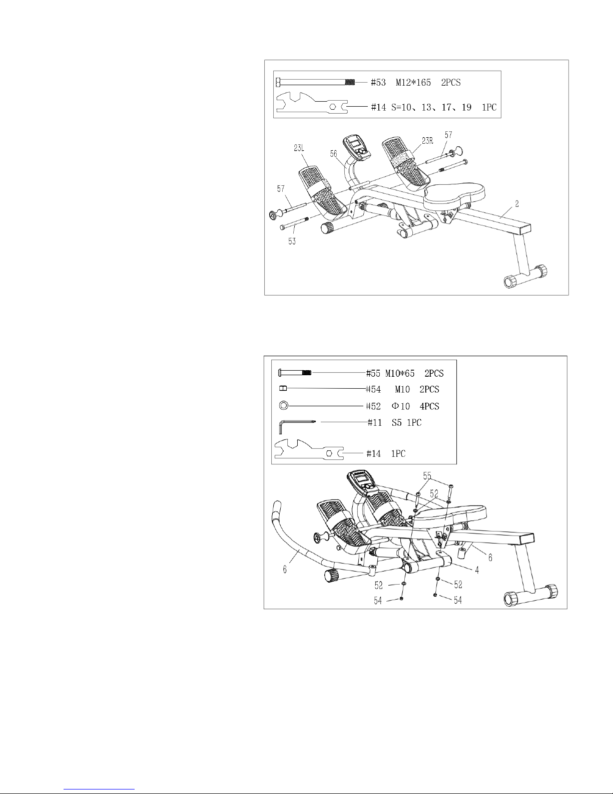
STEP 7:
Affix 2 Screws (No.53) into the Main
Frame (No.2) with a Spanner (No. 14).
Then insert the 2 Foot Rest Bolts
(No.57) through the Pedals (No.23) and
into the Meter Support (No.56).
NOTE: The Pedals (No.23) should rest
on the Bolts (No.53).
STEP 8:
Attach the 2 Handlebars (No.6) into the
Rotating Armrest (No.4) using 2 Bolts
(No.55), 4 Washers (No.52) and 2 Nuts
(No.54). Tighten and secure with an
Allen Wrench (No.11)and a Spanner
(No.14).
The assembly is complete!
Page 10
10
ADJUSTING THE RESISTANCE
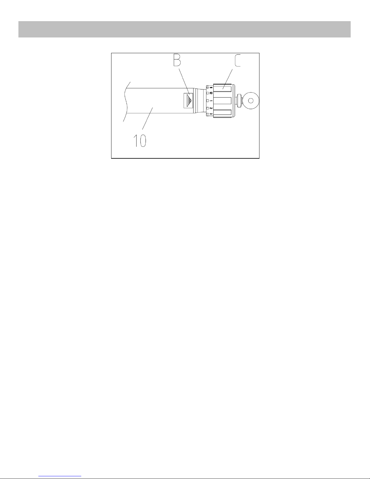
To adjust the tension level, turn the Adjustment Knob (C) on the Hydraulic Cylinder
(No.10) to the desired level. The tension levels range from Level 1 to Level 12, with
Level 1 being the lowest resistance. The number pointing to the Adjustment Knob (C)
by the Arrow (B) is the resistance value of the current Hydraulic Cylinder (No.10).
NOTE: Please do not adjust the resistance of the Hydraulic Cylinder (No.10) during
operation to avoid injury and damage to the machine.
WARNING:
The Hydraulic Cylinder (No.10) on this rower is designed to be used up to 20 minutes
per exercise session. Allow at least 20 minutes in between sessions for the Hydraulic
Cylinder (No.10) to properly cool down.
Caution: The Hydraulic Cylinder (No.10) can generate excessive heat after long
period of use, making it unsafe to touch. Allow the Hydraulic Cylinder (No.10) to cool
before moving the rower.
Page 11
11
ADJUSTING THE PEDAL
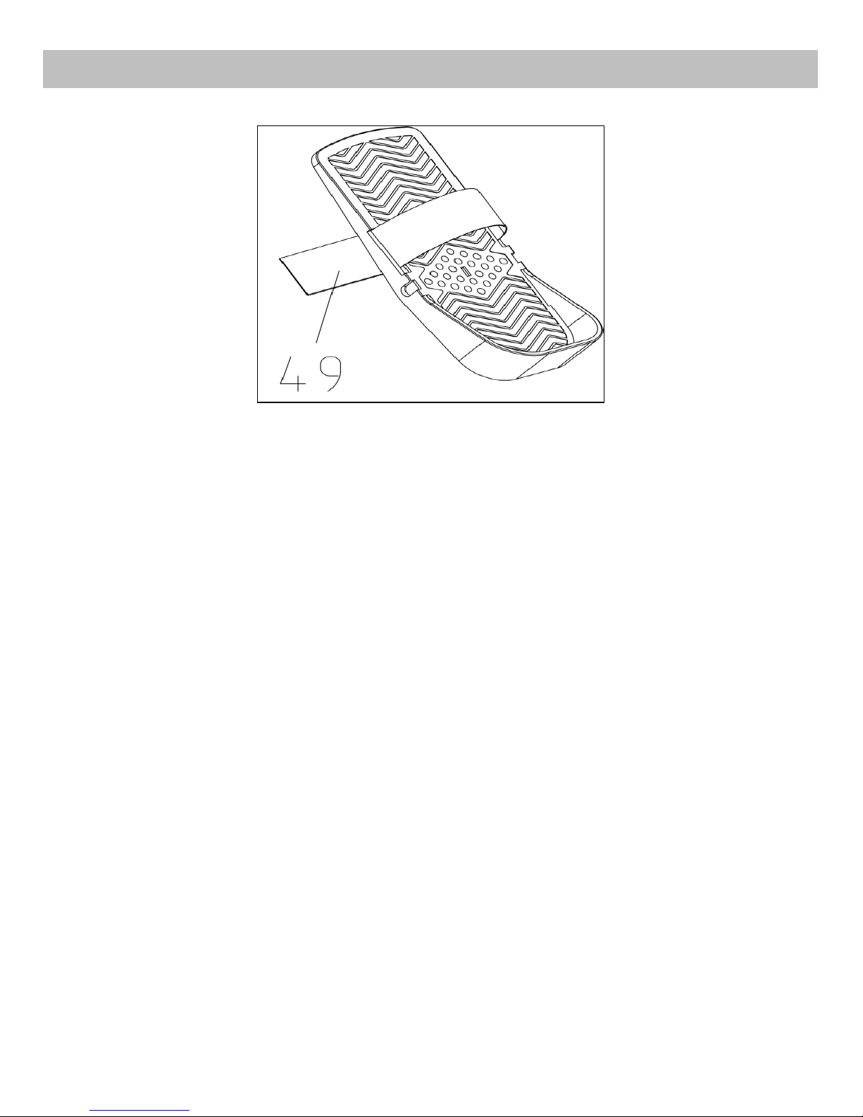
The Pedal Strap (No.49) is adjustable and can be personalized to fit the user’s
foot size.
To adjust the Pedal Strap (No.49), remove the velcro end of the strap from the
mesh side by pulling it upward then to the left.
Once removed, you may increase the opening of the Pedal Strap (No.49) by
pulling the mesh end up and to the right.
To tighten, pull the velcro end of the Pedal Strap (No.49) upward then to the right
and down to secure it to the mesh side of the strap.
Page 12

12
SPECIFICATIONS
TIME-----------------------------------------------------------------------------------------0:00-99:59 MINUTES
COUNT (CNT)------------------------------------------------------------------------------0-9999 TIMES
CALORIES (CAL)---------------------------------------------------------------------------0-999.9 CAL
TOTAL COUNT (TC)-----------------------------------------------------------------------0-9999 TIMES
RPM (C/M)---------------------------------------------------------------------------------0-9999 COUNT/MIN
KEY FUNCTION
MODE: This key lets you to select and lock on to a particular function you want.
CLEAR: Pressing and hold the MODE key with 3 seconds to reset the value to zero. But total count can only be
reset by changing battery.
OPERATION PROCEDURES
1. AUTO ON / OFF:
•The system turns on when the MODE key is depressed or when the system sensed a signal input from the
speed sensor.
•The system turns off automatically when the speed sensor has no signal input or no key are pressed for
approximately 4 minutes.
2. FUNCTION:
•SCAN: Automatically scan through all the functions played on the bottom of the meter.
•TIME: The total working time will be shown when starting exercise.
•CAL (CALORIES): The Computer will display total calories burns when starting to exercise.
•RPM(C/M): Counts each strokes within a minute.
•COUNT: Counts the number of rowing strokes from your current workout.
•TC (TOTAL COUNT): Counts the total amount of strokes from the first use.
•SELECT
You can operate the MODE key to select and lock on function in second rank of LCD screen for following
sequence:
TIME→ COUNT→ CALORIES →TOTAL COUNT→ RPM→SCAN
BATTERY:
This monitor uses 2pcs “AAA” batteries. You can replace the battery through the back of the unit. If there is a
problem with the display, try changing the batteries first. Do not mix old and new battery. Do not mix battery
types. Dispose old battery according to your regional guidelines.
EXERCISE COMPUTER
V 4
 Loading...