

Page 1
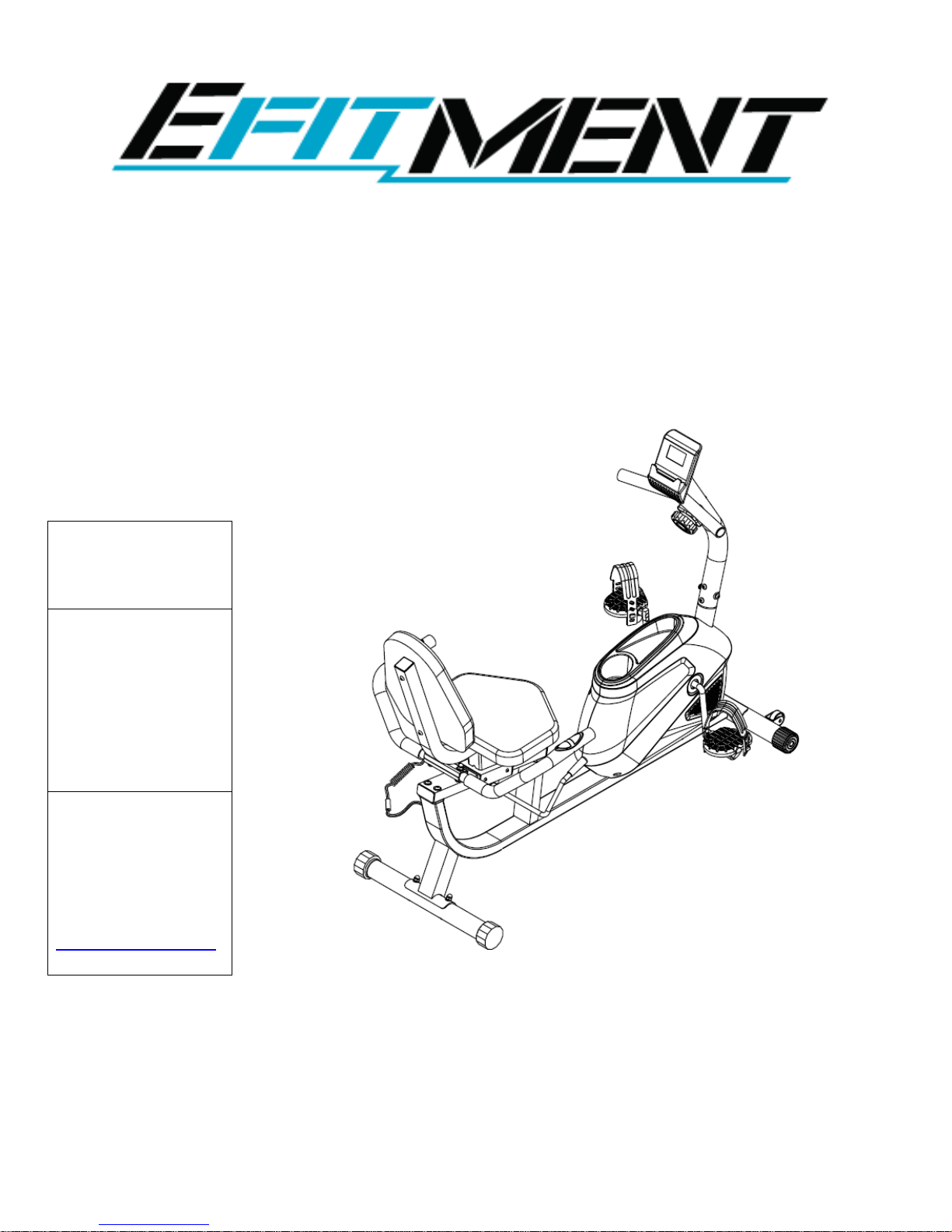
EFITMENT Magnetic Recumbent
Bike w/ Pulse Monitor
MODEL NO.:
RB034
IMPORTANT! Read
all instructions
carefully before
using this product.
Save this manual for
future reference.
USER MANUAL
Page 2
2
IMPORTANT SAFETY INSTRUCTIONS
At Efitment your safety is our top priority and to make sure both you and the unit remain in perfect working
order, we encourage you to read all the instructions before assembling and using your new Efitment machine.
Do not skip, substitute or modify any steps or procedures herein, as doing so could result in personal injury
and will void your warranty.
1. Before starting any exercise program you
should consult your physician to determine if
you have any medical or physical conditions
that could put your health and safety at risk or
prevent you from using the equipment
properly. Your physician’s advice is essential if
you are taking any medication that may affect
your heart rate, blood pressure, or cholesterol
level.
2. Be aware of your body’s signals. Incorrect or
excessive exercise can damage your health.
Stop exercising if you experience any of the
following symptoms: pain, tightness in your
chest, irregular heartbeat, shortness of breath,
lightheadedness, dizziness, or feelings of
nausea. If you experience any of these
conditions, you should consult your physician
before continuing with your exercise program.
3. This equipment is intended for adult use only.
Keep children and pets away from the
machine. DO NOT leave children unattended
in the same room with the equipment.
4. Use the equipment on a solid, flat level
surface with a protective cover for your floor
or carpet. To ensure safety, the equipment
should have at least 2 feet of free space all
around it.
5. Check if you have all the components and tools
listed. Please note that some components are
pre-assembled to help make the assembly
process quick and easy.
6. Always use the equipment as intended. If you
find any defective components while
assembling or checking the equipment, or if you
hear any unusual noises coming from the
equipment during exercise, discontinue use
immediately and do not use until the problem
has been rectified.
7. Always wear appropriate workout clothing
when exercising. Do not wear clothing that can
get tangled in the equipment.
8. Keep hands and other objects away from all
moving parts.
9. The maximum user’s weight is 300 lbs / 135kgs.
10. Be careful when lifting and moving the
equipment. Always use proper lifting technique
and seek assistance if necessary.
11. Your equipment is intended for use in cool, dry
conditions. You should avoid storage in extreme
cold, hot, or damp areas as this may lead to
corrosion and other related problems.
12. This equipment is designed and intended for
indoor use only, not for commercial use.
SAVE THESE INSTRUCTIONS
WARNING: This product can expose you to one or more chemicals known to the State of California to
cause cancer and birth defects or reproduction harm. For more information go to
www.P65Warnings.ca.gov.
Page 3
3
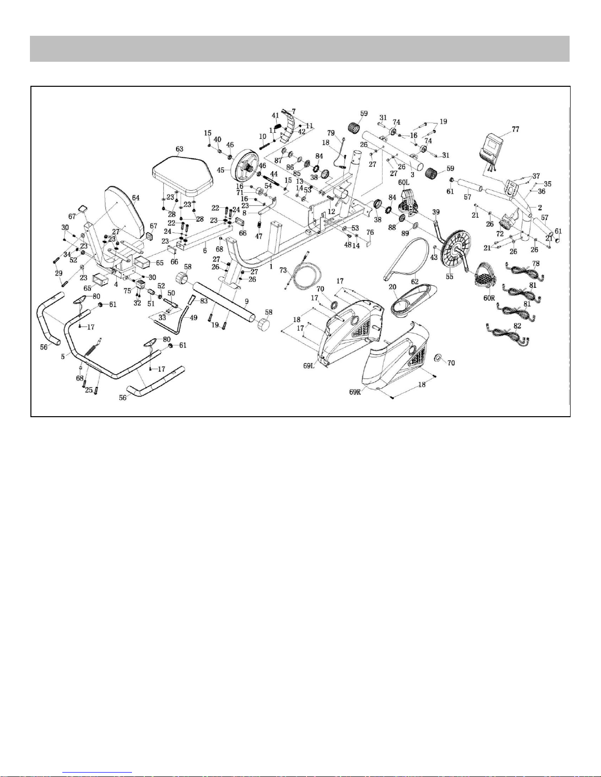
EXPLODED DRAWING
Page 4
4
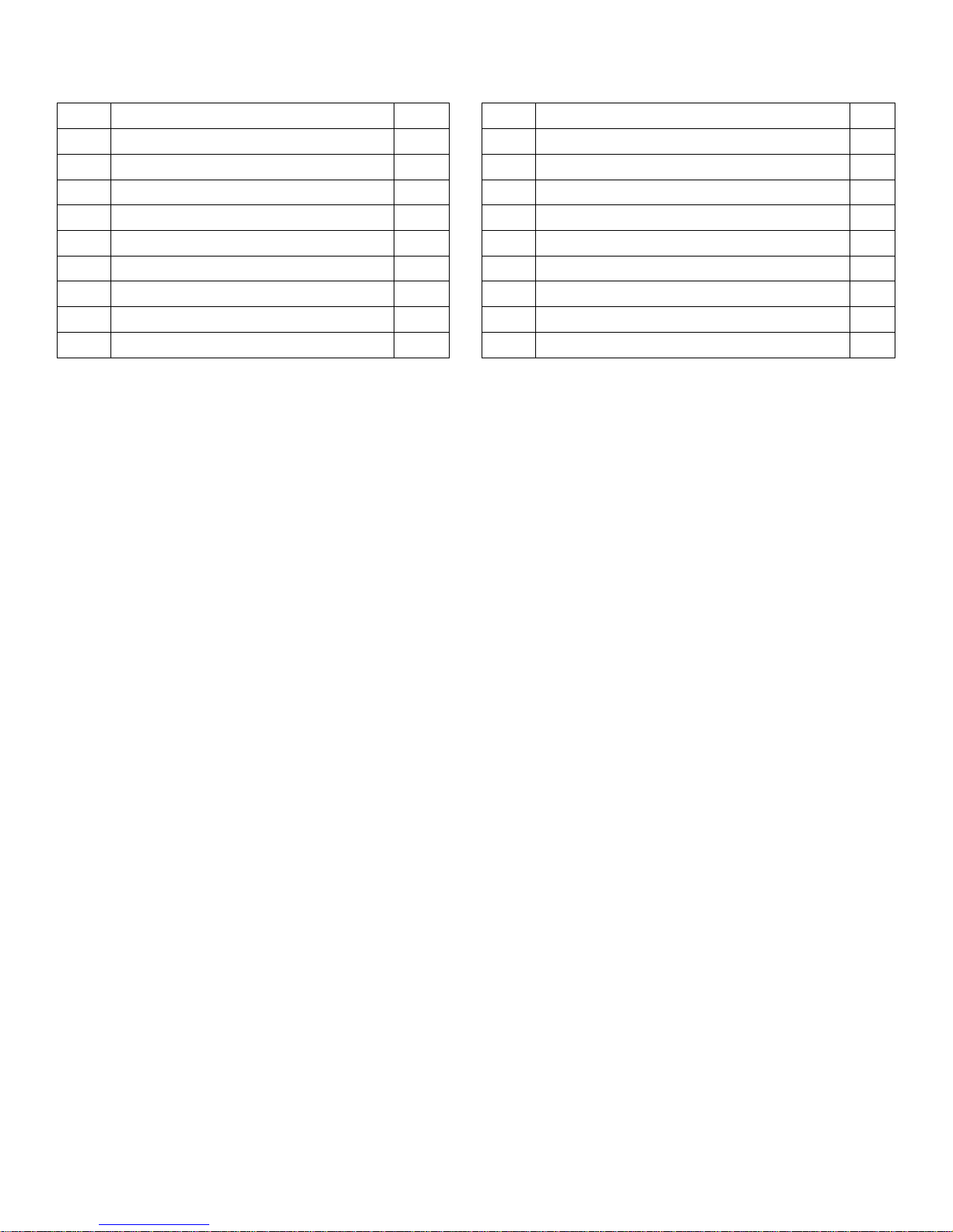
No.
Description
Qty.
No.
Description
Qty.
1
Main Frame
1 37
Bolt M5*10 Full Teeth
2
2
Front Post
1 38
Bearing Housing Ø56*15.5
2 3 Front Stabilizer
1 39
Crank 140*220 1/2
1
4
Cushion Frame
1 40
Flywheel Spacer 16*10.2*17
1 5 Handlebar
1 41
Tension Spring 18*48
1
6
Seat Adjusting Tube
1 42
Black Magnet 40*25*10
9 7 Magnetic Board
1 43
Round Magnet 15*6
1
8
Idler Link
1 44
Inertia Wheel 10*125*M10*1*17
1 9 Rear Stabilizer
1 45
External Magnetic Flywheel 200*72.5/3kg
1
10
Hex Tap Bolt M6*70
1 46
Bearing 6000Z
2
11
Hex Nut M6
2 47
Tension Spring 18*48
1
12
Hex Tap Bolt M6*70
1 48
Tap Bolt 9.8*4*M8*15
1
13
Plastic Nut M8 S13
1 49
Brake Handle 12*380
1
14
Hex Thin Nut M10*1*H5
2 50
Eccentric Shaft 12*105
1
15
Taper Thin Nut M10*1*H4
2 51
Eccentric Wheel 20*38
1
16
Plastic Nut M8 S13
4 52
Bushing Set 23*12.2*11
2
17
Screw ST4.2*20
8 53
Lock Washer 30*2
2
18
Screw ST4.2*20
5 54
Idler Spacer 16*10.2*10
1
19
Carriage Bolt M8*60,8,20
4 55
Pulley 240/J6
1
20
Upper Cover
1 56
Foam Grip 3*33*450
2
21
Bolt M8*20 Full Teeth S5
4 57
Foam Grip 3*33*160
2
22
Bolt M8*45,20,S5
4 58
End Cap
2
23
Flat Washer Ø8* Ø16*1.5
13 59
End Cap
2
24
Spring Washer Ø8
4 60L/R
Pedal
1
25
Carriage Bolt M8*42
2 61
Round End Cap 25*1.5 Tube
4
26
Arc Washer Ø8* Ø16*1.5
8 62
Leather Belt 370 PJ6
1
27
Cap Nut M8
6 63
Seat Cushion 360*280*40
1
28
Bolt M8*16,S5
4 64
Backrest Cushion 380*290*40
1
29
Bolt M8*50,20,S5
2 65
Sleeve 80*40*1.5 Tube
2
30
Screw M5*8
4 66
End Cap
2
31
Screw M8*38, 15-S5
2 67
End Cap
2
32
Screw M5*15
2 68
Plug
2
33
Screw M6*15 S5
2 69L/R
Belt Cover
1
34
Lock Washer for Shaft D12
1 70
Crank Plug
2
35
Bolt M5*45 Full Teeth
1 71
Arc Idler Ø 43.5*25 included a 6000 Bearing
1
36
Arc Washer 20*6*1
1 72
Tension Knob 280mm Wire
1
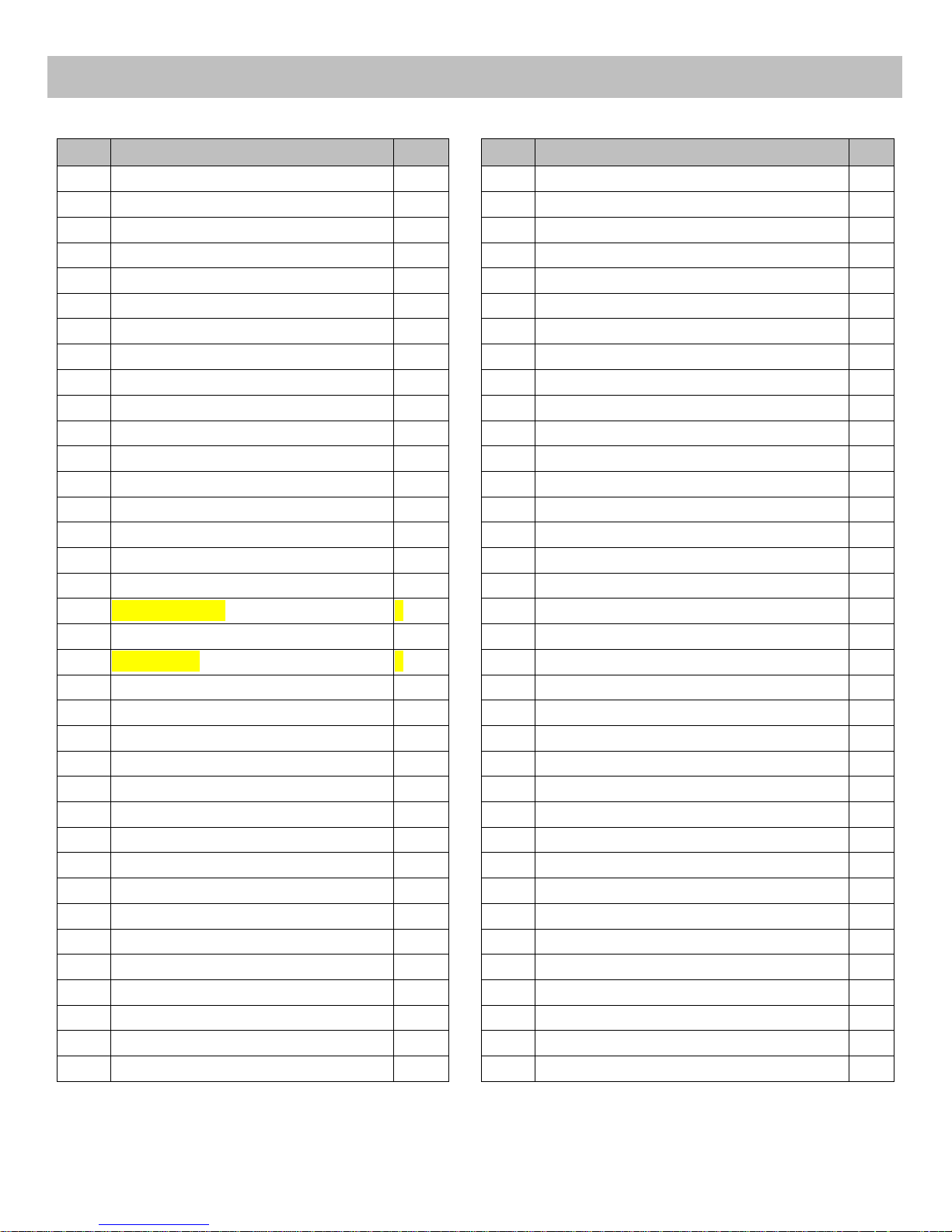
PARTS LIST
Page 5
5
73
Tension Wire 760mm
1
83
Brake Handset 24*77*Hole 12
1
74
Transportation Wheel 41*8.5*20
2
84
Bearing Ø46*8
2
75
Brake Block 40*38*32
1
85
Two Groove Nut Ø46*12 Teeth on Left
1
76
EV Pad 40*20*3
1
86
Locking Washer Ø46*2
1
77
Computer
1
87
Hex Nut 32*32*4
2
78
Trunk Line 1 600mm
1
88
Three Slot Nut Ø46*12
1
79
Needle Sensor Line 500mm with Seat
1
89
Washer Ø40.5*3
1
80
Hand Pulse Sensor 700mm
2 90
Spanner S=13 14 15 17 Ø5
1
81
Hand Pulse Wire 1 600mm
2 91
Allen Wrench S5
1
82
Hand Pulse Wire 2 1600mm
1
Page 6
6
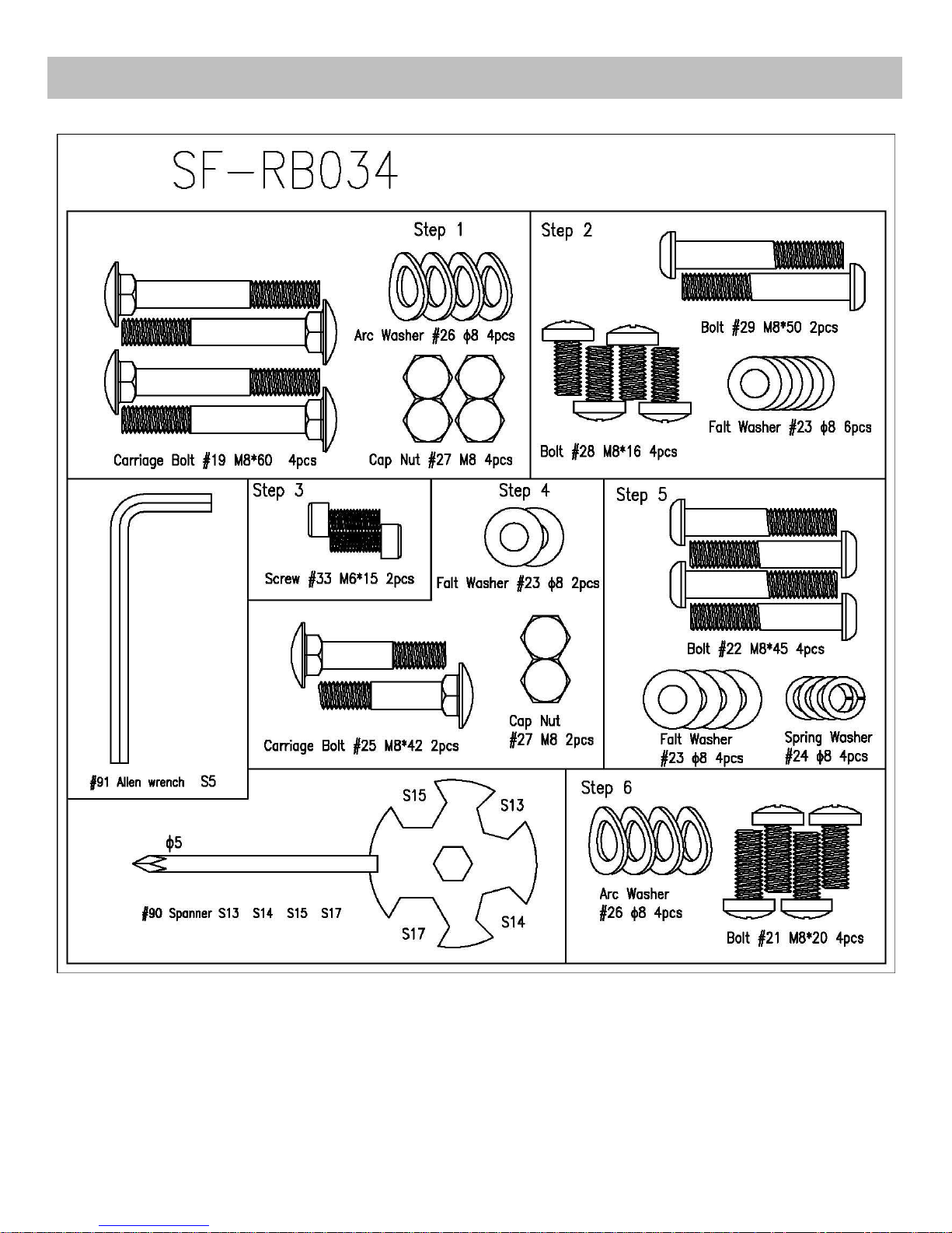
HARDWARE PACKAGE
Page 7
7
ASSEMBLY INSTRUCTIONS
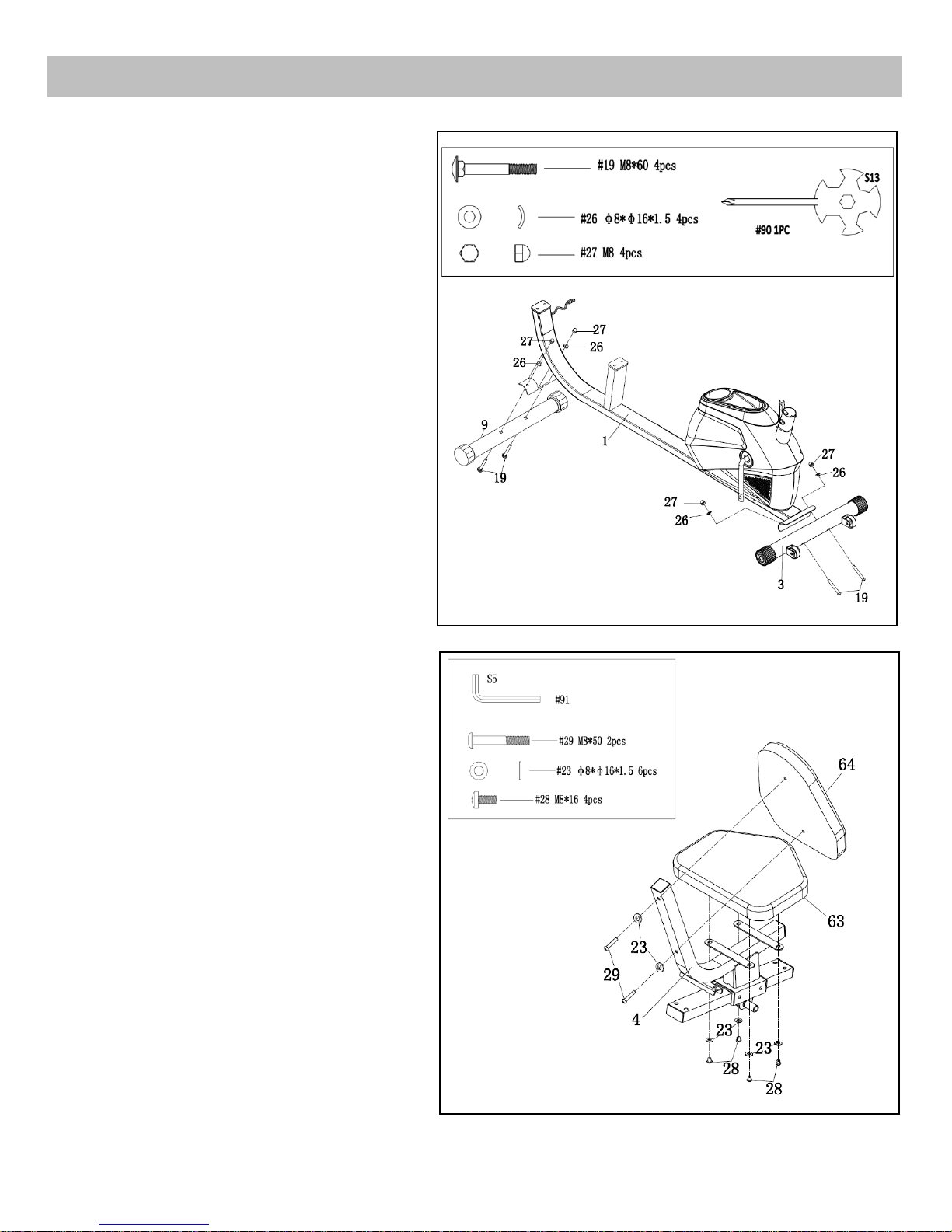
Step1:
Attach the Front Stabilizer (No.3) to the Main
Frame (No.1) using 2 Carriage Bolts (No.19), 2
Arc Washers (No.26) and 2 Cap Nuts (No. 27).
Tighten with Spanner (No.90).
Attach the Rear Stabilizer (No.9) to the Main
Frame (No.1) using 2 Carriage Bolts (No.19), 2
Arc Washers (No.26) and 2 Cap Nuts (No. 27).
Tighten with Spanner (No.90).
Step 2:
Attach the Seat Cushion (No.63) to the
Cushion Frame (No.4), making sure the
correct side is facing up, using 4 Bolts (No.28)
and 4 Flat Washers (No.23). Tighten with
Allen Wrench (No.91).
Attach the Backrest Cushion (No.64) to the
Cushion Frame (No.4) using 2 Bolts (No.29)
and 2 Flat Washers (No.23). Tighten with
Allen Wrench (No.91).
Page 8
8
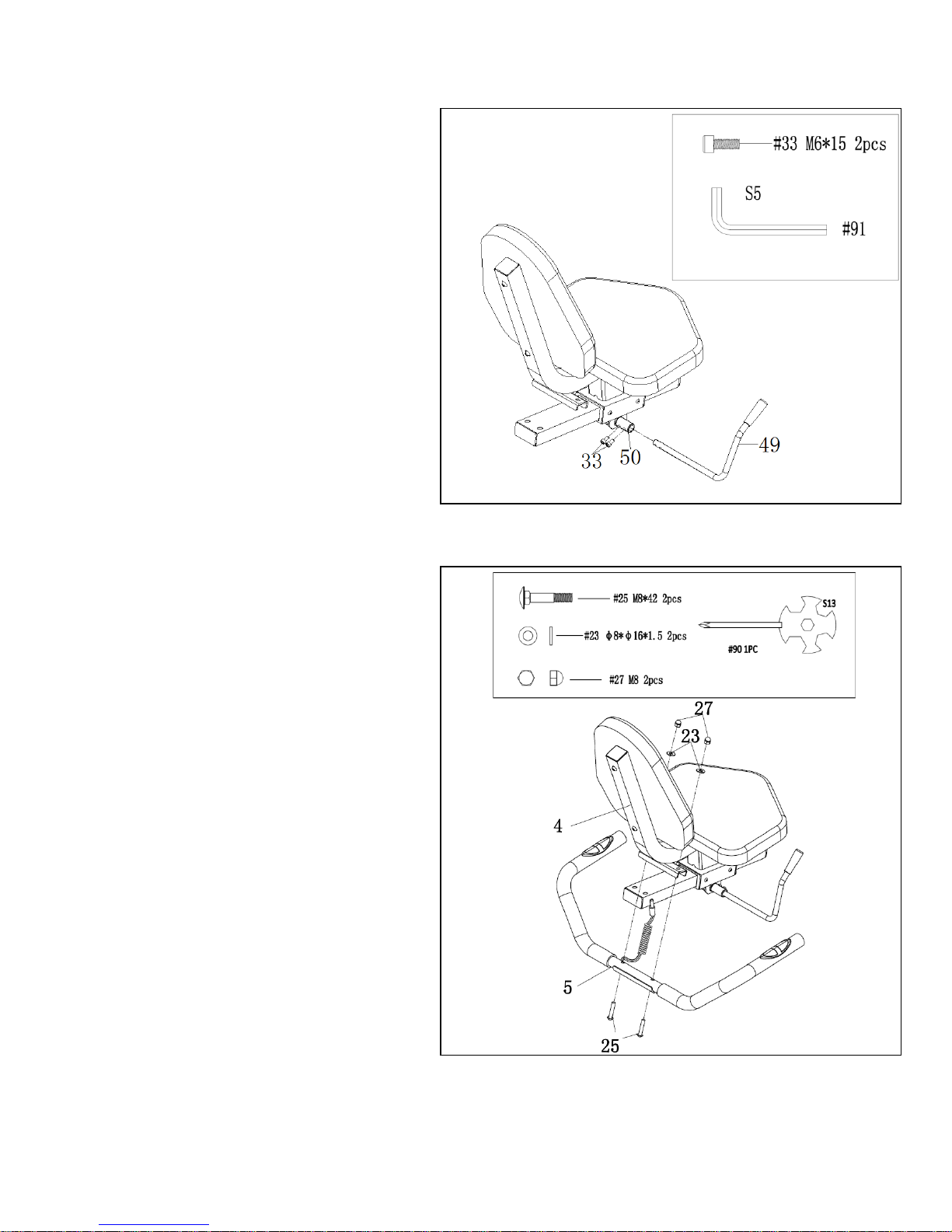
Step 3:
Insert the Brake Handle (No.49) into the hole
of Eccentric Shaft (No.50), making sure the
correct side is facing up, and then lock with 2
Screws (No.33). Tighten with Allen Wrench
(No.91).
Step 4:
Attach the Handlebar (No.5) to the Cushion
Frame (No.4) using 2 Carriage Bolts (No.25),
2 Flat Washers (No.23) and the 2 Cap Nuts
(No.27). Tighten with Spanner (No.90).
Page 9
9
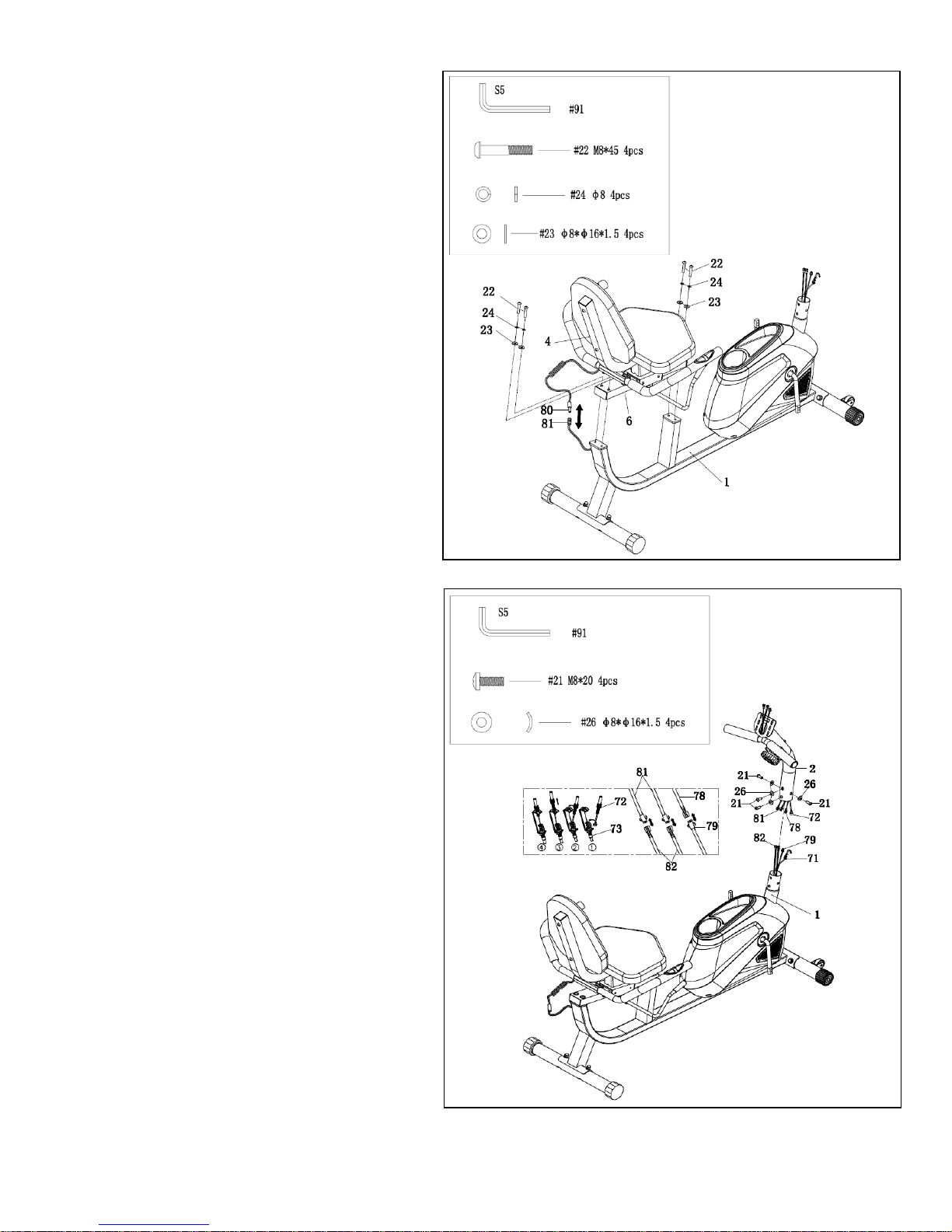
Step 5:
Attach the Cushion Frame (No.4) to the
Main Frame (No.1) using 4 Bolts (No.22), 4
Spring Washers (No.24), and 4 Flat Washers
(No. 23). Tighten with Allen Wrench (No.91).
Then connect the Hand Pulse Sensor (No.80)
with the Hand Pulse Wire (No.81).
Step 6:
Set the Tension Knob (No.72) at level 1 to
ensure the wire is at its longest length. Insert
the wire of Tension Knob (No.72) to Tension
Wire (No.73) as shown. Then connect the
Trunk Line (No.78) with the Needle Sensor
Line (No.79) and connect 2 Hand Pulse
Wires (No.81) with 2 Hand Pulse Wires
(No.82) as shown.
Attach the Front Post (No.2) to the Main
Frame (No.1), making sure align the screw
holes, using 4 Bolts (No.21) and 4 Arc
Washers (No.26), tighten with Allen Wrench
(No.91).
Page 10
10
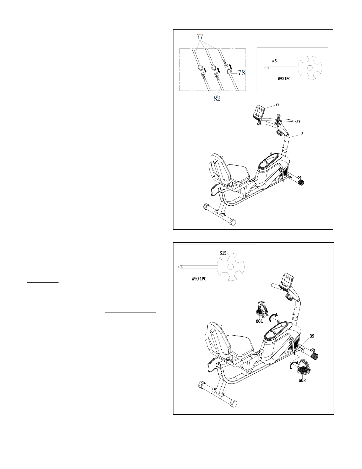
Step 7:
Connect 3 lines of Computer (No.77) with 2
Hand Pulse Wires (No.82) and Trunk Line
(No.78) in turn. Then attach the Computer
(No.77) to the Front Post (No.2) using 2
Bolts (No.37). Tighten with Spanner (No.90).
Step 8:
Connect the Pedals (No.60L/R) onto the
Crank (No.39).
Left Pedal: Align the Left Pedal (No.60L)
with the Left Crank Arm (No.39) at 90
degrees and gently insert the pedal into the
crank arm. Turn the pedal counter-clockwise
as tightly as you can with your hand then
secure with Spanner (No.90).
Right Pedal: Align the Right Pedal (No.60R)
with the Right Crank Arm (No.39) at 90
degrees and gently insert the pedal into the
crank arm. Turn the pedal clockwise as
tightly as you can with your hand then
secure with Spanner (No.90).
Assembly is complete!
Page 11
11
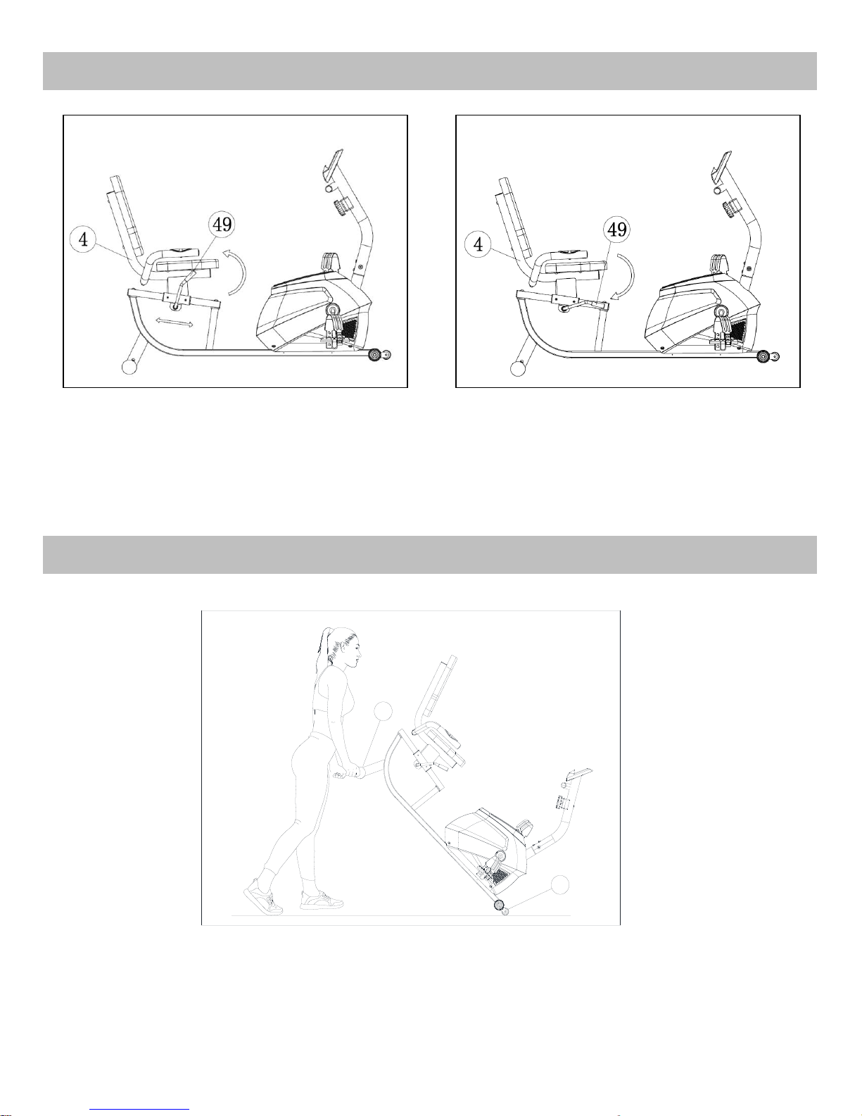
Fig. 1 Fig. 2
Pull the Brake Handle (No.49) up to loosen (Fig 1). Keep your feet on the floor as leverage, then
move the Cushion Frame (No.4) to the desired position. Push the Brake Handle (No.49) down to
tighten (Fig 2).
9
3
Hold the Rear Stabilizer (No.3) and lift the bike until wheels on the Front Stabilizer (No.9) touch the
ground. Now you can wheel the bike to the desired location.
ADJUSTING THE SEAT
HOW TO MOVE THE BIKE
Page 12
12
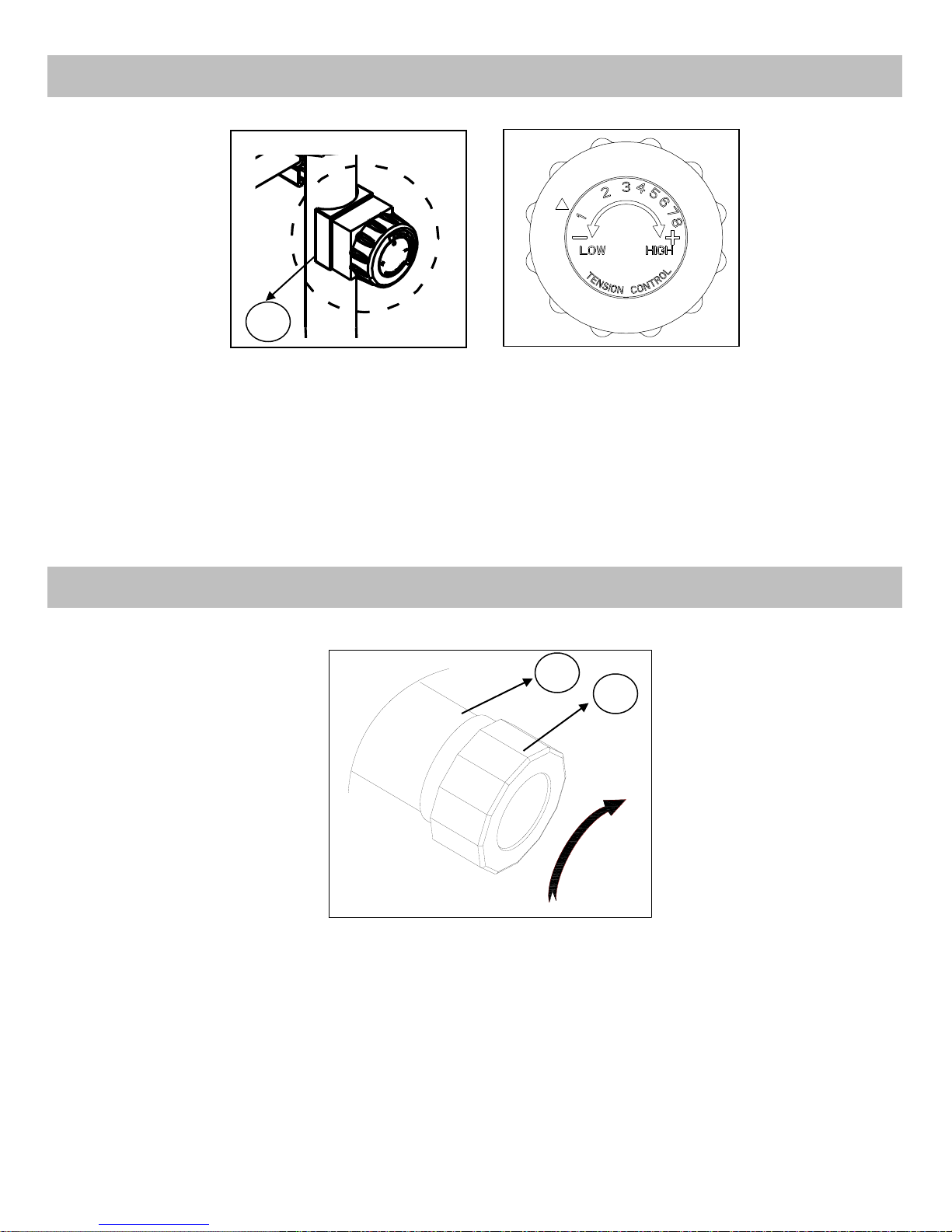
Adjust the resistance of the bike using the Tension Knob (No.72). Increase the level of resistance by
turning the tension knob to the RIGHT (clockwise), decrease the level of resistance by turning the
tension knob to the LEFT (counter-clockwise).
In order to achieve a smooth and comfortable ride, you must ensure that the bike is stable. If you
notice that the bike is unbalanced during use, you should adjust the End Caps (No.58) located
beneath the Rear Stabilizer (No.9). To do so, turn it clockwise.
ADJUSTING THE RESISTANCE
ADJUSTING THE HEIGHT AND BALANCE
58
72
9
Page 13
13
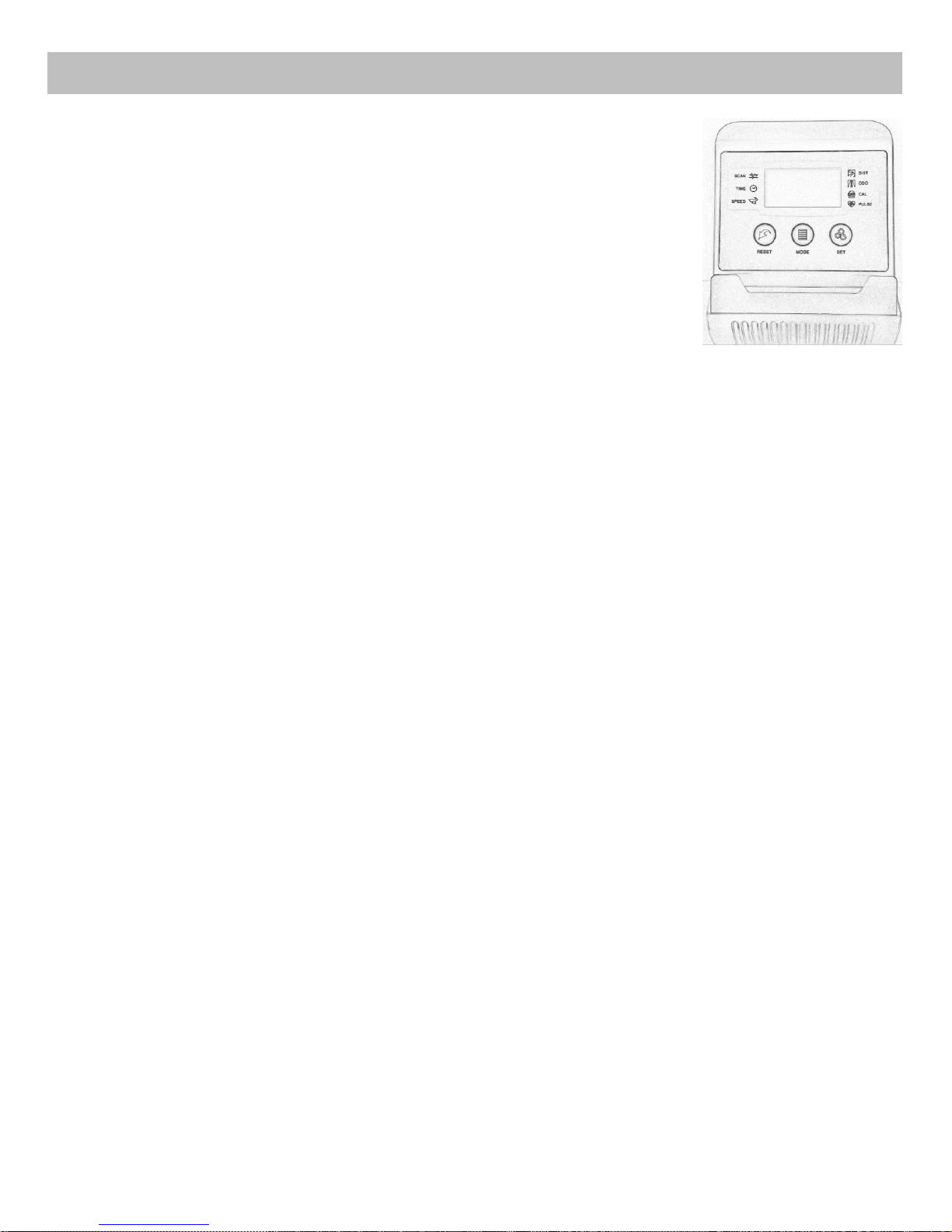
FUNCTION BUTTONS:
MODE: Press to select functions.
SET: Press to set values of time, distance, calories, or pulse when not in SCAN mode.
RESET: Press to reset time, distance and calories to zero when not in SCAN mode.
Press and hold for a few seconds to reset all values.
AUTO ON/OFF
To turn on the meter, start pedaling or press any key.
After approximately 4 minutes of inactivity, the monitor will turn off.
This meter can (1) count the value from this workout (2) countdown from a value you set.
OPERATION PROCEDURES:
SCAN: Press MODE until pointer points to SCAN. Display will rotate through all 6 functions: Time, Speed,
Distance, Calorie, ODO and Pulse. Pointer will point to the function being displayed. Each function will
display for 4 seconds. If you want to view a specific function, press MODE until pointer points to
function you want.
TIME: Displays time of your exercise session.
SPEED: Displays current speed.
DISTANCE: Displays distance you have pedaled.
CALORIES: Displays the approximate number of calories burned.
ODOMETER: Displays the total accumulated distance. Pressing RESET does not reset the odometer. Taking out
the batteries resets the odometer.
PULSE: Press MODE until pointer points to PULSE. Before measuring your pulse rate, place the palms of your
hands on both contact pads and the monitor will show your current heart beat rate in beats per minute (BPM)
on the LCD after 6~7 seconds.
During the process of pulse measurement, the measurement value may be higher than the virtual pulse rate
during the first 2~3 seconds, then will return to normal level. The measurement value cannot be regarded as
the basis of medical treatment.
COUNTDOWN FUNCTION:
The meter has a countdown function for TIME, DISTANCE, and CALORIES. To use the countdown function, press
MODE to select TIME, DISTANCE or CALORIES. Press SET to set the value. You can start pedaling. The meter will
countdown from the value you set. When the countdown is done, it will automatically start counting from 0.
COMPUTER INSTRUCTIONS
Page 14
14
NOTE: If the display is faint or shows no figures, replace the batteries. When you replace batteries, replace
both at the same time. Do not mix battery types. Do not mix old and new batteries. Dispose old batteries
according to your state and regional guidelines.
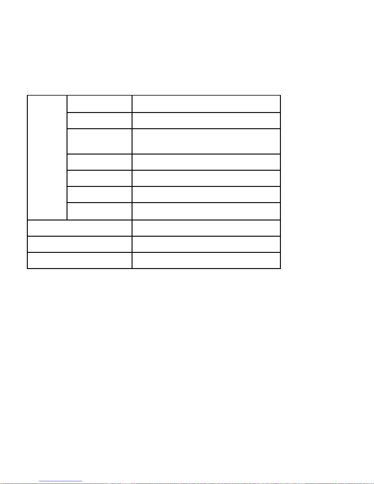
SPECIFICATIONS:
FUNCTION
AUTO SCAN
Every 4 seconds
TIME
00:00’~99:59’
CURRENT SPEED
The maximum signal can be pickup is 99.9
MI/H
TRIP DISTANCE
0.00~99.99 MI or 0.00~9999 MI
CALORIES
0.1~999.9 KCAL
ODO
0.1~999.9 MI or 1 ~ 9999 MI
PULSE RATE
40~206 BPM
BATTERY TYPE
2pcs of SIZE –AAA or UM –4
OPERATING TEMPERATURE
0°C ~ +40°C (32°~104℉)
STORAGE TEMPERATURE
-10°C ~ +60°C (-14°~140℉)
V 1
 Loading...