

Page 1
1
PRO BELT DRIVE INDOOR CYCLE
BIKE WITH MONITOR
MODEL NO.:
IC028
IMPORTANT! Read
all instructions
carefully before
using this product.
Save this manual for
future reference.
USER MANUAL
Page 2

2
At Efitment your safety is our top priority and to make sure both you and the unit remain in perfect working
order, we encourage you to read all the instructions before assembling and using your new Efitment machine.
Do not skip, substitute or modify any steps or procedures herein, as doing so could result in personal injury
and will void your warranty.
IMPORTANT SAFETY INSTRUCTIONS
1. Before starting any exercise program you
should consult your physician to determine if
you have any medical or physical conditions
that could put your health and safety at risk or
prevent you from using the equipment
properly. Your physician’s advice is essential if
you are taking any medication that may affect
your heart rate, blood pressure, or cholesterol
level.
2. Be aware of your body’s signals. Incorrect or
excessive exercise can damage your health.
Stop exercising if you experience any of the
following symptoms: pain, tightness in your
chest, irregular heartbeat, shortness of breath,
lightheadedness, dizziness, or feelings of
nausea. If you experience any of these
conditions, you should consult your physician
before continuing with your exercise program.
3. This equipment is intended for adult use only.
Keep children and pets away from the
machine. DO NOT leave children unattended
in the same room with the equipment.
4. Use the equipment on a solid, flat level
surface with a protective cover for your floor
or carpet. To ensure safety, the equipment
should have at least 2 feet of free space all
around it.
5. Check if you have all the components and tools
listed. Please note that some components are
pre-assembled to help make the assembly
process quick and easy.
6. Always use the equipment as intended. If you
find any defective components while
assembling or checking the equipment, or if you
hear any unusual noises coming from the
equipment during exercise, discontinue use
immediately and do not use until the problem
has been rectified.
7. Always wear appropriate workout clothing
when exercising. Do not wear clothing that
can get tangled in the equipment.
8. Keep hands and other objects away from all
moving parts.
9. The maximum user’s weight is 300 lbs/136 kgs.
10. Be careful when lifting and moving the
equipment. Always use proper lifting technique
and seek assistance if necessary.
11. Your equipment is intended for use in cool, dry
conditions. You should avoid storage in extreme
cold, hot, or damp areas as this may lead to
corrosion and other related problems.
12. This equipment is designed and intended for
indoor use only, not for commercial use.
SAVE THESE INSTRUCTIONS
Page 3
3
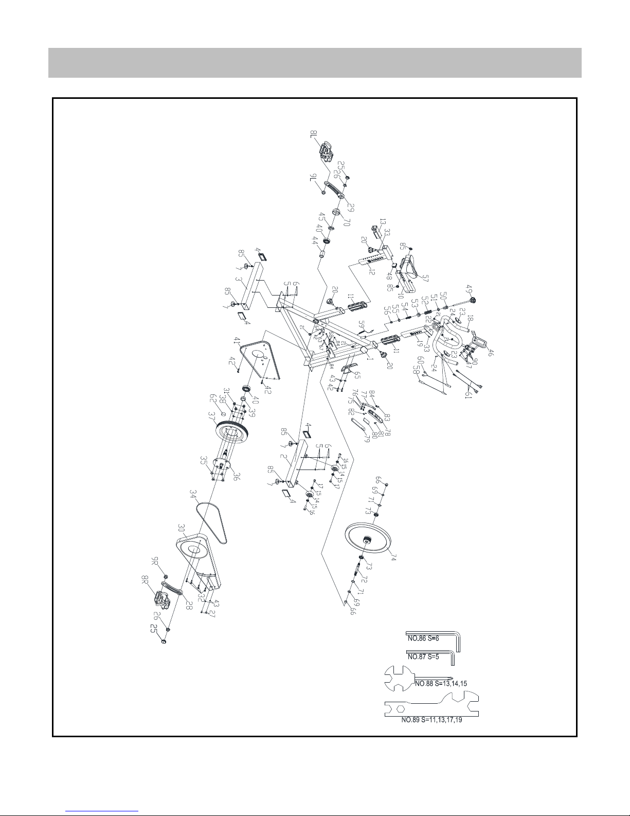
EXPLODED DRAWING
Page 4
4
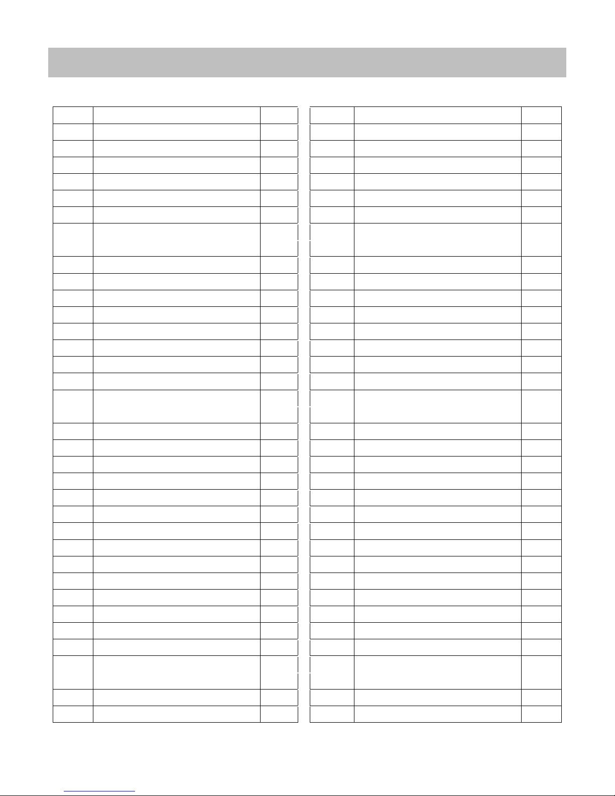
NO.
Description
Qty. NO.
Description
Qty.
1
Main Frame
1 37
Belt Wheel Φ200*18
1
2
Front Stabilizer
1 38
Elastic Washer GB/T 859-1987 8
4
3
Rear Stabilizer
1 39
Spacer Φ30*Φ25.05*9
1
4
Tube Plug material:PP
4 40
Bearing 6005ZZ
2
5
Flat Washer GB/T 95-2002 Φ8
4 41
Left Belt Cover 500*13*284
1
6
Bolt M8*65
4 42
Screw GB/T 15856.1-2002 ST4.2X19
5
7
Foot Pad Φ52*43
4 43
Flat Washer GB/T 95-2002 Φ5
4
8 L/R
Pedal JD-301(9/16")
1 SET 44
Spacer Φ30*Φ25.05*41.1
1
9 L/R
Nut 9/16"
1 SET 45
Nut M25*1
1
10
Seat Slider
1 46
Meter JS10372
1
11
Bushing material:PP
2 47
Bolt M5*10
4
12
Seat Post
1 48
Tube Plug material:PP
1
13
Bushing material:PP
1 49
Brake Knob M10*225
1
14
Transport Wheel φ69X26
2 50
Plastic Sleeve material:PA6
1
15
Bearing 608ZZ
4 51
Flat Washer Φ16*Φ10.2*1.5
1
16
Screw M6
2 52
Spring δ1.8X40
1
17
Bolt M6*12
2 53
Square Nut 16.0*16.0*δ8(M10)
1
18
Handlebar
1 54
Spring Φ1.0X55
1
19
Handlebar Post
1 55
Flat Washer Φ14*Φ6*2.5
1
20
Knob φ59*80.5(M16*1.5)
3 56
Domed Nut GB/T 802-1988 M6
1
21
Plastic Plug Φ14*14
5 57
Seat KX004
1
22
Bolt M10*20
2 58
Sensor Wire 1 L=420
1
23
Pulse Sensor LT16
2 59
Sensor Wire 2 L=1400
1
24
Screw GB/T 845-1985 ST4.2X25
2 60
Pulse Wire 1 L=420
1
25
Plastic Plug Φ28*6.5
2 61
Pulse Wire 2 L=700
2
26
Hexagon Flange Nut M12X1.25
2 62
Magnet c-02Z
1
27
Bolt GB/T 5780-2000 M4*12
2 63
Sensor SR-212
1
28
Right Crank 9/16"
1 64
Inductor Seat LTF8163
1
29
Left Crank 9/16"-LH
1 65
Bottle Holder Φ6
1
30
Right Belt Cover 700*46*288
1 66
Domed Nut M12X1.25
2
31
Nut GB/T 889.1-2000 M8
4 67
Bolt M6*70
2
32
Screw GB/T 845-1985 ST4.2*13
4 68
Hexagon Nut GB/T 41-2000 M6
2
33
Screw ST4.8*16
2 69
Flat Washer GB/T 95-2002Φ12
2
34
Belt 3PL1320mm
1 70
Decorative Cover Φ59*35
1
35
Bolt GB/T 70.3-2000 M8*18
4 71
C Clip GB894.1 Φ17
2
36
Middle Axle Φ25*167
1 72
Bottom Bracket Axle Φ17*130
1
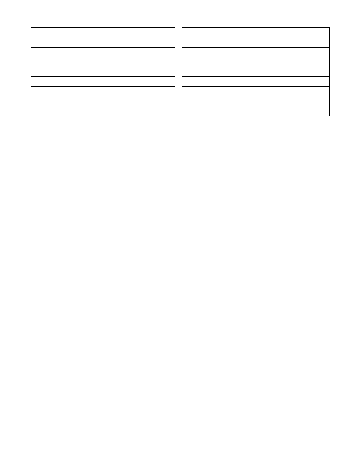
PARTS LIST
Page 5
5
73
Bearing 6203ZZ
2 82
Bolt GB/T 70.3-2000 M6*25
1
74
Flywheel 22kg
1 83
Bolt GB/T 70.1-2000 M6*12
1
75
Bolt GB/T 5780-2000 M5*10
2 84
Nut GB/T 889.1-2000 M6
3
76
Elastic Washer GB/T 859-1987 5
2 85
Hexagonal Nut
6
77
Metal Piece δ1.5
1 86
Inner Hexagon Spanner S=6
1
78
Brake Block 163.2*30*17.5
1 87
Inner Hexagon Spanner S=5
1
79
Cow Leather Pad 157*26.5*5.5
1 88
Crosshead Spanner S=13,14,15
1
80
Eva Pad 60*26.5*t3.5
1 89
Open Wrench S=11,13,17,19
1
81
Bolt GB/T 70.3-2000 M6*18
1 90
Flat Washer Φ12*Φ4.5*1
4
Page 6
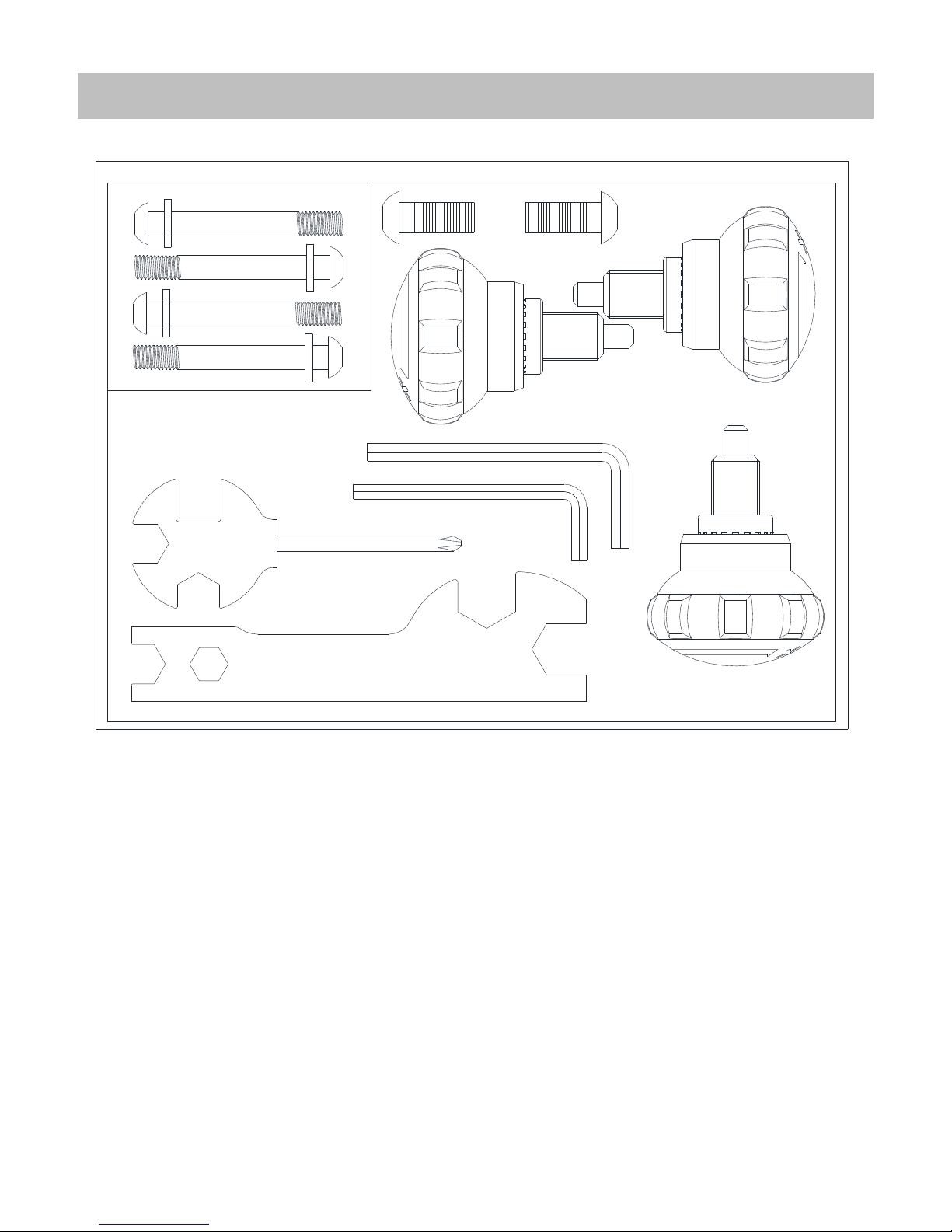
6
HARDWARE PACKAGE
Tools & Accessories
NO.06
NO.20
NO.22
NO.20
NO.20
NO.86
NO.87
NO.88
NO.89
NO.05
Page 7
7
PREPARATION BEFORE STARTING ASSEMBLY:
A. Make sure that you have adequate work space around the item.
B. Use the hardware package provided when assembling unit.
C. Confirm all necessary parts and tools are available (Note: Instruction Sheet above will have an
exploded drawing with all single parts marked with numbers).
:
ASSEMBLY INSTRUCTIONS
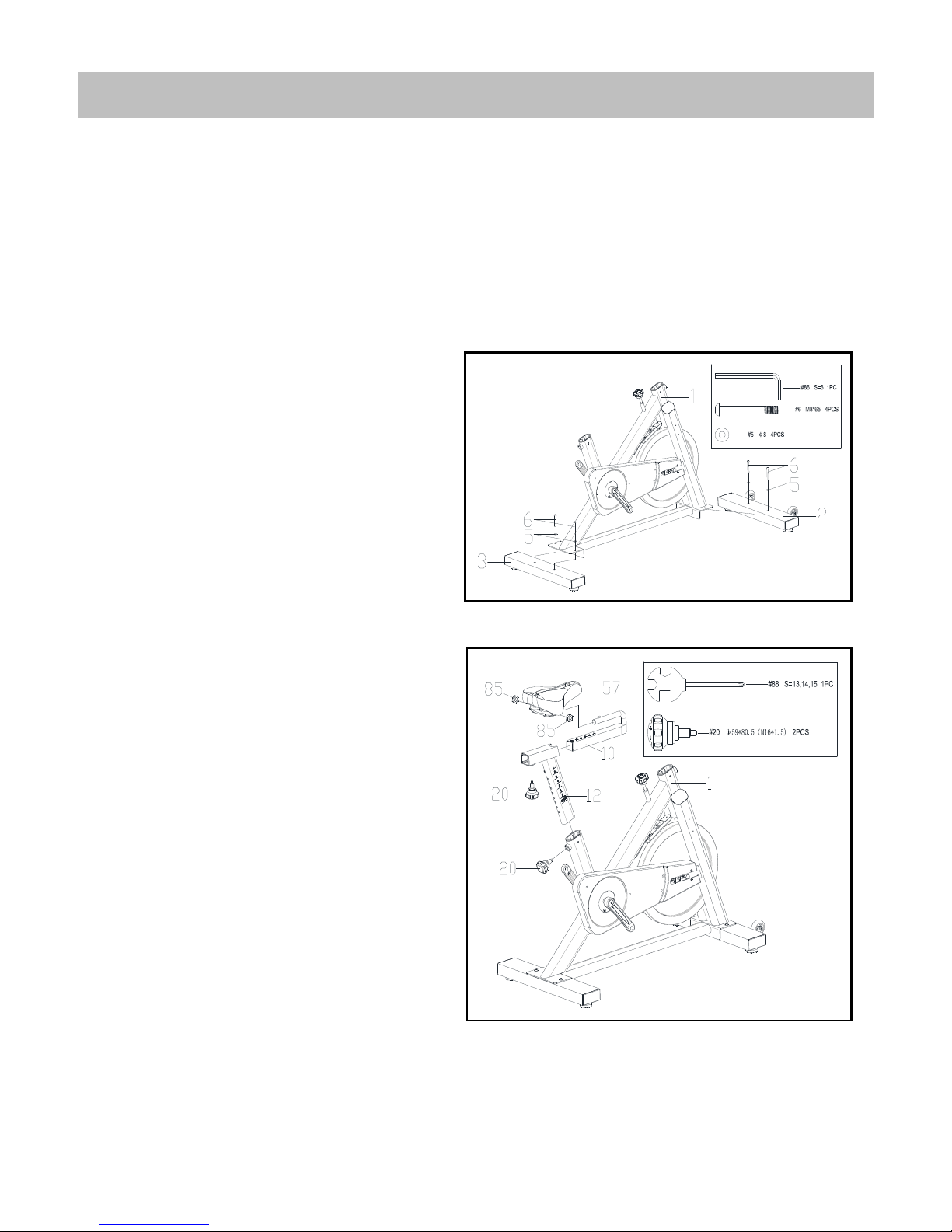
Step 1:
Attach Front & Rear Stabilizers (No.2 & 3) to
the Main Frame (No.1) with 4 Bolts (No.6)
and 4 Flat Washers (No.5). Tighten with an
Inner Hexagon Spanner (No.86).
Step 2:
Insert the Seat Post (No.12) into the Main
Frame (No.1). Set at desired height, insert
and tighten the Knob (No.20).
Insert the Seat Slider (No.10) into the Seat
Post (No.12). Set at desired position, insert
and tighten the Knob (No.20).
Attach the Seat (No.57) to Seat Slider (No.10)
using the 2 Hexagonal Nuts (No.85). Tighten
with a Crosshead Spanner (No.88).
Page 8
8
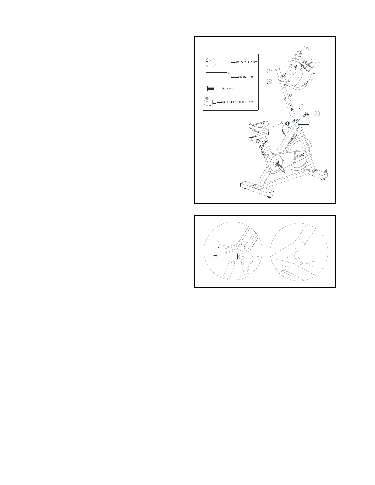
Step 3:
Insert the Handlebar Post (No.19) into the
Main Frame (No.1). Set at desired height,
insert and tighten the Knob (No.20).
Attach the Handlebar (No.18) to the
Handlebar Post (No.19) with 2 Bolts (No.22).
Tighten with an Inner Hexagon Spanner
(No.86).
Remove 4 Bolts (No.47) and 4 Washer (No.90)
from Meter (No.46). Attach the Meter
(No.46) into the Handlebar (No.18) using the
4 Bolts (No.47) and 4 Washer (No.90) that are
removed. Tighten with a Crosshead Spanner
(No.88). Then connect plug A1 to plug A2,
plug B1 to plug B2, plug C1 to plug C2.
Page 9
9
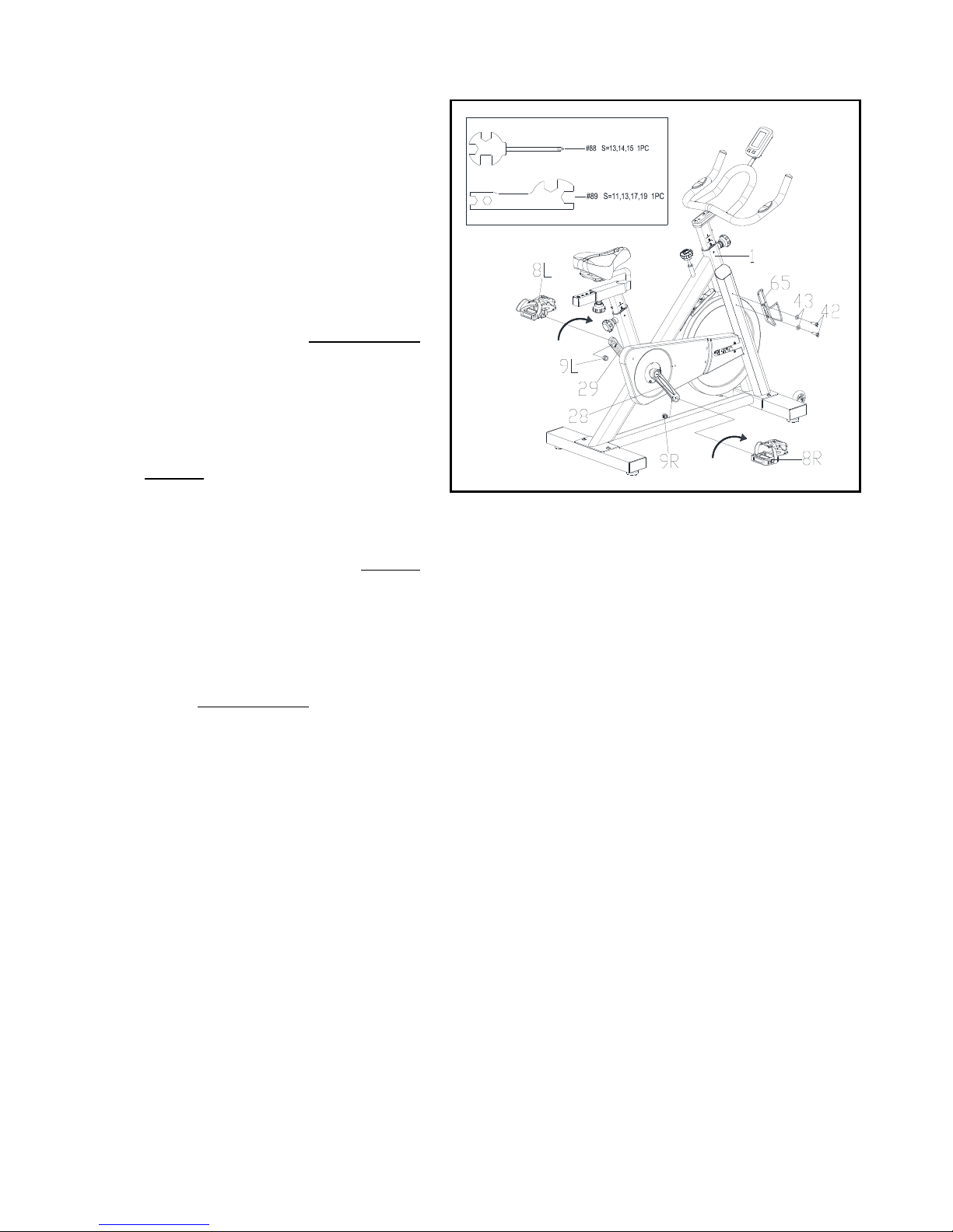
Step 4:
The Pedals (No.8L/R) are marked "L" and "R" for
Left and Right. Make sure you attach the correct
pedal to the corresponding crank. Attaching the
pedal to the wrong crank can cause irreversible
damage to both the pedal and the crank. The
Nuts (No.9L/R) are preassembled to Pedals
(No.8L/R).
Attach Left Pedal (No.8L) to Left Crank (No.29).
Turn the Left Pedal (No.8L) counter-clockwise
with the hand until it is tight, then use the
Crosshead Spanner (No.88) to securely tighten.
Use the Crosshead Spanner (No.88) to hold the
bolt of the pedal in place, then use the Open
Wrench (No.89) to screw the Nut (No.9L) tightly
in a clockwise direction to the thread end of the
Left Pedal (No.8L).
Attach Right Pedal (No.8R) to Right Crank
(No.28). Turn the Right Pedal (No.8R) clockwise
with the hand until it is tight, then use the
Crosshead Spanner (No.88) to securely tighten.
Use the Crosshead Spanner (No.88) to hold the
bolt of the pedal in place, then use the Open
Wrench (No.89) to screw the Nut (No.9R)
tightly in a counter-clockwise direction to the
thread end of the Right Pedal (No.8R).
Remove 2 pre-assembled Screws (No.42) and 2
pre-assembled Flat Washers (No. 43) from the
Main Frame (No.1). Then attach the Bottle
Holder (No.65) to the Main Frame (No.1) using
the 2 Screws (No.42) and 2 Flat Washers
(No.43) that are removed. Tighten with a
Crosshead Spanner (No.89).
Assembly is complete!
Page 10
10
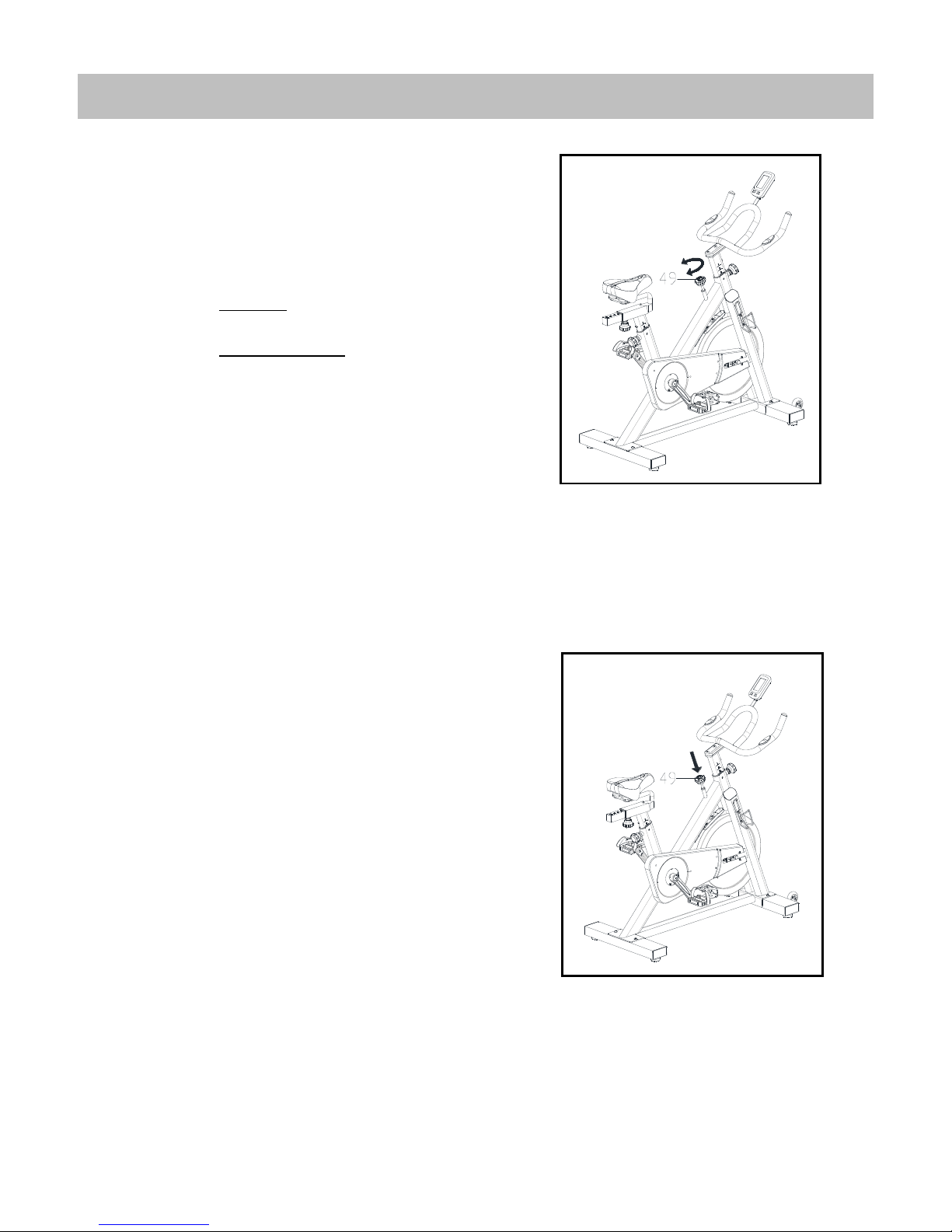
TENSION ADJUSTMENT
A. Adjusting the Tension:
Increasing or decreasing the tension allows
you to add variety to your workout
sessions.
To increase the tension, turn the Brake
Knob (No.49) clockwise.
To decrease the tension, turn the Brake
Knob (No.49) counter-clockwise.
B. Emergency Brake Function:
The Brake Knob (No.49) is also the
emergency brake. Use this safety feature
in situations where you need to get off the
bike or stop the bike’s flywheel.
During exercise, firmly press down on the
Brake Knob (No.49) to stop the bike
immediately.
Page 11
11
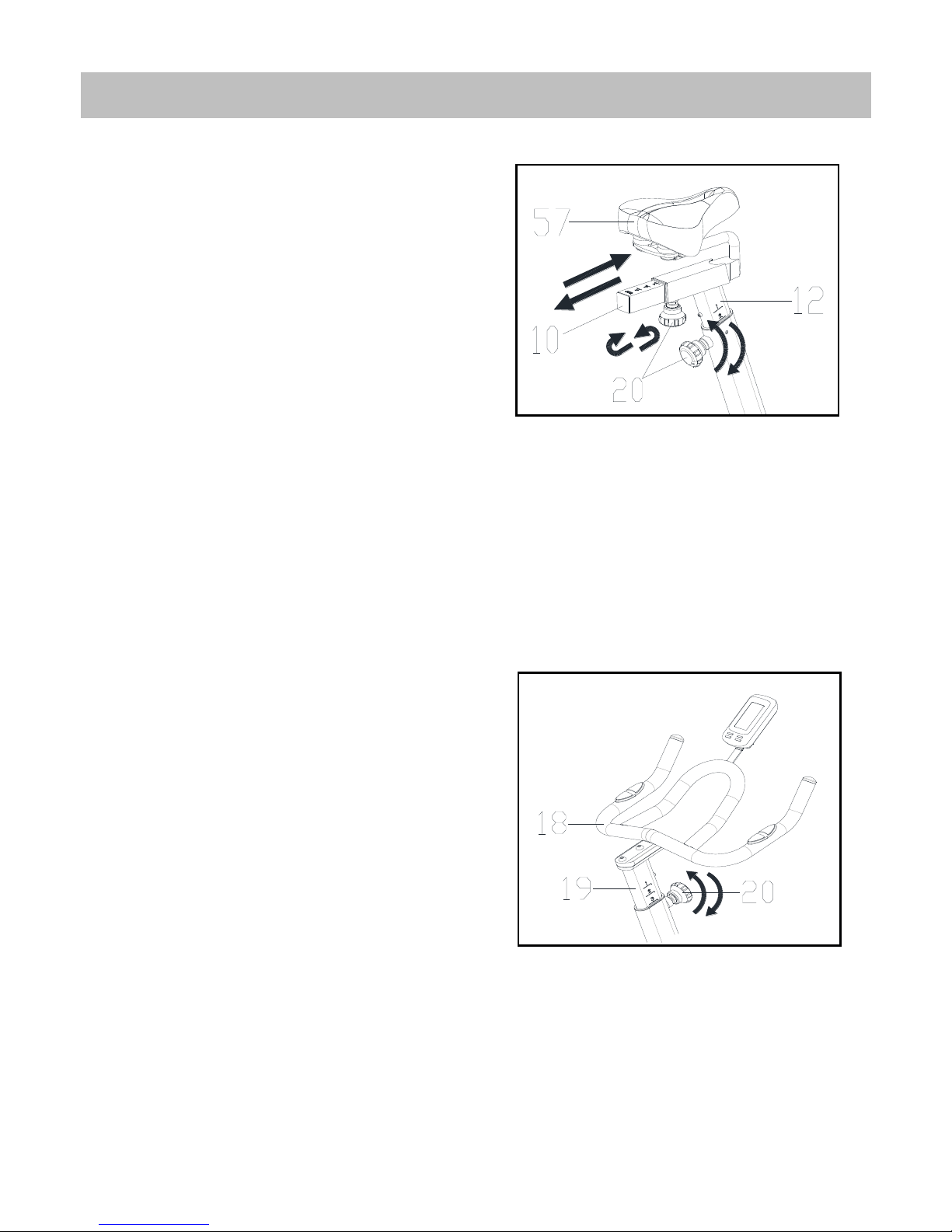
SEAT AND HANDLEBAR ADJUSTMENT
The seat of this bike is fully adjustable
as it moves Up, Down, Forward and
Backward.
A. To adjust the height of the Seat Post
(No.12), loosen and pull on the [Seat
Post] Knob (No.20), then raise or lower
the Seat (No.57) to the desired height.
Once adjusted, tighten the [Seat Post]
Knob (No.20) to secure the Seat (No.57)
in place.
B. To adjust the Seat (No.57) forward
and backward, loosen and pull on the
[Seat Slider] Knob (No.20), then slide
the Seat Slider (No.10) to the desired
position. Once positioned, tighten the
[Seat Slider] Knob (No.20) to secure the
Seat Slider (No.10) in place.
C. To adjust the height of Handlebar
(No.18), loosen and pull on the
[Handlebar Post] Knob (No.20), then
slide the Handlebar Post (No.19) up or
down to the desired height. Once
adjusted, tighten the Knob (No.20) to
secure the Handlebar Post (No.19) in
place.
Page 12
12
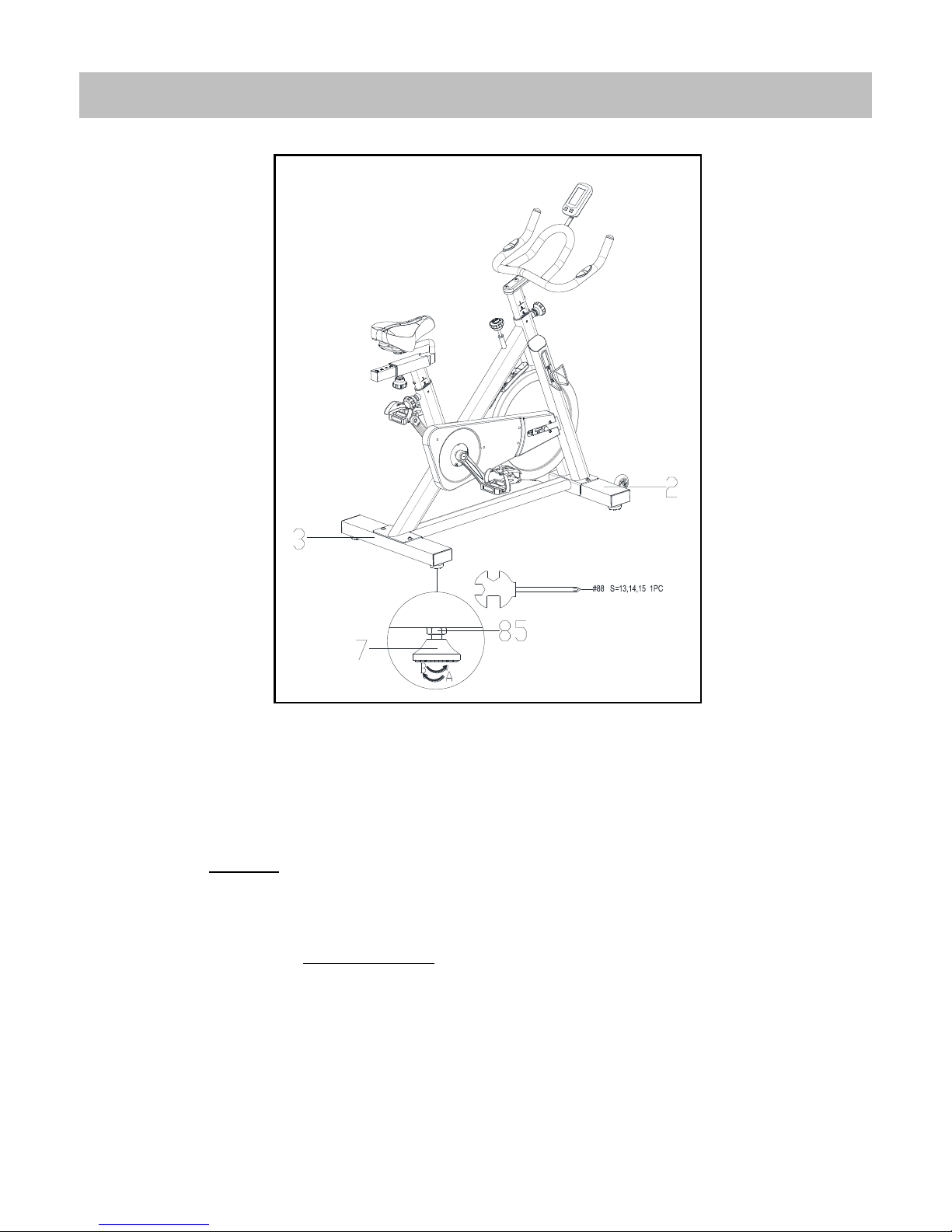
BALANCE ADJUSTMENT
To achieve a smooth and comfortable experience, you must ensure that the bike is stable.
During use, if you notice that the bike is unbalanced, you can adjust the Foot Pads (No.7)
located beneath the Front & Rear Stabilizers (No.2 & 3).
To adjust, use the Crosshead Spanner (No.88) to loosen the Hexagonal Nut (No.85) by
turning it clockwise (A). With the nut loosened, rotate the Foot Pad (No.7) until it sits level
with the surface that the bike is on.
When you have finished adjusting the Foot Pad (No.7), re-tighten the Hexagonal Nut
(No.85) by turning it counter-clockwise (B) using Crosshead Spanner (No.88). If needed,
repeat this process to adjust the remaining Foot Pad (No.7).
Page 13
13
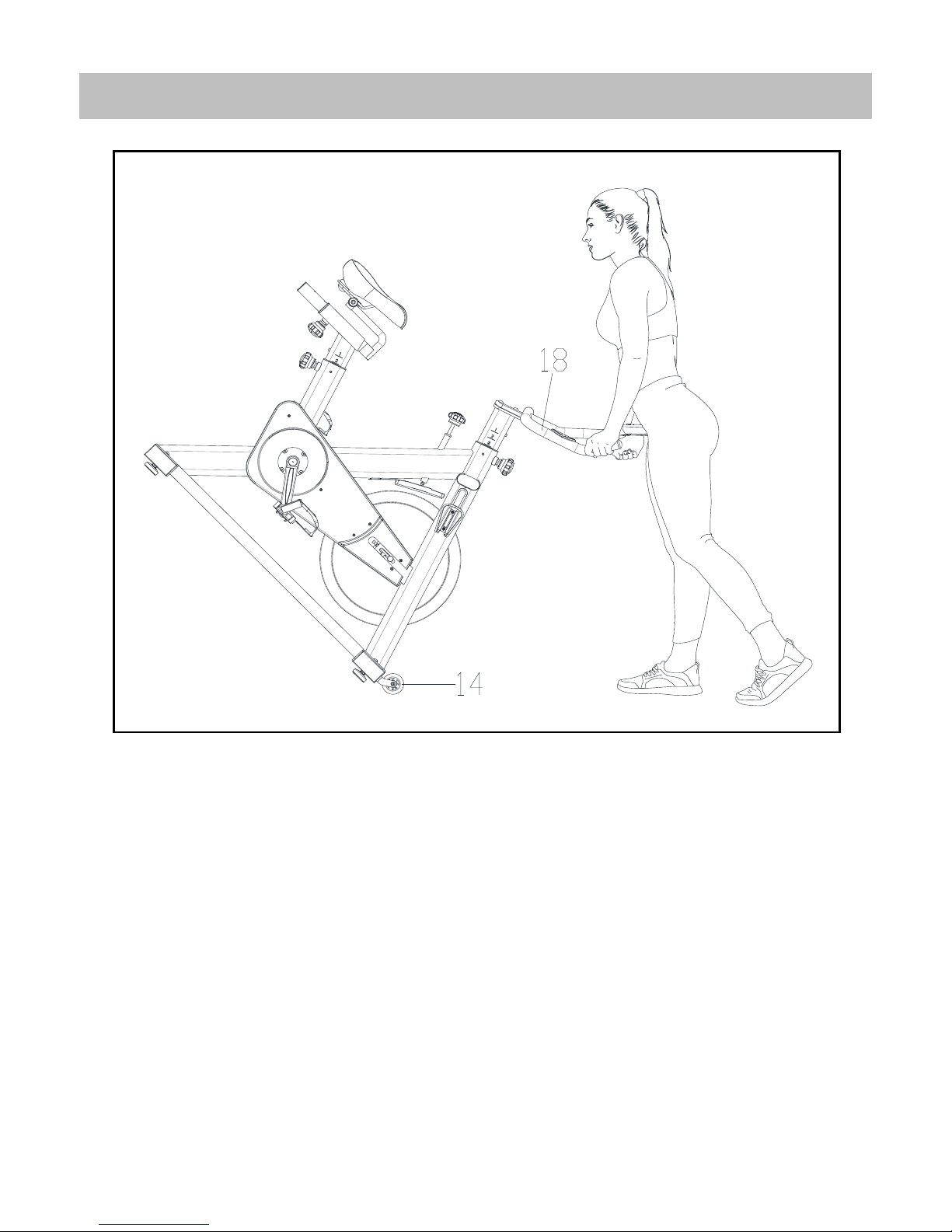
HOW TO MOVE THE BIKE
Firmly grasp and hold each side of the Handlebar (No.18). Place one foot on the front base and
tilt the bike towards you until the Transport Wheels (No.14) on the front base touch the
ground. With the Transport Wheels (No.14) on the ground, you can transport the bike to the
desired location with ease.
Page 14
14
FUNCTIONAL BUTTONS:
1. MODE
Press to select functions (TIME/DIST/CAL).
When exercise, the icon “ ” will display. Press to enter scan function (with
icon “ ”) The meter will display SPEED/AVG SPEED/ MAX SPEED, CALORIES/
RPM, PULSE/AVG PULSE.
Hold for 2 seconds to reset all data.
2. SET
Press to set values of time, distance, calories. Hold for quick increase.
Press to scan (with icon “ ”) the SPEED/AVG SPEED/MAX SPEED, CALORIES/
RPM, PULSE/AVG PULSE/MAX PULSE.
3. RESET
During SET, press RESET to to reset time, distance, calories.
4. RECOVERY
Press to enter pulse recovery function when heart rate displays.
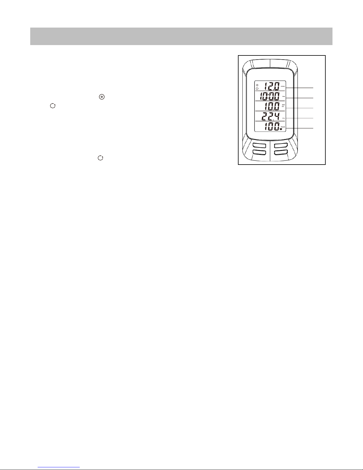
FUNCTION:
1. Window A displays SPEED, AVG SPEED, MAX SPEED during exercise.
2. Window B displays TIME (range: 00:00~99:59).
① Counts the total time of the exercise from start to finish.
② Exercise time can be set. When it countdowns to zero, the TIME will flash and beep for 5 seconds.
3. Window C displays DISTANCE (range: 0.0~99.9).
① Counts the distance of the exercise from start to finish.
② Exercise distance can be set. When it countdowns to zero, the DIST will flash and beep for 5 seconds.
4. Window D displays CALORIES (range: 0.0~999) and RPM.
① Counts the amount of total calories burned from start to finish.
② Display the current RPM (or cadence).
③ The calorie value can be set. When it countdowns to zero, the CAL will flash and beep for 5 seconds.
5. Window E displays PULSE (range: 40~220BPM), AVG PULSE, MAX PULSE during exercise.
6.AUTO OFF
Without any exercise signal or operation over 4 minutes, the meter will turn off automatically and memorize
the current data.
METER INSTRUCTIONS
A B C
D
E
Page 15

15
OPERATION:
1. SET THE TARGET PARAMETERS
When stop exercise, press MODE to set TIME→DIST→CAL. The corresponding window will display SET, then
press SET to set the flashing window’s value. Hold the button to quick increase. You can press RESET to clear
the value.
2. CHECK THE EXERCISE DATA
① In non-set mode, press SET or during exercise, the icon “ ” will display. Press MODE to separately check
the SPEED/AVG SPEED/MAX SPEED, CALORIES/RPM, PULSE/AVG PULSE/MAX PULSE.
② When icon displays “ ” , the meter will scan the value in corresponding window every 6 seconds.
REPLACE BATTERY
The meter uses 2pcs new 1.5V AAA UM-4 battery. When the display color fades, or with flash when operate
buttons, please install new batteries. Always change both batteries at the same time. Do not mix battery types
and do not mix old and new batteries. Dispose batteries according to your state and regional guidelines.
V1
 Loading...