

Premier Belt Drive Indoor Cycling Bike: IC014
PLEASE READ THIS MANUAL CAREFULLY BEFORE USING THE BIKE.
For Customer Service, please contact: service@efitment.com

IMPORTANT SAFETY INFORMATION
We thank you for choosing our product. To ensure your safety and health, please use this equipment
correctly. It is important to read this entire manual before assembling and using the equipment. Safe
and effective use can only be achieved if the equipment is assembled, maintained and used properly.
It is your responsibility to ensure that all users of the equipment are informed of all warnings and
precautions.
1. Before starting any exercise program you should consult your physician to determine if you have
any medical or physical conditions that could put your health and safety at risk, or prevent you
from using the equipment properly. Your physician’s advice is essential if you are taking
medication that affects your heart rate, blood pressure or cholesterol level.
2. Be aware of your body’s signals. Incorrect or excessive exercise can damage your health. Stop
exercising if you experience any of the following symptoms: pain, tightness in your chest, irregular
heartbeat, and extreme shortness of breath, lightheadedness, dizziness or feelings of nausea. If
you do experience any of these conditions, you should consult your physician before continuing
with your exercise program.
3. Keep children and pets away from the equipment. The equipment is designed for adult use only.
4. Use the equipment on a solid, flat level surface with a protective cover for your floor or carpet. To
ensure safety, the equipment should have at least 2 feet of free space all around it.
5. Ensure that all nuts and bolts are securely tightened before using the equipment. The safety of the
equipment can only be maintained if it is regularly examined for damage and/or ware and tear.
6. Always use the equipment as indicated. If you find any defective components while assembling or
checking the equipment, or if you hear any unusual noises coming from the equipment during
exercise, stop using the equipment immediately and don’t use the equipment until the problem
has been rectified.
7. Wear suitable clothing while using the equipment. Avoid wearing loose clothing that may become
entangled in the equipment.
8. The maximum weight capacity of this unit is 300 pounds.
9. The equipment is not suitable for therapeutic use.
10. You must take care of yourself when lifting and moving the equipment so as not to injure your back.
Always use proper lifting technique and seek assistance if necessary.
11. This equipment is designed for indoor and home use only, it is not intended for commercial use.
WARNING: This product can expose you to one or more chemicals known to
the State of California to cause cancer and birth defects or reproductive
harm. For more information go to www.P65Warnings.ca.gov.
1
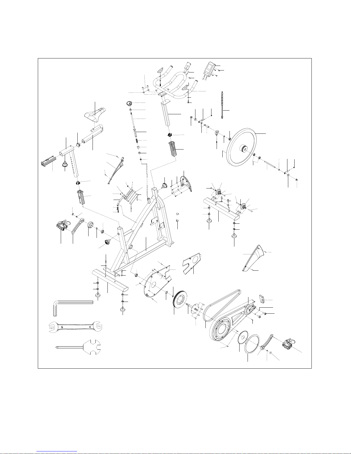
EXPLODED VIEW
8
39
40
74
74
36
36
36
74
34
34
32
32
35
38
38
38
38
7
7
1
2
7
5
12
9
54R
54L
61
63
51
51
53L
57
57
56
78
56
52
13
14
15
16
17
20
28
24
22
21
21
27
30
29
26
19
18
59
64
65
52
67
23
53R
25
37
37
37
37
33
33
33
33
11
10
4
3
60
70R
70L
69
69
69
69
71
73
5
58
12
6
58
58
5
60
45
48
44
43
42
42
31
50
49
49
41
41
31
55
72
66
37
37
37
37
#75 S6 1PC
#76 S13-15 1PC
50
77
62
68
79
80
58
81
44
42
46
47
82
83
84
85
86
87
88
89
#90 S13-S14-15 1PC
2

PARTS LIST
NO.
Description
Qty.
NO.
Description
Qty.
1
Screw M10*25*S6
2 41
Nut M8*H7.5*S13
2 2 Washer d10*φ20*1.5
2 42
Nut M12*1*H6*S19
4 3 Handlebar
1 43
Spacer Φ18*Φ12.2*11.5
1 4 Handlebar post
1 44
Bearing 6202-2RS C﹠U
3
5
End cap PTB35*41*2.5*L20
3 45
Flywheel
18*Φ460*80*30*Φ55*42*PK
1
6
Bushing PT45*51*PT35*41*L198
1 46
Inductor
1 7 Knob M16*1.5*18*Φ56
3 47
Round magnet Φ10*3 3600 gauss
1 8 Main frame
1 48
Inertial axle
1 9 Saddle
1 49
Adjusting screw
2
10
Seat slider
1 50
Washer d12*φ24*2
2
11
Saddle post
1 51
Crank cap Φ25*7
2
12
Bushing
PTB45*51*2.0*PTB35*41*L198
2 52
Nut M10*1.25*H7.5*S14
2
13
Knob φ58*44*M8*18
1 53L/R
Pedal JD-005 9/16
2
14
Nut M8*H5.5*S14
1 54 L/R
Crank 170 9/16
2
15
Brake rod
Φ10*270*M8*20*M6*7*M10*95
1 55
Cover for middle axle
Φ50*Φ32*33
1
16
Bushing 20*20*74
1 56
C clip d20
2
17
Spring Φ2.0*Φ15*54*N12
1 57
Bearing 6004-2RS
2
18
Nut 15*15*25*M10
1 58
Screw ST4.2*16*Φ8
9
19
Nut M10*H5.5*S17
1 59
Inner chain cover 438*309*17.3
1
20
Nut M6*H14*S10
1 60
Screw ST4.8*16*Φ10
2
21
Screw M5*20*Φ8.5
2 61
Wave washer d20*Φ26*0.3
1
22
Cow leather t5*25*138
1 62
Middle axle
1
23
EVA pad 10*22*95
1 63
Belt 5PK520
1
24
Brake block 12*25*138
1 64
Outer chain cover 703*315*56.5
1
25
Nut M5*H9*S8
1 65
Front cover 110*43*23
1
26
Screw M5*12*Φ10
1 66
Washer d6*Φ12*1.2
2
27
Nut M5*H4*S8
1 67
Screw M6*10*Φ12
2
28
Spring piece t2.0*15.8*153
1 68
AL616BE circleφ236*203*4
1
29
Washer d6*Φ16*1.5
2 69
Screw ST4.2*16*φ10.5
4
30
Bolt M6*16*S10
2 70L/R
Cover for cant beam
2
31
Nut M12*1*H19.5*S19
2 71
Upper cover for flywheel
1
32
Screw Φ7.8*30*M6*15*S5
2 72
Washer d5*Φ13*1
4
33
Bearing 608ZZ
4 73
Screw ST4.8*10*Φ8
4
34
Transport wheel Φ71*Φ19*24
2 74
Screw M10*25*S6
4
35
Screw M6*12*S5
2 75
Allen wrench S6
1
36
Washer d10*φ20*2.0
4 76
Open wrench S13- S15
1
37
Nut M10*H7*S17
8 77
Screw M10*16*S6
4
38
Adjustable pad M10*30*φ52*49
4 78
Belt wheel Φ204*21*5PK
1
39
Front stabilizer
1 79
AL902E-1 crank cover Φ162.8*8
1
40
Rear stabilizer
1 80
AL912S Blanking plate
1
3

NO.
Description
Qty.
NO.
Description
Qty.
81
End cap Φ22*16
2 86
Grommet Φ12
3
82
Sensor wire
1 87
Handle pulse wire
1
83
Screw ST4*19*Φ7
2 88
Screw M5*10
4
84
Washer d6*Φ12*1
2 89
Computer
1
85
Handle pulse
2 90
Spanner S14-15-17
1
4

HARDWARE PACKAGE
#90 S14-S15-17 1PC
5

ASSEMBLY INSTRUCTIONS
#74 M10*25*S6 4PCS
#36 d10*Φ20*2.0 4PCS
74
36
74
36
8
40
39
#75 S6
9
10
#76 S13-15 1PC
STEP 1:
Attach the Front and Rear Stabilizers (No. 39 and No. 40) to the Main Frame (No. 8)
using 4 Screws (No. 74) and 4 Flat Washers (No. 36). Tighten and secure with Allen
Wrench (No. 75).
Attach Saddle (No. 9) to Seat Slider (No.10), and tighten and secure with Open
Wrench (No. 76). Note: Adjust the saddle, so the front of the saddle is higher or lower
for your comfort.
6

8
53L
53R
54R
54L
#76
STEP 2:
Connect the Left and Right Pedals (No. 53L and No. 53R) to the Left and Right Crank
Arms (No. 54L and No. 54R). Before you begin, immobilize the crank arms by turning the
tension knob all the way to the right.
The Left and Right Pedals (No. 53L and No. 53R) are marked L for the left pedal and R for
the right pedal.
Left Pedal: Align the Left Pedal (No. 53L) with the Left Crank Arm (No. 54L) at 90
degrees. Gently insert the pedal into the crank arm, turn the pedal counter-clockwise as
tightly as you can with your hand. Tighten and secure with Open End Wrench (No. 76).
Right Pedal: Align the Right Pedal (No. 53R) with the Right Crank Arm (No. 54R) at 90
degrees. Gently insert the pedal into the crank arm, turn the pedal clockwise as tightly as
you can with your hand. Tighten and secure with Open End Wrench (No. 76).
7

#1 M10*25*S6 2PCS
#2 d10*Φ20*1.5 2PCS
#75 S6
4
3
7
1
2
8
STEP 3:
Loosen and remove the Adjustment Knob (No. 7). Insert the Handlebar Post (No. 4) into
the tube located on the front of the Main Frame (No. 8). Adjust the Handlebar Post (No.
4) to the desired position then secure it in place by reinserting and tightening the
Adjustment Knob (No. 7).
Attach the Handlebar (No. 3) to the Handlebar Post (No. 4) using 2 Screws (No. 1) and 2
Washers (No. 2), tighten and secure with Allen Wrench (No. 75).
8

#88 M5*10 4PCS
3
#90 S14-S15-17 1PC
88
89
87
82
89a
89b
STEP 4:
Remove the 4 Screws (No. 88) from the back of the Computer (No. 89) at first. Then
attach the Computer (No. 89) to the bracket located on the Handlebar (No. 3) using 4
Screws (No. 88). Connect the link wire of the Computer (No. 89a) with the Sensor Wire
(No. 82); connect the Handle Pulse Wire (No. 87) with the link wire of Computer (No.
89b).
The assembly is complete!
9

ADJUSTMENTS GUIDE
1. ADJUSTING THE HEIGHT AND BALANCE
In order to achieve a smooth and comfortable ride, you must ensure that the stability of the
bike is secured. If you notice that the bike is unbalanced during use, you should adjust the
foot levelers located beneath the Front and Rear Stabilizers of the bike. To do so, use
Spanner (No. 90) to loosen Nut (No. 37) by turning it clockwise (direction A). With the nut
loosened, rotate the Foot Leveler (No. 38) until it sits level with the surface that the bike is
on. When you have finished adjusting the foot leveler, use Spanner (No. 90) to re-tighten
the Nut (No. 37) by turning it counter-clockwise (direction B). If required, repeat this
process to adjust the remaining foot levelers.
10

2. ADJUSTING THE SADDLE
The seat of this bike is fully adjustable as it moves Up, Down, Fore (forward), Aft
(backward).
To adjust the height of the Saddle Post (No. 11), loosen and pull the Adjustment Knob
(No. 7) outward, then raise or lower the saddle to the desired height. Once adjusted,
re-insert and tighten the Adjustment Knob (No. 7) to secure the saddle in place.
To adjust the saddle back and forth, loosen and pull Adjustment Knob (No. 7) outward,
then slide the Seat Slider Tube (No. 10) to the desired position. Once positioned, re-insert
and tighten the Adjustment Knob (No. 7) to secure the seat slider tube in place.
3. ADJUSTING THE HANDLEBAR
It is important that the handlebar and seat are both set to the correct height of your body. To
adjust the handlebar height, loosen and pull the Adjustment Knob (No. 7) outward, then
slide the Handlebar Post (No. 4) up or down to the desired height. Once adjusted re-insert
and tighten the Adjustment Knob (No. 7) to secure the handlebar post in place.
7
11
10 7 4
11

4. PEDAL STRAP ADJUSTMENT
Your feet should be secured in the toe clips during exercise. Place your feet as far forward
into the toe-clips as you can. With your feet in place, turn the crank to bring one foot to
within arm’s reach, grasp the pedal strap and pull it upward to tighten the toe-clip cage, then
insert the strap back into the hoop of the toe-clip. Repeat this process to secure your other
foot.
5. ADJUSTING THE RESISTANCE
Adjust the resistance of the bike using the Tension Knob (No. 13). Increase the level of
resistance by turning the tension knob to the RIGHT (clockwise), decrease the level of
resistance by turning the tension knob to the LEFT (counter-clockwise).
13
12

MOVING THE BIKE & BRAKING/DISMOUNTING
1. TRANSPORTING THE BIKE
To move the bike, first ensure that the Handlebar (No. 3) is properly secured. If the
handlebar is loose, tighten the Adjustment Knob (No. 16) to secure it. Next, stand at the
front of the bike so that you’re directly in front of the handlebar. Firmly grasp and hold each
side of the handlebar, place one foot on the front stabilizer and tilt the bike towards you until
the transportation wheels on the front stabilizer touch the ground. With the wheels on the
ground, you can transport the bike to the desired location with ease.
NOTE: When moving the bike, always move with caution as unexpected impact, such as
dropping the bike, may cause injury and affect the bike’s operation.
2. EMERGENCY BRAKE
During use, users can stop the bike completely by pushing down on the Tension Knob (No.
13). Pushing down on the tension knob will enforce the brake and bring the bike to an
immediate stop.
3. DISMOUNTING
For your safety, it is recommended that you never attempt to dismount or remove your feet
from the pedals until both the flywheel and pedals/crank have come to a complete stop.
Failure to follow this recommendation may lead to loss of control and/or serious injury.
Here are a few examples of how to safely dismount the bike:
1. Reduce the pedal speed until the pedals/crank come to a complete stop.
2. Increase the resistance until the pedals/crank come to a complete stop.
3. Push and hold the tension knob down until the pedals/crank come to a complete stop.
3
7
13

EXERCISE COMPUTER
Icon appears when exercising.
Indicates SCAN mode. Meter will alternately
display SPEED/AVG SPEED/MAX SPEED,
CALORIES/RPM, PULSE/AVG PULSE/MAX
PULSE for 6 seconds each.
When not exercising and not in SCAN mode, no
icon displayed here.
FUNCTION BUTTONS:
MODE
1. Press to select the window and function to be displayed.
2. Press and hold for 2 seconds to reset all data.
SET
1. Set the values in the selected display window. Press and hold to increase quickly.
2. When not in SET mode and not exercising, press to select the function.
RESET
While setting countdown value, press to reset.
RECOVERY
Press to enter/exit pulse recovery function.
DISPLAY and FUNCTIONS:
Window A – SPEED/AVG SPEED/MAX SPEED
Window B – TIME
Window C – Distance
Window D – CALORIES/RPM
Window E – Pulse, pulse range is 40-220 BPM.
OPERATION:
1. Press a button to turn on the computer.
2. Start pedaling and the computer will calculate the speed, time, distance, calories.
3. Press MODE to change the function displayed in the window.
4. After 4 minutes of inactivity, computer will turn off automatically and retain the current
data.
14

SET TARGET VALUES TO COUNTDOWN
You can set the meter to countdown time, distance and calories.
When not exercising, press MODE to choose the window. The window will display SET and
the value will flash. You can press SET to set the value. Press and hold SET to increase the
value quickly. You can press RESET to reset the value. When countdown reaches 0, the
value will flash and the computer will beep for 5 seconds.
Max target values: Time is 99 minutes. Distance is 99 miles. Calories is 999.
TO CHECK THE EXERCISE DATA
During exercise, press MODE to select the function displayed.
When not in SET mode (SET is not flashing) and not exercising, press SET to select the
function displayed.
PULSE RECOVERY
Hold the pulse sensors. The computer will display your current heart rate. Select the Pulse
window, stop exercise, press RECOVERY to enter pulse recovery function. Display will
show 1 minute countdown as well as your pulse rate until the countdown reaches 0. Then it
will display your pulse recovery level from F1 to F6. F1 shows the fastest, F6 shows the
slowest. Press RECOVERY again to exit the pulse recovery function.
BATTERIES
If there is a problem with the display, try changing the batteries first. This meter uses 2 AAA
batteries. When replacing batteries, replace both of them. Do not mix battery types and do
not mix old and new batteries. Dispose of old batteries according to your local and state
guidelines.
15
 Loading...