

Belt Drive Indoor Cycling Bike: IC007
PLEASE READ THIS MANUAL CAREFULLY BEFORE USING THE BIKE.
For Customer Service, please contact: service@efitment.com

1
IMPORTANT SAFETY INFORMATION
We thank you for choosing our product. To ensure your safety and health, please use
this equipment correctly. It is important to read this entire manual before assembling
and using the equipment. Safe and effective use can only be achieved if the equipment
is assembled, maintained and used properly. It is your responsibility to ensure that all
users of the equipment are informed of all warnings and precautions.
1. Before starting any exercise program you should consult your physician to
determine if you have any medical or physical conditions that could put your health
and safety at risk, or prevent you from using the equipment properly. Your
physician’s advice is essential if you are taking medication that affects your heart
rate, blood pressure or cholesterol level.
2. Be aware of your body’s signals. Incorrect or excessive exercise can damage your
health. Stop exercising if you experience any of the following symptoms: pain,
tightness in your chest, irregular heartbeat, and extreme shortness of breath,
lightheadedness, dizziness or feelings of nausea. If you do experience any of these
conditions, you should consult your physician before continuing with your exercise
program.
3. Keep children and pets away from the equipment. The equipment is designed for
adult use only.
4. Use the equipment on a solid, flat level surface with a protective cover for your floor
or carpet. To ensure safety, the equipment should have at least 2 feet of free space
all around it.
5. Ensure that all nuts and bolts are securely tightened before using the equipment.
The safety of the equipment can only be maintained if it is regularly examined for
damage and/or ware and tear.
6. Always use the equipment as indicated. If you find any defective components while
assembling or checking the equipment, or if you hear any unusual noises coming
from the equipment during exercise, stop using the equipment immediately and
don’t use the equipment until the problem has been rectified.
7. Wear suitable clothing while using the equipment. Avoid wearing loose clothing that
may become entangled in the equipment.
8. The maximum weight capacity of this unit is 220 pounds.
9. The equipment is not suitable for therapeutic use.
10. You must take care of yourself when lifting and moving the equipment so as not to
injure your back. Always use proper lifting technique and seek assistance if
necessary.
11. This equipment is designed for indoor and home use only, it is not intended for
commercial use.
WARNING: This product can expose you to one or more chemicals known
to the State of California to cause cancer and birth defects or reproductive
harm. For more information go to www.P65Warnings.ca.gov.

2
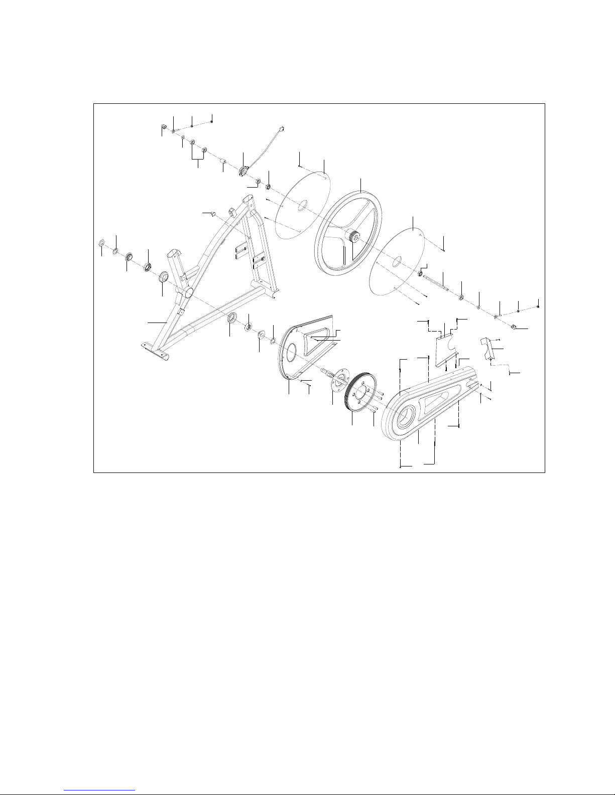
EXPLODED VIEW 1
3
EXPLODED VIEW 2
54
55
56
57
58
1
58
57
59
60
61
62
63
64
65
66
67
68
69
68
69
70
71
72
72
72
73
73
73
73
74
74
75
76
77
75
76
77
78
78
79
79
80
81
82
83
83
82
84
87
81
85
79
86

4
PARTS LIST
NO.
Description
Qty.
NO.
Description
Qty.
1
Main frame
1 40
Screw M8*16
8
2
Rear stabilizer
1 41
Arc washer d8*Φ20*R16*2
2
3
Foot pad Φ43*14*M8*25
5 42
Front post
1
4
Nut M8*H5.5*S1
5 43
Grommet
1
5
End cap PT60*30*20
4 44
Handlebar
1
6
Screw M8*40*20*S6
4 45
Spring washer d8
4
7
Washer d8*Φ16*1.5
10 46
Sensor wire 1
1
8
Front stabilizer
1 47
Round end cap Φ25*16
2
9
Nylon nut M6*H6*S10
2 48
Sensor pad
1
10
Roll wheel Φ23*32*Φ6
2 49
Foam grip Φ23*5*400
2
11
Bolt M6*48*18*S10
2 50
Computer
1
12L/R
Pedal 76X 1/2"
2 51
Wrench S6
1
13
Knob M16*1.5*22*Φ37 English
1 52
Wrench S13-14-15
1
14
Bushing PT60*30*50*20*93*15
1 53
U shape seat
1
15
Saddle post
1 54
Nut 7/8” left
1
16
Knob M10*Φ58*32
1 55
Washer
1
17
Washer d10*Φ20*2
1 56
Inside bearing collar 7/8” left
1
18
Nylon nut M8
3 57
Ball bearing
2
19
Washer d8*Φ16*1.5
3 58
Bearing housing
2
20
Square end cap J38*38*14
2 59
Bearing collar 15/16”
1
21
Saddle across tube
1 60
Washer d24*Φ40*3
1
22
Saddle
1 61
Inner chain cover
1
23
Brake handle Φ8*Φ40*195
1 62
Crank with belt wheel connection
1
24
Small cover
1 63
Belt wheel
1
25
Brake spacer Φ12*Φ9*15
1 64
Screw M10*16*S6 grade 8.8
4
26
Plastic washer Φ8.5*Φ16*2
3 65
Outer chain cover
1
27
Nut M8*H5*S12
1 66
Blanking plate
1
28
Spring Φ1*Φ11*57*N11
1 67
Front cover
1
29
Washer d6*Φ16*1.2
1 68
Screw ST4.8*13*Φ8
2
30
Nylon nut M6*H6*S10
1 69
Washer d5*Φ13*1
2
31
Bolt M6*10*S10
2 70
Washer d6*Φ16*1.5
2
32
Washer d6*Φ12*1.2
3 71
Screw M6*12*Φ12
2
33
Brake Spring pad
1 72
Screw ST4*16*Φ9
5
34
Screw M5*30*Φ8
2 73
Screw ST4.2*13*Φ8
6
35
Brake pad
1 74
Nut M10*1*H20.5*S15
2
36
Washer d5*Φ10*1
2 75
Adjusting screw M6*36*Φ10*5
2
37
Nylon nut M5
2 76
Nut M6*H5*S10
2
38
Wool felt t8*30*110
1 77
Nut M6*H6*S10
2
39
Screw M6*10*Φ10
1 78
SpacerΦ16*Φ10.2*6
2

5
NO.
Description
Qty.
NO.
Description
Qty.
79
Nut
4 84
Flywheel
1
80
Inductor
1 85
GrommetΦ12*11*Φ3
1
81
Bearing 6000-ZZ
2 86
SpacerΦ16*10.2*16
1
82
Screw ST4.8*10*Φ8
6 87
Inertial axle
Φ10*165*M10*1.0*43*33
1
83
Flywheel cover
2

6
HARDWARE PACKAGE

7
ASSEMBLY INSTRUCTIONS
STEP 1:
Fix the Front stabilizer (8) and the Rear stabilizer (2) onto the Main
frame (1) with Screws (6) and Washers (7).

8
STEP 2:
A. Push the Brake handle (23) into the Main frame (1) down slowly and
then fix it with the Screw (39) and Washer (32).
B. Lock the Pedal (12L/R) on the *left and right crank of the Main frame
(1).
★CAUTION: The left crank has reverse threading. Turn the Left pedal (12L)
counter-clockwise to tighten. The Right pedal (12R) is tightened by turning
clockwise.
Failure to follow these instructions can result in permanent damage to your bike.

9
STEP 3:
A. Fix the Saddle (22) onto the Saddle tube (21) with Washers (19) and
Nylon nuts (18).
B. Insert the Saddle post (15) into the Main frame (1), and then lock it with
the Knob (13).
C. Put the Saddle tube (21) on the Saddle post (15), and then tighten using
the Knob (16) and Washer (17).

10
STEP 4:
A. Connect the Lower sensor wire (48) with the Upper sensor wire (46),
then push the connected sensor wire back into the tube of Main frame (1).
B. Fix the Front post (42) on the Main frame (1) with Arc washers (41),
Washers (7) and Screws (40).

11
STEP 5:
A. Assemble the Handlebar (44) on the Front post (42), and fix it with
Screws (40), Spring washers (45) and Washers (7).
B. Insert the Computer (50) onto the support of the Handlebar (44) and then
connect the Sensor wire (46) to the Computer (50).
Assembly is now complete.

12
Notice:
Push down the knob to
enforce brake, and stop
the bike immediately.
Rotate the knob
clockwise to increase
the resistance. Rotate
the knob counterclockwise to decrease
the resistance.

13
USAGE AND MAINTENANCE
1. If there is no signal coming to the computer, please check if the sensor wires
(46&48) are connected correctly.
2. If the display becomes blurry, please replace the batteries to improve the
result.
3. This bike can be leveled to compensate for uneven surfaces. To level the
bike, please raise or lower the foot pads, which are located on the bottom of
the front and rear stabilizers. To raise the foot pad, screw it counterclockwise;
to lower the foot pad, screw it clockwise (See picture below). Once the
mainframe is leveled, turn the nut (4) upward and secure it tightly against the
front and rear stabilizers.
4. Before every workout, please check the pedal axle. If the pedals have
become loose, please retighten them.
5. Always make sure all hardware parts such as bolts, nuts and washers are
positioned correctly and tightly secured.
6. Always inspect the safety chain guard that protects the moving parts of the
bike to ensure their safe and good order.
7. Always inspect the seat post, seat slider, pedals and handlebar to make
sure they are in safe and stable position before using the bike.
8. It is recommended that you lubricate all moving parts on a monthly basis.
9. Do not dismount the bike until the pedals are at a complete STOP.
#4

14
EXERCISE COMPUTER
SPECIFICATIONS:
TIME -------------------------------------------------------00:00 -- 99:59 MIN: SEC
SPEED ----------------------------------------------------0.0 – 999.9 ML/H
DISTANCE -----------------------------------------------0.00 – 99.99 ML
CALORIES -----------------------------------------------0.0 – 999.9 KCAL
KEY FUNCTIONS:
MODE: Press to select function. (Time, Speed, Distance, Calories).
-Press and hold the mode button for three seconds to reset time, distance and calories.
OPERATION PROCEDURES:
1. AUTO ON/OFF:
To turn on the computer, start pedaling, or press the MODE button. After approximately 4
minutes of inactivity, computer will turn off automatically.
2. RESET:
The computer can be reset by pressing and holding the MODE button for three seconds.
Removing the batteries will also reset the computer and return all function settings to zero.
3. MODE:
To select the LOCK MODE setting, press the MODE key when the pointer on the function
you wish to select begins to blink, once locked only the selected function will be displayed.
4. FUNCTIONS:
TIME: Counts the total time of an exercise from start to finish.
SPEED: Displays the current speed being obtained.
DISTANCE: Counts the total distance of an exercise from start to finish.
CALORIES: Counts the amount of total calories burned during an exercise from start to
finish.
SCAN: Automatically displays functions in the following order shown; time, speed, distance,
calories (repeat).
BATTERY: This monitor uses two AA batteries. If the display does not work correctly, try
installing new batteries. When replacing batteries, replace both of them. Do not mix battery
types and do not mix old and new batteries. Dispose of old batteries according to your state
and local guidelines.
 Loading...