

Page 1
1
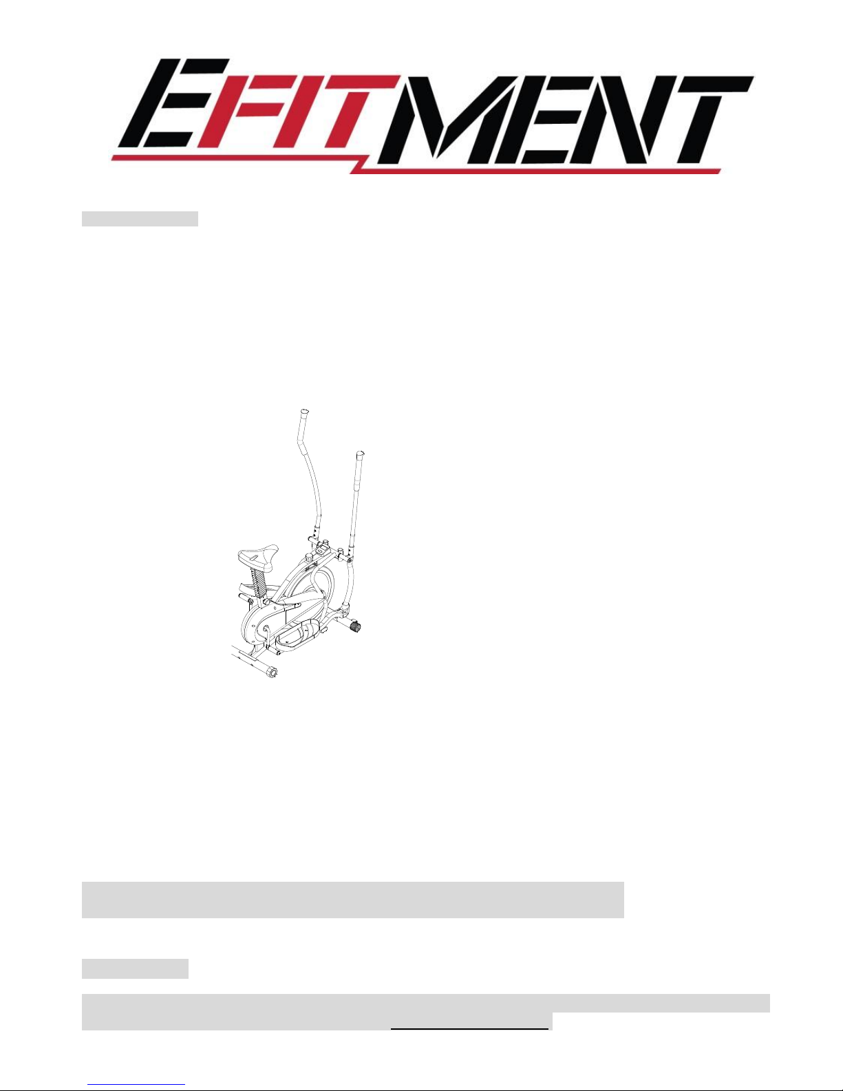
E018 Flywheel Elliptical User Manual
IMPORTANT:
Read all instructions carefully before using this product. Retain this manual for future
reference. For customer service, contact: [email protected].
Page 2

2
Page 3

3
IMPORTANT SAFETY INSTRUCTIONS
Note the following precautions before assembling and using the machine.
1.
Assemble the machine exactly as described in the instruction manual.
2.
Before exercise, in order to avoid injuring the muscle, warm-up exercises are
recommended.
3.
Please make sure all parts are not damaged and fixed well before use. This
equipment should be placed on a flat surface. Using a mat or other covering
material on the ground is recommended.
4.
Please wear proper clothes and shoes when using this equipment; do not wear clothes
that might catch any part of the equipment.
5.
Do not attempt any maintenance or adjustments other than those described in this
manual. Should any problems arise, discontinue use.
6.
Do not use the equipment outdoors. It is not a commercial model.
7.
This equipment is for household use only.
8.
This machine can be used by one person at a time.
9.
If you feel any chest pains, nausea, dizziness, or short of breath, you should stop
exercising immediately and consult your physician before continuing.
10.
This elliptical is intended for adult use only. Keep children away from the elliptical.
11.
Before beginning exercise, remove all objects within a radius of 4 feet from the machine.
12.
The maximum weight capacity for this product is 240 LBS.
WARNING: Your health can be affected by incorrect or excessive exercise. Consult a doctor
before beginning your exercise program. This machine is not suitable for therapeutic purpose.
CAUTION: Read all instructions carefully before operating this product. Retain
this Owner’s Manual for future reference.
WARNING: This product can expose you to one or more chemicals known to the
State of California to cause cancer and birth defects or reproductive harm. For
more information go to www.P65Warnings.ca.gov.
Page 4
4
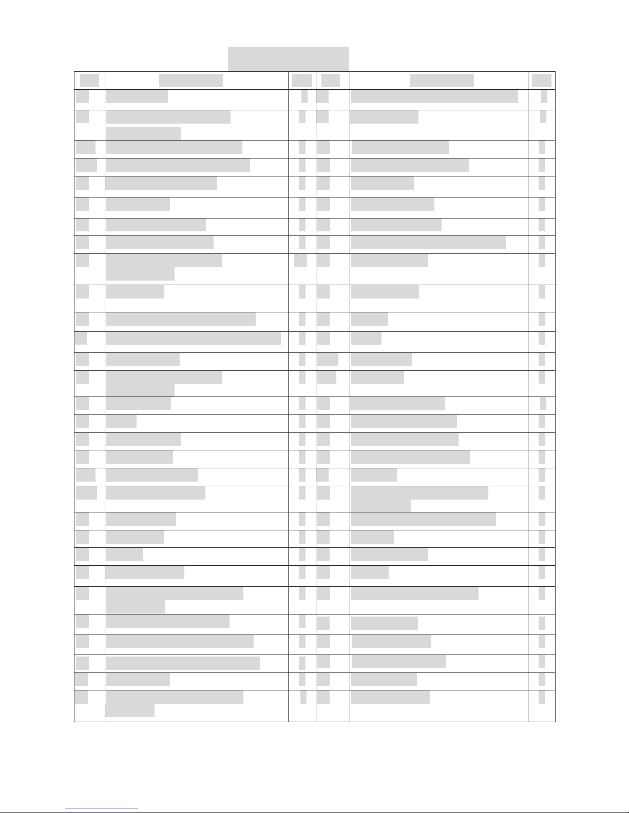
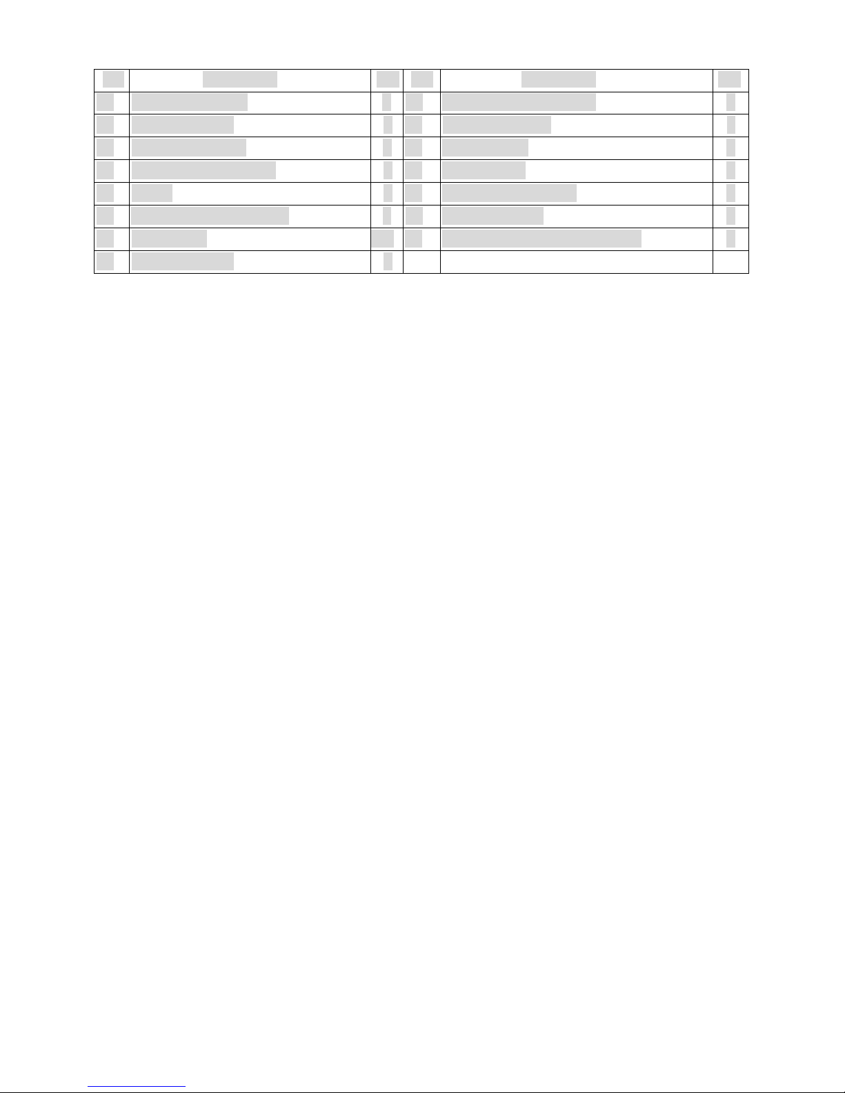
PARTS LIST
No.
Description
Qty
No.
Description
Qty
01
Main Frame
1
29
Handrail Arm End Cap Ø25x1.5
2
02
Handrail Arm Foam Grip
Ø24xØ35x280
2
30
Cap Nut M10
4
03L
Left Handrail Arm Ø25x1.8
1
31
Curve Washer Ø10
4
03R
Right Handrail Arm Ø25x1.8
1
32
Bearing Cup Ø55.6x16
2
04
Handrail Arm End cap
2
33
Bearing 7/8”
1
05
Bolt M10x20
2
34
Washer Ø35 x 2
1
06
Spring Washer Ø10
2
35
Hexagon Nut 7/8”
1
07
Washer Ø28xØ16xt5
2
36
Front Stabilizer Ø50x1.35x470
1
08
Powder Metal Bushing
Ø28xØ16x16
10
37
Nylon Nut M10
2
09
Bolt M8x40
4
38
Nylon nut M6
2
10
Front Stabilizer End Cap Ø50
2
39
Nut M6
1
11
Left/Right Foot Pedal 345x146x40
2
40
Chain
1
12
Right Handrail
1
41R
Right Cover
1
13
Powder Metal Bushing
Ø18xØ10x10
4
41L
Left Cover
1
14
Bolt M10x55
2
42
Flange Nut M10x1
2
15
Roller
2
43
Hexagon Nut M10x1
1
16
Right Foot Bar
1
44
Spring Knob M6x112
1
17
Sensor Base
1
45
Flywheel Axle Ø10x150
1
18L
Bolt for left Crank
1
46
Flywheel
1
18R
Bolt for right Crank
1
47
Phillips Self Tapping Screw
ST 4.2 x 12
1
19
Nylon Nut M8
4
48
Wave Washer Ø26xØ16x0.3
4
20
Bolt M8x50
4
49
Console
1
21
Sensor
1
50
Eyebolt M6x36
2
22
Plastic Bushing
2
51
Nut M6
2
23
Phillips Self Tapping Screw
ST 4.0 x 40
4
52
Rotation Rod Ø15.8x376
1
24
Chain Pulley with Crank
1
53
Left Foot Bar
1
25
Rear Stabilizer End Cap Ø50
2
54
End Cap 60x30
2
26
Rear Stabilizer Ø50x1.35x500
1
55
Spring Washer Ø6
2
27
Bolt M10x56
4
56
Left Handrail
1
28
Phillips Self Tapping Screw
ST4.2x25
3
57
Left Nylon Nut
1
Page 5
5
No.
Description
Qty
No.
Description
Qty
58
Right Nylon Nut
1
66
Washer Ø10xØ20x2.0
1
59
Bearing 15/16”
1
67
Tension Bracket
2
60
Washer Ø40x2.8
1
68
Bolt M6 x 45
2
61
Hexagon Bolt M6x35
1
69
Cap Nut M8
4
62
Brake
1
70
Spring Washer Ø12
2
63
Spacer Bushing Ø10x9
1
71
Wire Plug Ø12
1
64
Nut M10x5
2
72
Curve Washer Ø8xØ16xδ1.5
4
65
Bearing 6000Z
2
Page 6

6
HARDWARE BAG
Page 7

7
EXPLODED DRAWING
Page 8
8
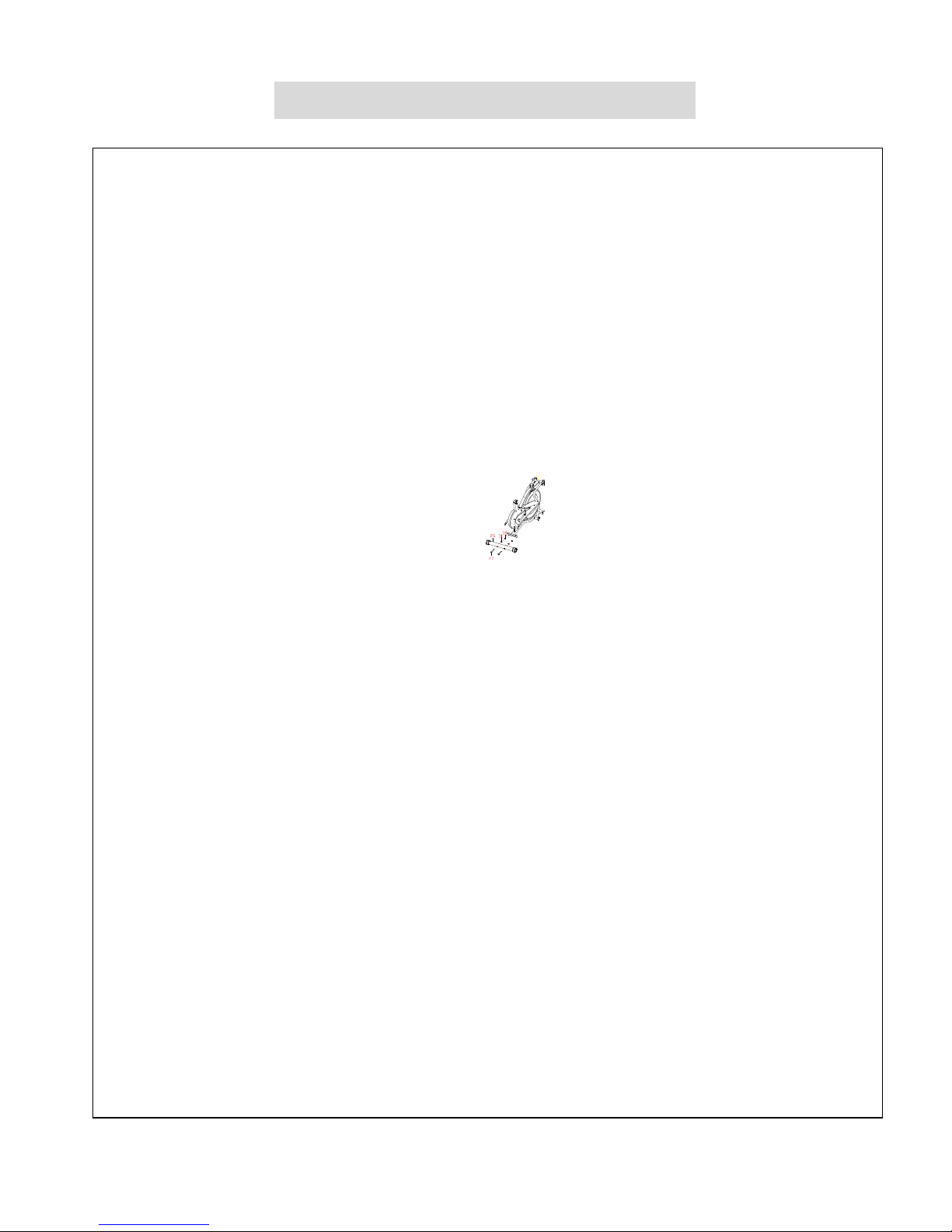
ASSEMBLY INSTRUCTIONS
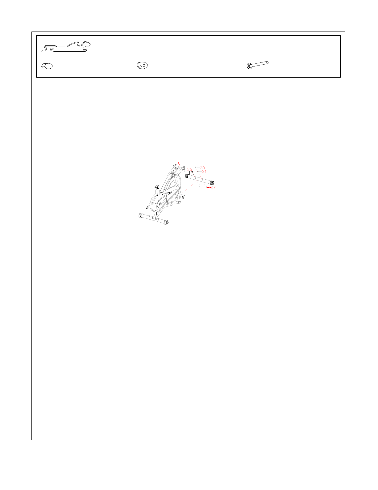
Spanner S10-S13-S17-S19
(30) Cap Nut M10, 2PCS
(31) Curve Washer M10x56, 2PCS
(27) Bolt Ø10, 2PCS
STEP 1:
Attach the Rear Stabilizer (No. 26) onto the Main Frame (No. 1) with 2 Cap Nuts (No. 30), 2
Curve Washers (No. 31) and 2 Bolts (No. 27). Tighten with the Spanner provided.
Page 9
9
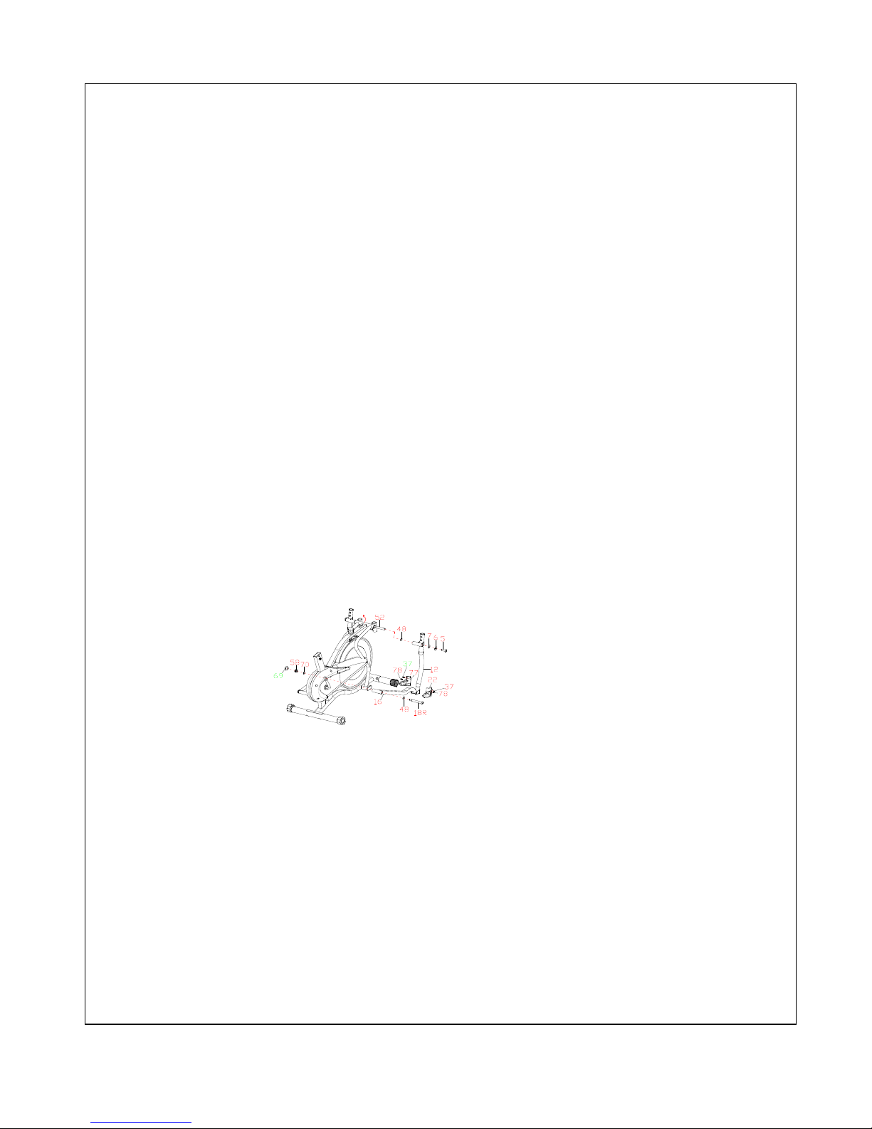
Spanner S10-S13-S17-S19
(30) Cap Nut M10, 2PCS
(31) Curve Washer M10x56, 2PCS
(27) Bolt Ø10, 2PCS
STEP 2:
Attach the Front Stabilizer (No. 36) onto the Main Frame (No. 1) using 2 Cap Nuts (No. 30), 2
Curve Washers (No. 31) and 2 Bolts (No. 27). Tighten with the Spanner provided.
Page 10
10
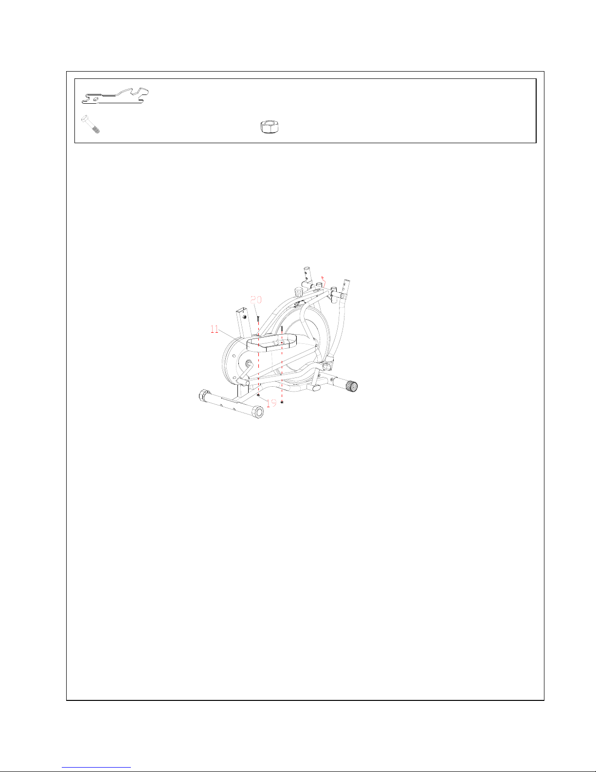
Allen Wrench S8
Allen Wrenches S6
Spanner S10-S13-S17-S19
(5) Bolt M10x20, 2PCS (6) Spring Washer Ø10, 2PCS
(7) Washer Ø28xØ16xt5, 2PCS
(48) Wave Washer Ø26xØ16x0.3, 2PCS
(52) Rotation Rod, 1PC
(18R) Bolt for right Crank, 1PC (18L) Bolt for left Crank, 1PC
(48) Wave Washer Ø26xØ16x0.3, 1 PC (48) Wave Washer Ø26xØ16x0.3, 1 PC
(70) Spring Washer Ø12, 1 PC (70) Spring Washer Ø12, 1 PC
(58) Nylon Nut for right Crank, 1PC (57) Nylon Nut for left Crank, 1PC
Page 11

11
STEP 3:
Remove 2 Bolts (No. 5), 2 Spring Washers (No. 6), 2 Washers (No. 7), and 2 Wave Washers
(No. 48) from the Rotation Rod (No. 52).
Insert the Rotation Ro d (No. 52) into the hole of the Main Frame (No. 1). Attach the L & R
Handrails (No. 56 & 12) onto the Rotation Rod (No. 52) using 2 Bolts (No. 5), 2 Spring
Washers (No. 6), 2 Washers (No. 7) and 2 Wave Washers (No. 48). Tighten with Allen
Wrench provided.
NOTE: Bolts (No. 18 L/R) for right Crank and left Crank are marked “R” for Right and “L” for
Left.
Attach the Right Foot Bar (No. 16) onto the right Crank using Bolt for Right Crank (No.
18R), Wave Washer (No. 48), Spring Washer (No. 70), and Right Nylon Nut (No. 58). Tighten
the Right Bolt (No.18R) clockwise and tighten the Right Nylon Nut (No. 58) counterclockwise
with Allen Wrench and Spanner provided.
Repeat the same procedure to attach the Left Foot Bar (No. 53) onto the left Crank, tighten the
Left Bolt (No. 18L) counter-clockwise and tighten the Left Nylon Nut (No. 57) clockwise.
Page 12
12
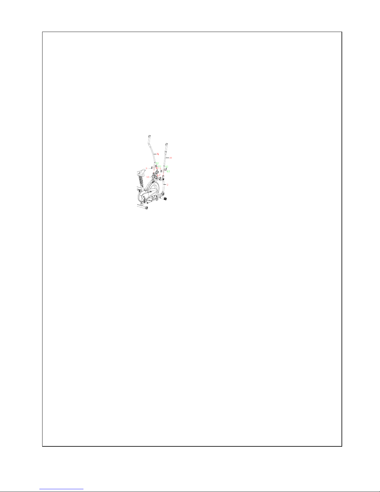
STEP 4:
Attach the Right Foot Pedal (No.11) onto the Right Foot Bar (No.16) using 2 Bolts (No.20)
and Nylon Nuts (No.19). Tighten with the Spanner provided.
Repeat the same procedure to assemble Left Foot Pedal (No.11) onto the Left Foot Bar
(No.53).
Spanner S10-S13-S17-S19
(20) Bolt M8x50, 4PCS (19) Nylon Nut M8, 4PCS
Page 13
13
Spanner with Phillips Screwdriver S1-S14-S15
Allen Wrenches S6
(69) Cap Nut M8, 4PCS
(72) Arc Washer Ø8xØ16xδ1.5, 4PCS
(9) Bolt M8x40, 4PCS
STEP 5:
Right Handrail (No. 12) using 2 Bolts (No. 9), 2 Curve Washers (No. 72) and 2 Cap Nuts
(No. 69). Tighten nuts with Allen Wrenches S6 and the Spanner with Phillips Screwdriver
provided.
Repeat the same procedure to assemble the Left Handrail Arm (No. 3L).
Connect the Sensor Wire (No. 21) with the wire of Console (No. 49). Fix the Console
(No. 49) to the plate on the Main Frame (No. 1).
Page 14
14
ADJUSTMENTS
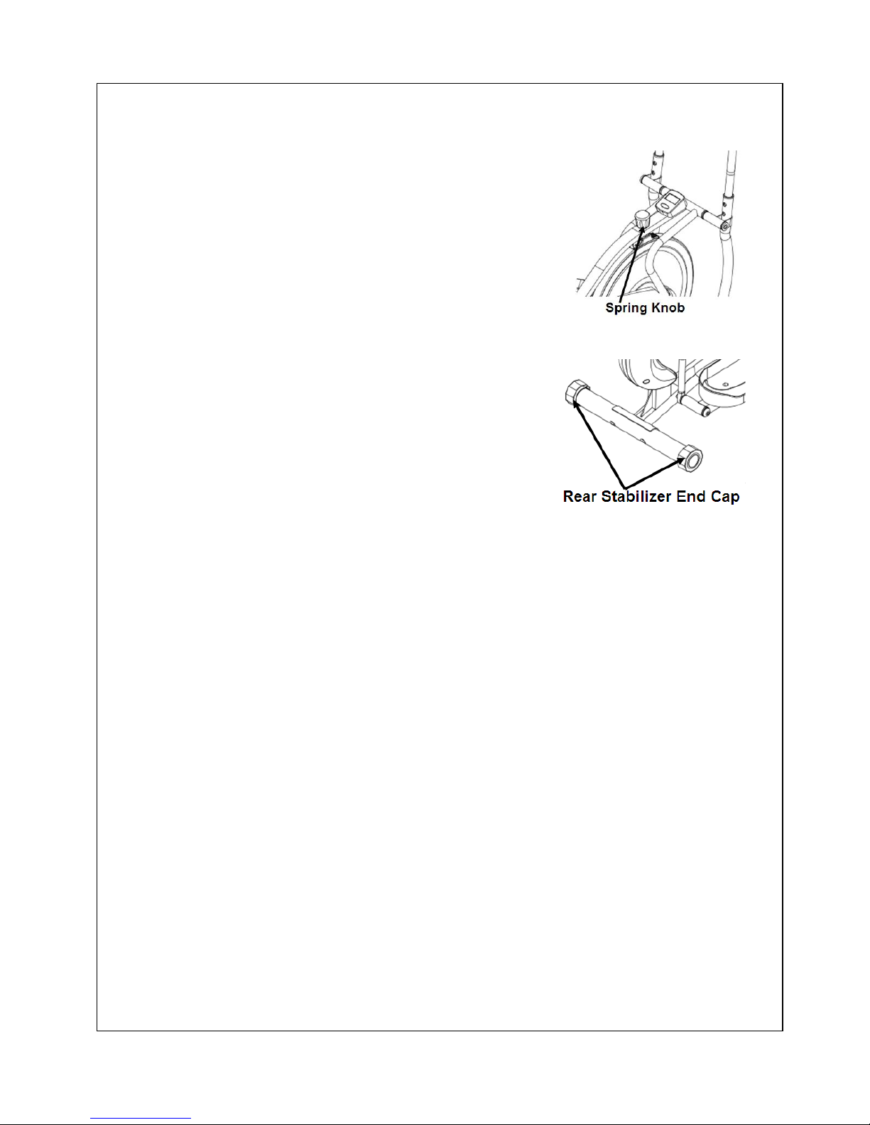
Adjusting the Spring Knob
To increase the tension, turn the Spring Knob clockwise.
To decrease the tension, turn the Spring Knob
counter-clockwise.
Adjusting the Rear Stabilizer End Cap
Turn the Rear Stabilizer End Cap as needed
to level the elliptical.
MAINTENANCE
Cleaning
The elliptical bike can be cleaned with a soft clean damp cloth. Do not use abrasives or
solvents on plastic parts. Please wipe your perspiration off the elliptical bike after each use.
Be careful not get excessive moisture on the computer display panel as this might cause an
electrical hazard or electronics to fail.
Please keep the elliptical bike, especially the computer console out of direct sunlight to
prevent screen damage.
Before use and every week, please inspect all assembly bolts and pedals on the
machine to make sure they are tightened properly.
Storage
Store the elliptical bike in a clean and dry environment away from children.
Page 15
15
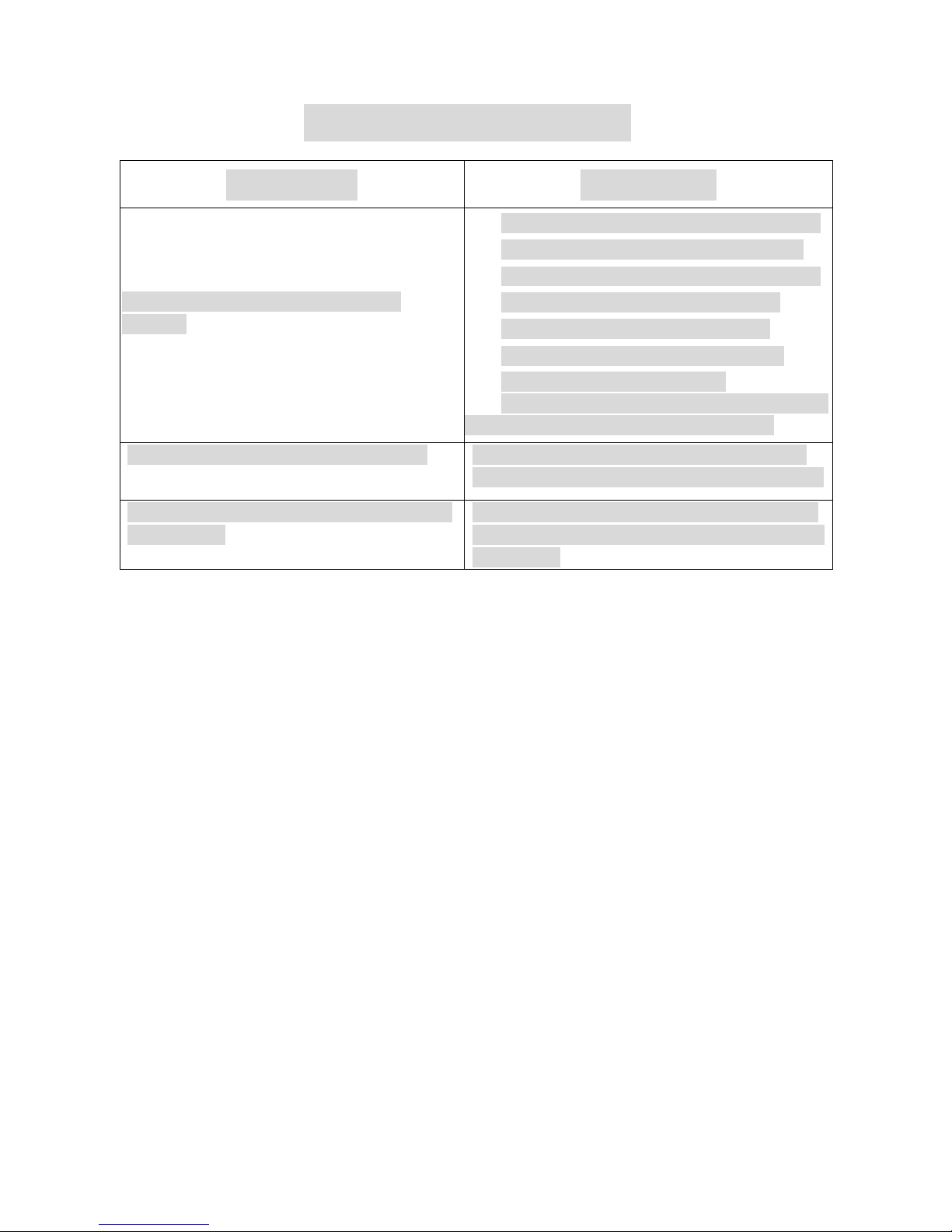
TROUBLESHOOTING
PROBLEM
SOLUTION
There is no display on the computer
console.
1. Remove the computer console and verify
the wire that comes from the computer
console is properly connected to the wire
that comes from the handlebar post.
2. Check if the batteries are correctly
positioned and battery springs are in
proper contact with batteries.
3. The batteries in the computer console may
be dead. Change to new batteries.
The elliptical bike wobbles when in use
Turn the rear stabilizer end cap on the rear
stabilizer as needed to level the elliptical bike.
The elliptical bike makes squeaking noise
when in use.
The bolts may be loose on the elliptical bike.
Please inspect all of the bolts and tighten any
loose bolts.
Page 16
16
EXERCISE COMPUTER
FUNCTIONS:
TIME………………………………00:00~99:59 MIN/SEC
SPEED……………………………0.0~99.9 ML/H
DISTANCE……………………… 0.00~999.9 ML
CALORIE…………………………0.0~9999 CAL
OPERATION PROCEDURES:
1. AUTO ON/OFF
The exercise computer turns on when any key is pressed or when it receives an input from
the speed sensor.
The exercise computer turns off automatically when the speed sensor has no signal input
and no key is pressed for approximately 4 minutes.
2. RESET
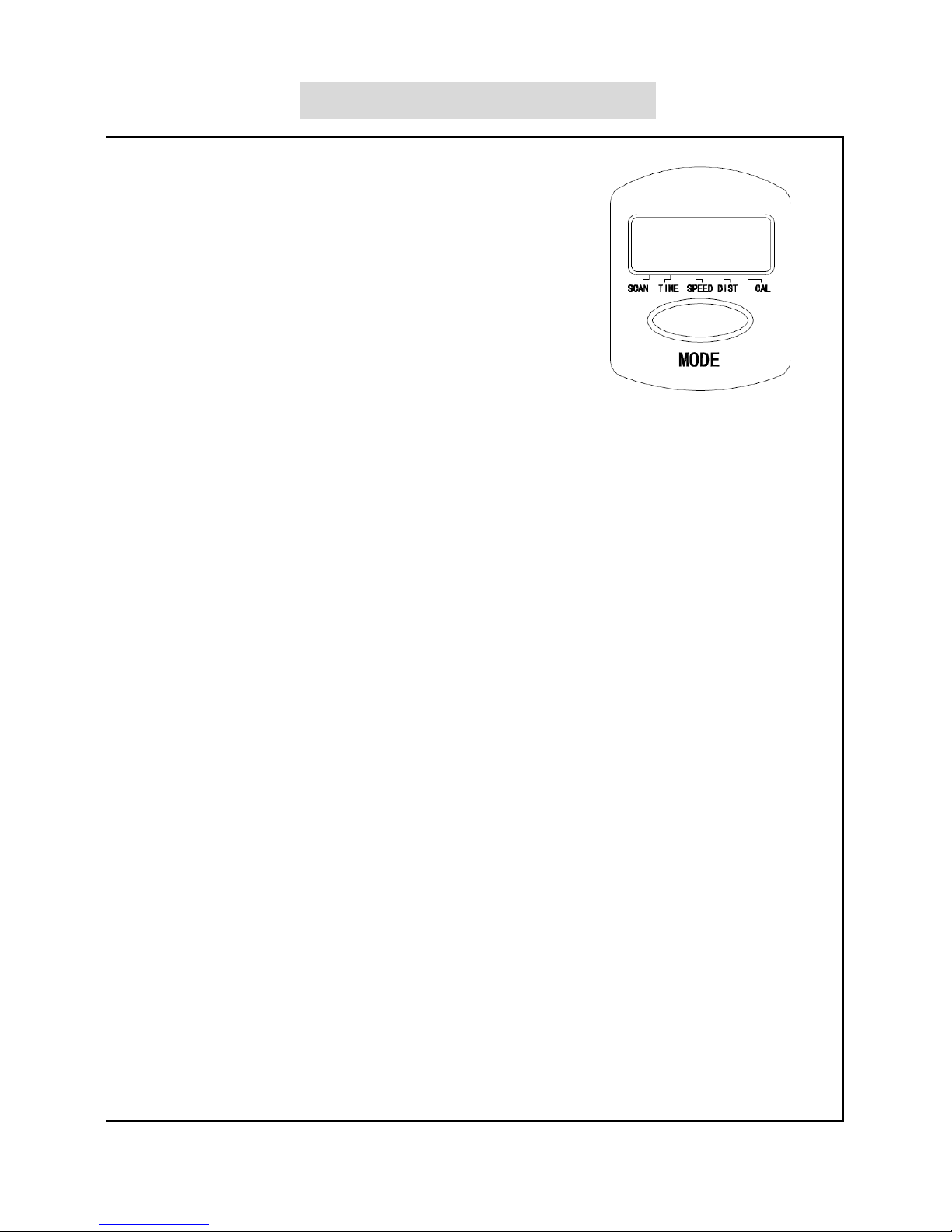
The exercise computer can be reset any time by pressing the MODE key for 3 seconds or by
replacing the battery.
3. FUNCTION SELECTION
Press the MODE key to select any function and lock on to a particular function you want.
4. SCAN FUNCTION
Press MODE until pointer points to SCAN.
Automatic rotates displays the following functions in the order shown:
TIME-SPEED-DISTANCE- CALORIE
BATTERIES
The exercise computer uses one AAA battery. If there is a problem with the display try
changing the battery first. Dispose of old battery according to your regional guidelines.
Version 1.1
 Loading...