

Page 1
E005 MAGNETIC ELLIPTICAL BIKE
USER MANUAL
IMPORTANT! Read all instructions carefully before using this product. Save this user manual
for future reference. For customer service, contact: [email protected]
Page 2

IMPORTANT SAFETY NOTICE
Note the following precautions before assembling and using the machine.
1. Assemble the machine exactly as described in the instruction manual.
2. Check all the bolts, nuts and other connections before using the machine for the first time to
ensure the machine is in the safe condition.
3. Set up the machine in a dry level place and keep it away from moisture and water.
4. Place a suitable base (e.g. rubber mat, wooden board etc.) beneath the machine in the
assembly area to avoid dirt.
5. Before beginning exercise, remove all objects within a radius of 4 feet from the machine.
6. Only use the supplied tools or suitable tools of your own to assemble or repair the machine.
7. Your health can be affected by incorrect or excessive exercise. Consult a doctor before
beginning your exercise program. This machine is not suitable for therapeutic purpose.
8. Only use the elliptical when it is working correctly. Use only original spare parts for any
necessary repairs.
9. This machine can be used by one person at a time.
10. Wear clothes and shoes that are suitable for fitness training with the machine. Do not wear
clothing that could get tangled in the machine.
11. If you have a feeling of dizziness, sickness or other abnormal symptoms, please stop training
and consult a doctor immediately.
12. This elliptical is intended for adult use only. Keep children away from the elliptical.
13. Do not put fingers or objects in the moving parts of the machine.
14. Remove drops of sweat from the machine immediately after finishing training. Do not use
aggressive cleaning articles to clean the machine.
15. Maximum user’s weight is 220 LBS.
CAUTION: Your bike was not designed for reverse pedaling. Reverse pedaling will damage the
bike.
WARNING: This product can expose you to one or more chemicals known to the
State of California to cause cancer and birth defects or reproductive harm. For
more information go to www.P65Warnings.ca.gov.
1
Page 3
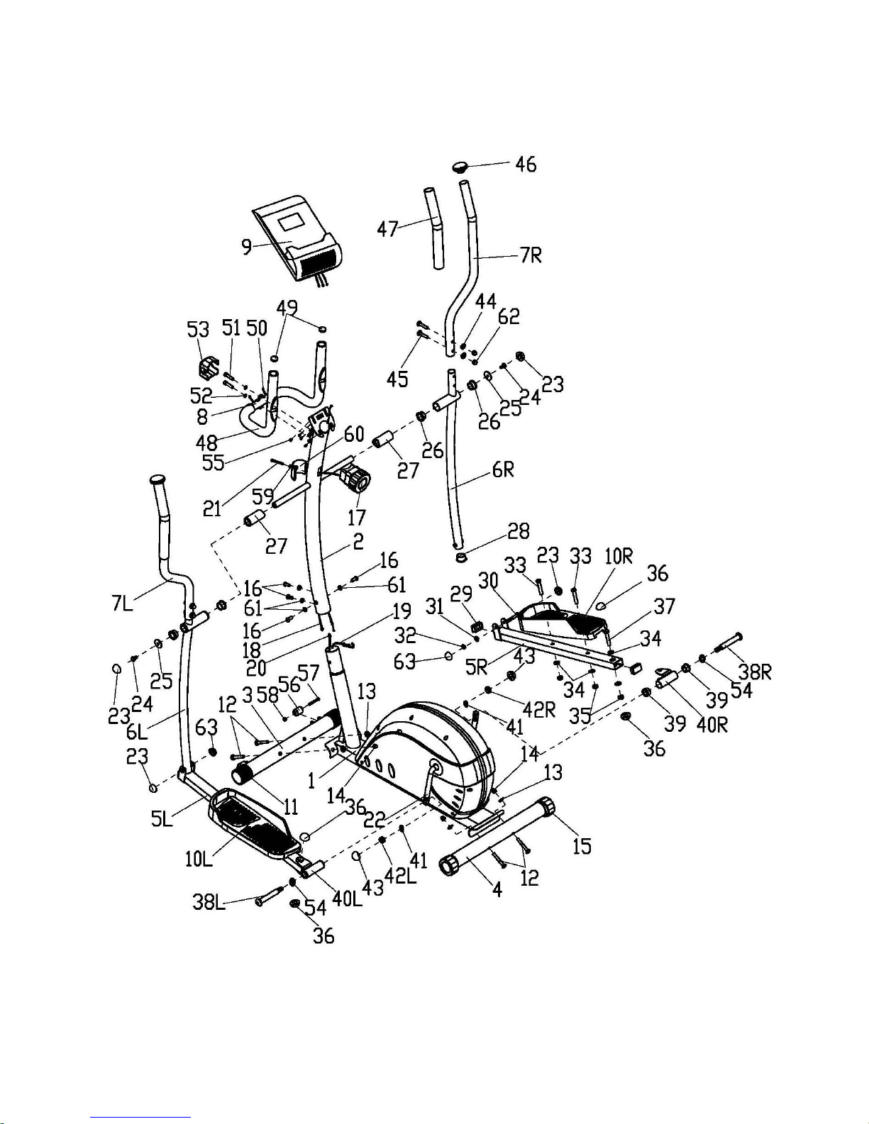
EXPLODED DIAGRAM
2
Page 4

PARTS LIST
NO.
DESCRIPTION
QTY
NO.
DESCRIPTION
QTY
1
Main frame
1
33
Hex bolt
4 2 Handlebar post
1
34
Flat washer
8
3
Front stabilizer
1
35
Nylon nut
6
4
Rear stabilizer
1
36
Cap S17
4
5L/R
Pedal tube
1/1
37
Hex bolt
2
6L/R
Handrail arm
1/1
38L/R
Pedal bolt
1/1
7L/R
Handlebar
1/1
39
Powder metal bushing 2
4
8
Stationary Handlebar
1
40L/R
Pedal tube link
1/1
9
Computer
1
41
Spring washer
2
10L/R
Pedal
1/1
42L/R
Nylon nut
1/1
11
Front stabilizer end cap
2
43
Cap S19
2
12
Carriage bolt
4
44
Curve washer
4
13
Curve washer
4
45
Carriage bolt
4
14
Cap nut
4
46
Handlebar end cap
2
15
Rear stabilizer end cap
2
47
Handlebar foam grip
2
16
Bolt
4
48
Stationary handlebar foam
grip
2
17
Tension controller
1
49
Stationary handlebar end
cap
2
18
Connection wire
1
50
Pulse wire
2
19
Tension cable
1
51
Bolt
2
20
Sensor wire
1
52
Spring washer
2
21
Screw
1
53
Handlebar clamp cover
1
22
Crank
1
54
Wave washer
2
23
Cap S14
4
55
Screw
4
24
Hex bolt
2
56
Roller
2
25
Flat washer
2
57
Hex screw
2
26
Powder metal bushing 1
4
58
Nylon nut
2
27
Spacer
2
59
Flat washer
1
28
Round cap
2
60
Tension cover
1
29
Square cap
4
61
Wave washer
4
30
Outer hex bolt
2
62
Cap nut
4
31
Flat washer
2
63
Cap S13
2
32
Nylon nut
3
3
Page 5
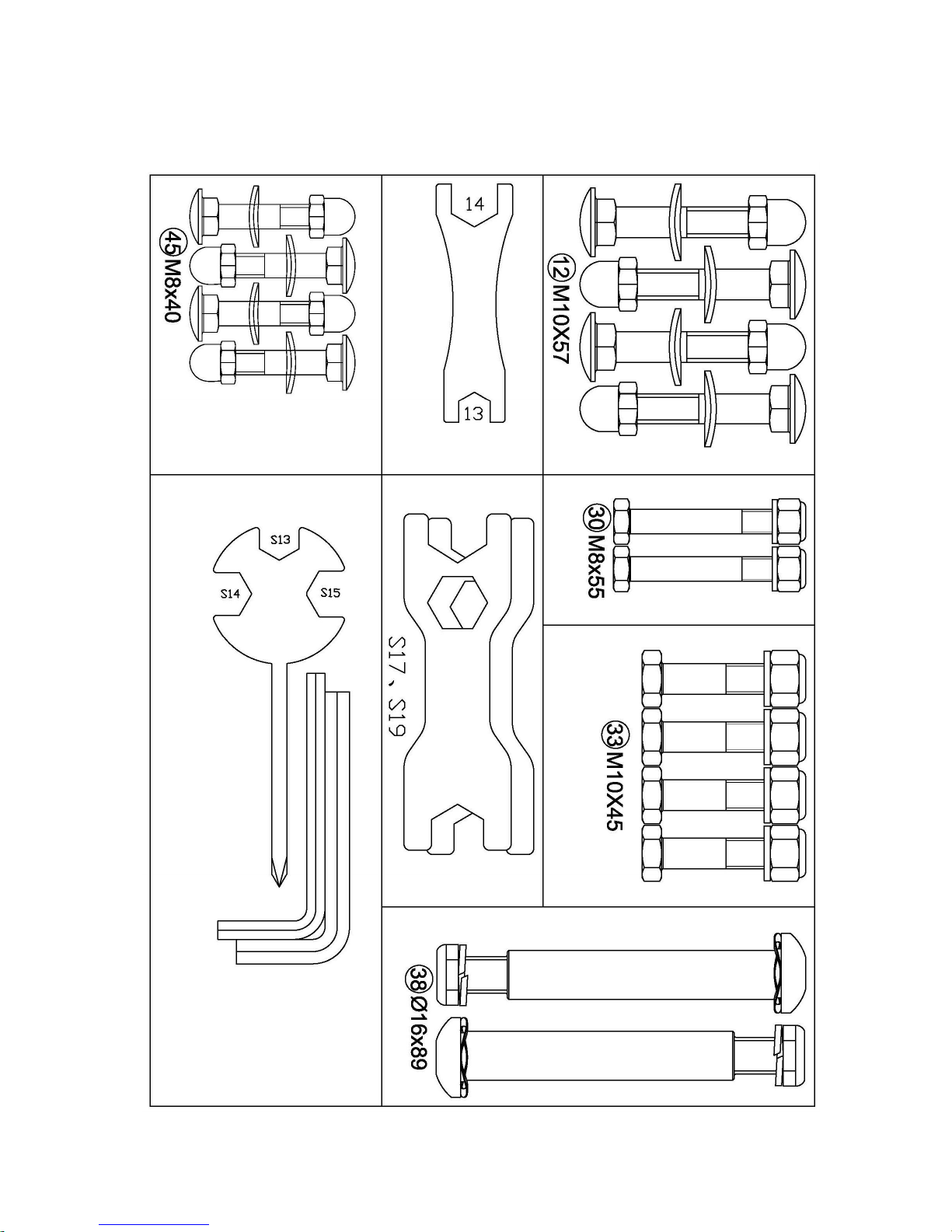
HARDWARE PACKAGE
4
Page 6
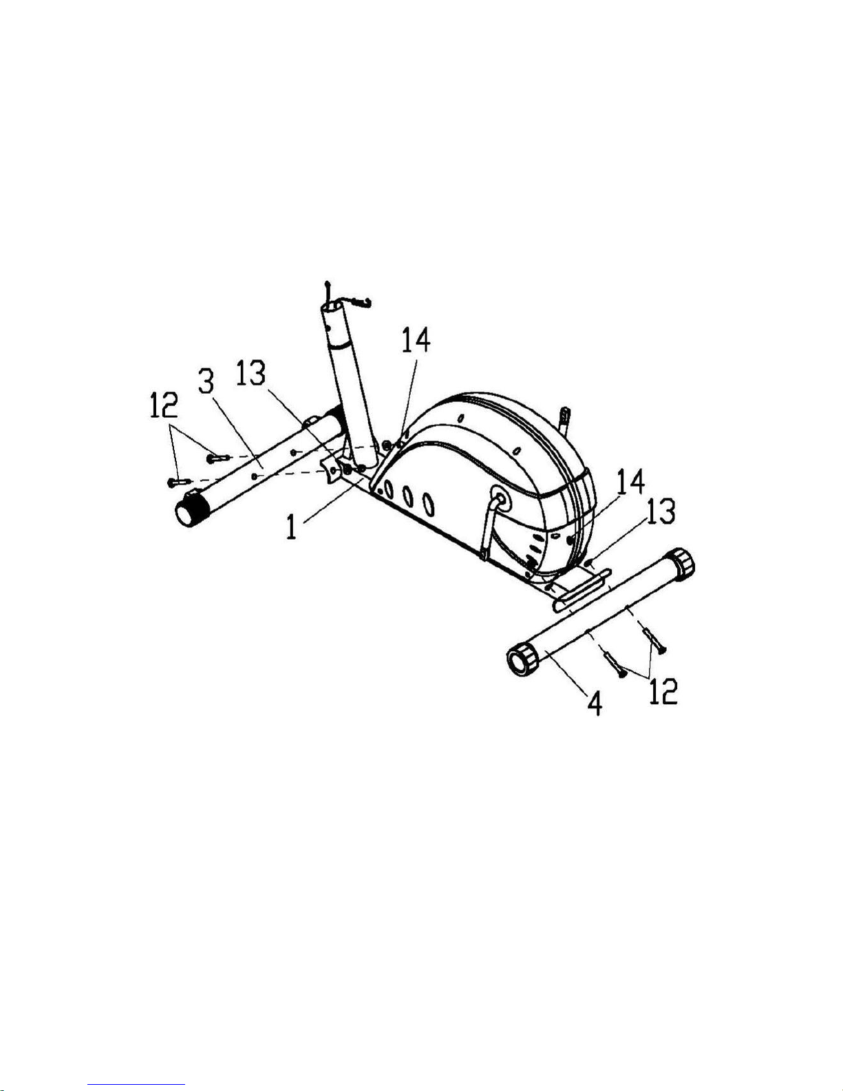
ASSEMBLY INSTRUCTIONS
STEP 1.
Attach the Front and Rear Stabilizers (3, 4) onto the curve plates of Main Frame (1) with the
Carriage Bolts (12), Curve Washers (13), and Cap Nuts (14).
5
Page 7
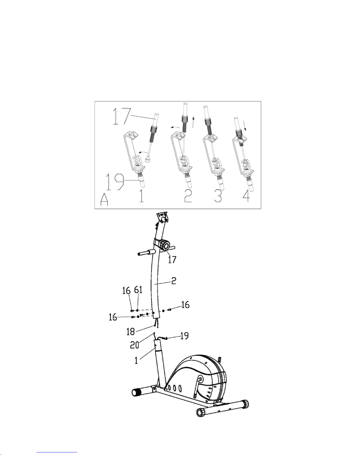
STEP 2.
1. Check the Tension Controller (17) is at Level 1 (lowest resistance) to ensure the cable is the
longest. Put the cable end of resistance cable of Tension Controller (17) into the spring hook
of Tension Cable (19). Pull the resistance cable of Tension Controller (17) up and force it
into the gap of metal bracket of Tension Cable (19) as shown in the drawing of figure.
2. Connect the Sensor Wire (20) from Main Frame (1) to the Connection Wire (18) from
Handlebar Post (2).
3. Insert the Handlebar Post (2) into the tube of the Main Frame (1) and secure with four Curve
Washers (61) and Bolts (16) that were removed.
6
Page 8
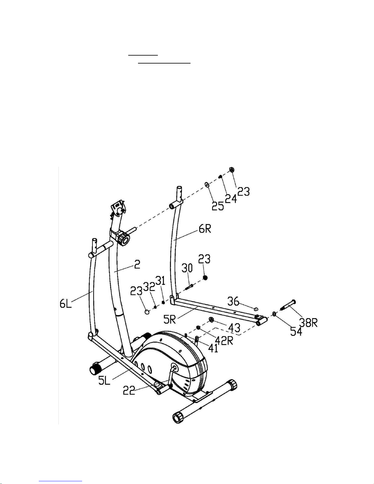
STEP 3.
NOTE: The Right and Left Pedal Bolts (38R/L) are marked with “R” & “L”. The Right Pedal
Bolt (38R) should be turned clockwise to tighten. The Left Pedal Bolt (38L) has reverse
threading and should be turned counterclockwise to tighten. In order to install the Right and Left
pedal bolts (38R/L) easily, you can move the Crank (22) in order to choose a good location for
inserting the Right and Left Pedal Bolts (38R/L)
1. Insert the Handrail Arm (6L/R) onto the handlebar shaft of the Handlebar Post (2), secured
with the Hex Bolt (24) and Flat Washer (25). Don’t tighten yet.
2. Attach the Pedal Tube (5L/R) to the Crank (22) with the Pedal Bolt (38L/R), Wave Washer
(54), Spring Washer (41) and Pedal Nylon Nut (42L/R).Don’t tighten yet.
3. Attach the Handrail Arm (6L/R) to Pedal Tube (5L/R) with Outer Hex Bolt (30), Flat
Washer (31), Nylon Nut (32). Now tighten the Hex Bolt (24) and Pedal Nylon Nut (42L/R),
and put on the Caps (43),(23),(63),(36).
7
Page 9
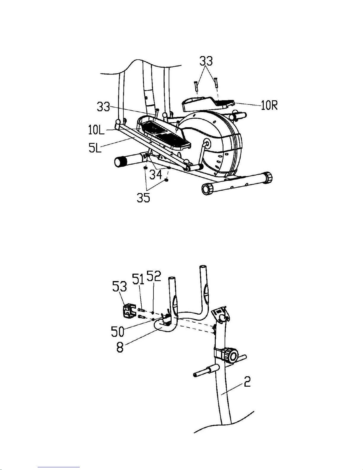
STEP 4.
Attach the Pedal (10L/R) to the Pedal Tube (5L/R) with Hex Bolt (33), Flat Washer (34) and
Nylon Nut (35).
STEP 5.
Thread the Pulse Wire (50) from the hole of handlebar clamp and guide it out of the computer
bracket. Attach the Stationary Handlebar (8) onto the Handlebar Post (2) with Bolts (51) and
Spring Washers (52). And then put on the Handlebar Clamp Cover (53).
8
Page 10
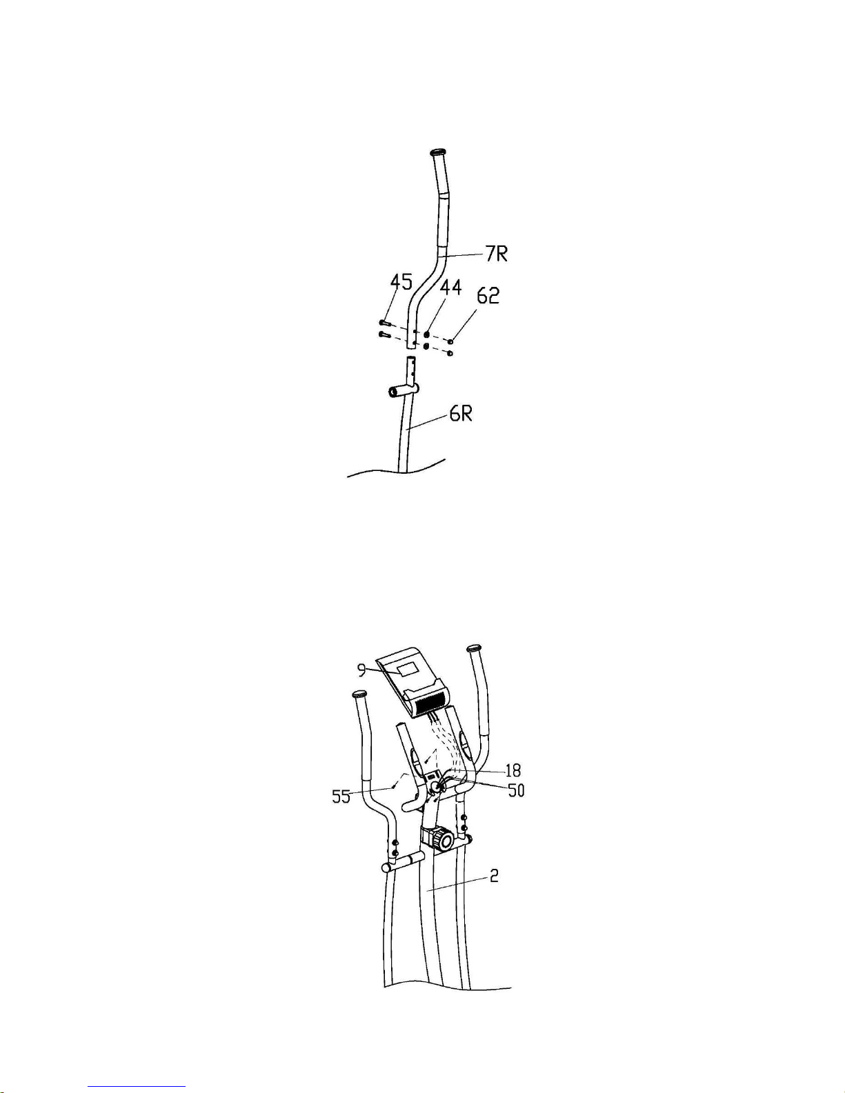
STEP 6.
Insert the Right Handlebar (7R) onto the Right Handrail Arm (6R). Secure with the Carriage
Bolts (45), Curve Washers (44) and Cap Nuts (14). Then attach the Left Handlebar (7L) to the
Left Handrail Arm (6L) in the same way.
STEP 7.
Open the battery cover and install two batteries into the battery compartment on the back of
Computer (9). Remove two Screws (55) and Flat Washers (54) from back of the Computer (9).
Connect the Sensor Wire (18) and Pulse Wires (50) with the wires of the Computer (9). Attach
the Computer (9) onto the top plate of the Handlebar Post (2) with two Screws (55) and Flat
Washers (54) that were removed.
Assembly is now complete!
9
Page 11
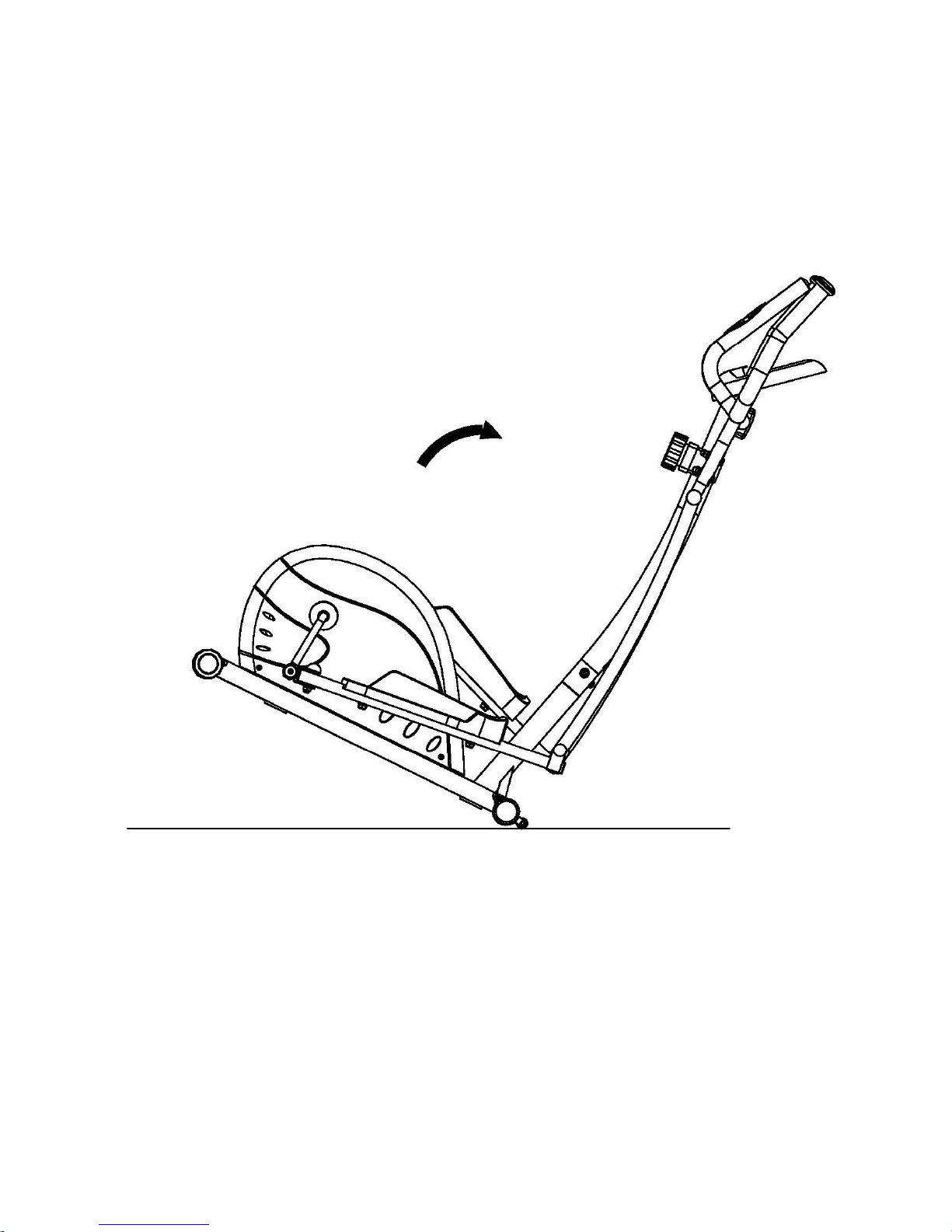
Moving the Bike
To move the elliptical, hold by the handles of the Stationary Handlebar (8). Tilt the elliptical until
the wheels of the Front Stabilizer (3) touch the floor. Then you can wheel the elliptical to the
desired location.
10
Page 12
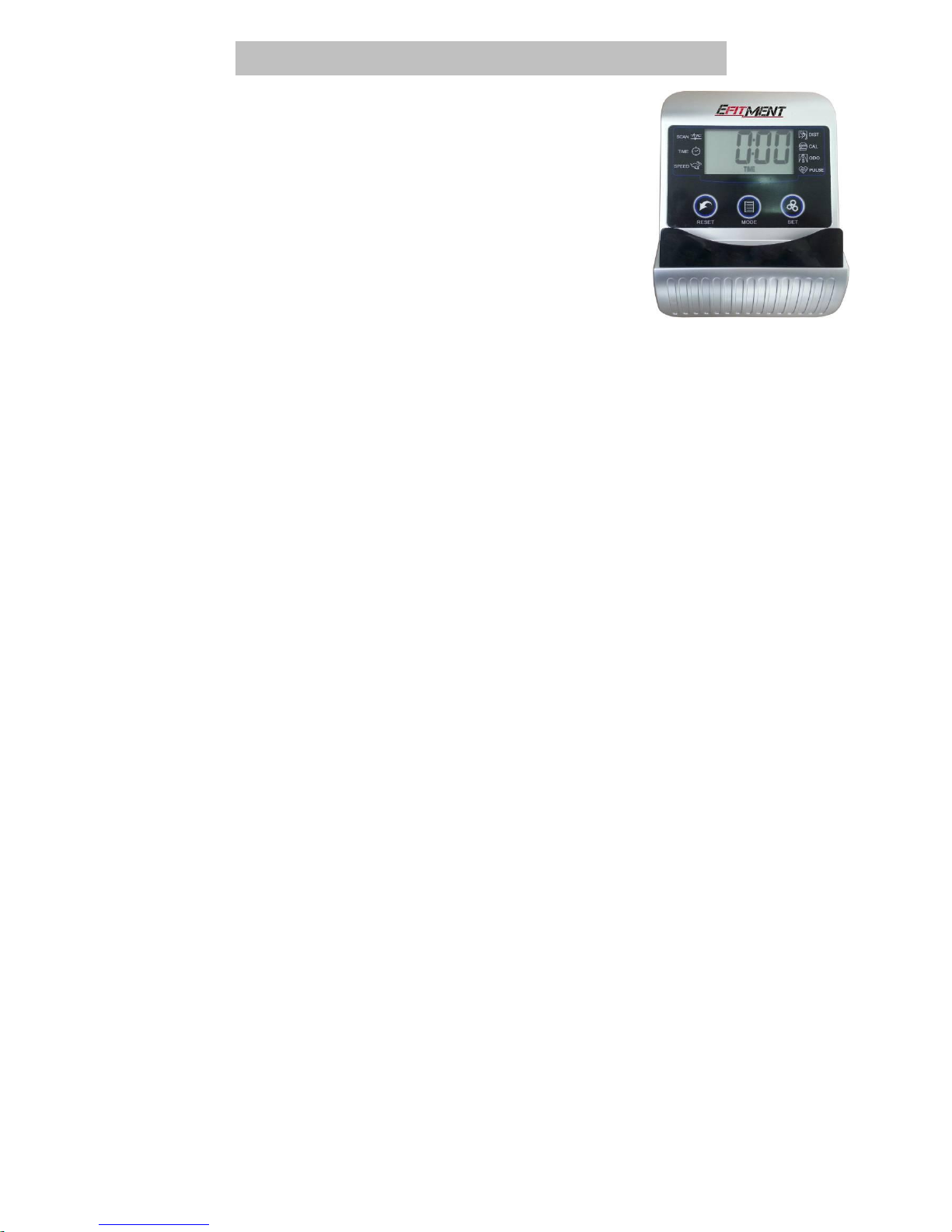
EXERCISE COMPUTER INSTRUCTIONS
SPECIFICATIONS:
TIME……………………………………………………….00:00-99:59
SPEED(SPD)..………………………………………… 0.0-99.9ML/H
DISTANCE(DIST)………………………………………0.00-999.9ML
CALORIE(CAL)…………………………………………0.00-9999KCAL
ODOMETER(ODO)…………………………..………0.0-9999ML
PULSE (PUL) ……...................................................0,40~240BPM
KEY FUNCTIONS:
MODE: Press to select a function
SET: Press to preset value for “TIME”, “DISTANCE”, “CALORIES”, or “PULSE”.
CLEAR(RESET): Press to clear the value
OPERATION PROCEDURES:
1. AUTO ON/OFF
To turn on the meter, start pedaling or press any key.
After approximately 4 minutes of inactivity, the monitor will turn off.
2. RESET
The unit can be reset by either changing battery or pressing and holding the MODE key for 3
seconds.
FUNCTIONS:
1. TIME: The total working time will be shown when starting exercise.
2.SPEED: The current speed will be shown.
3.DISTANCE: The distance of each workout will be displayed.
4.CALORIE: The calorie burned will be displayed when starting exercise.
5.ODOMETER: The total accumulated distance will be shown.
6.PULSE: Press the MODE key until the pointer advance to PULSE . Place the palms of your
hands on both of the contact pads(or put ear-clip to ear),and wait for 30 seconds for the most
accurate reading. User’s current heart rate will be displayed in beats per minute.
SCAN: Continuously displays each function in sequence for 4 seconds at a time.
COUNTDOWN FUNCTION
You can preset values to countdown TIME, CALORIES or DISTANCE. Press MODE until the
function you want is displayed. Make sure meter is not in SCAN. Press SET to increase the value.
Start pedaling and the meter will countdown.
BATTERY: If there is a problem with the display, try changing the batteries first.
11
Version 1.1
 Loading...