

Page 1
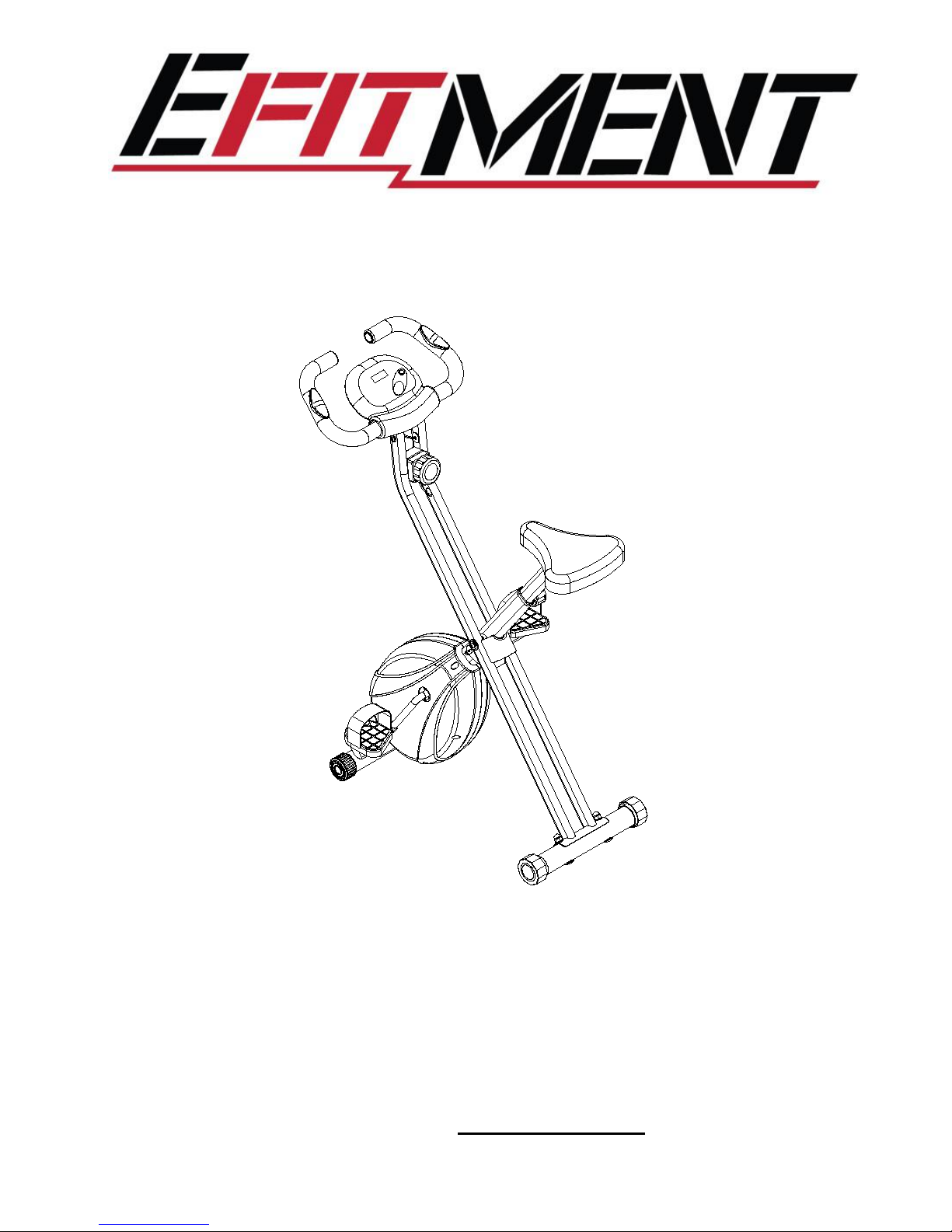
B019Magnetic TensionFolding BikeUser Manual
IMPORTANT
:
Read all instructions carefully before using this product. Retain this manual for future
reference. For customer service, contact [email protected].
Page 2
2
IMPORTANT SAFETY INSTRUCTIONS
Note the following precautions before assembling and using the machine.
1.
Assemble the machine exactly as described in the instruction manual.
2.
Before exercise, in order to avoid injuries, warm-up exercises are
recommended.
3.
Please make sure all parts are not damaged and are tightened well before use. This
equipment should be placed on a flat surface. Using a mat or other covering
material on the ground is recommended.
4.
Please wear proper clothes and shoes when using this equipment; do not wear
clothes that might catch any part of the equipment.
5.
Do not attempt any maintenance or adjustments other than those described in this
manual.
6.
Do not use the equipment outdoors. It is not a commercial model.
7.
This equipment is for household use only.
8.
This machine can be used by one person at a time.
9.
If you feel any chest pains, nausea, dizziness, or short of breath, you should
stop exercising immediately and consult your physician before continuing.
10.
This bike is intended for adult use only. Keep children away from the bike.
11.
Before beginning exercise, remove all objects within a radius of 4 feet from the machine.
12.
The maximum weight capacity for this product is 240 LBS.
WARNING: Your health can be affected by incorrect or excessive exercise. Consult a doctor
before beginning your exercise program. This machine is not suitable for therapeutic
purpose.
CAUTION:
Read all instructions carefully before operating this product. Retain
this Owner’s Manual for future reference.
WARNING: This product can expose you to one or more chemicals known to
the State of California to cause cancer and birth defects or reproductive
harm. For more information go to www.P65Warnings.ca.gov.
Page 3
3
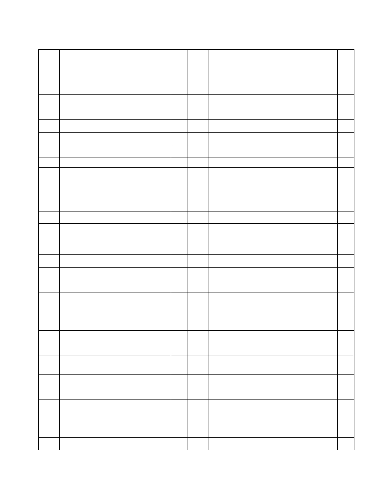
PARTS LIST
No.
Description
Qty
No.
Description
Qty
1
Main Frame
131Bearing 6203Z
2
2
Handlebar
132Bushing Φ21xΦ15.2x3.0
1
3
Meter Post
133Nylon Nut M6
1
4
Front Stabilizer Φ50x1.5
134Cap Nut M10
4
5
Magnetic Wheel Φ180x25
135Bolt M10x56
4
6
Arc Washer Φ6
236Arc Washer Φ10xΦ20x2.0
4
7
Tension Control Knob
137Flat Washer Φ6
2
8
Adjustment Knob M16
138Flat Washer Φ8
3
9
Belt 270/J4
139Outer Hexagonal Bolt M8x20
1
10
Computer
1
40
Cross Pan Head Tapping Screw
ST4.2x20
6
11
Magnetic Bracket
141Tension Spring Φ20x39xδ3.2
1
12
Seat Post Plastic Bushing
142Nylon Nut M8
4
13
Chain Cover
243Outer Hexagonal Bolt M6x20
1
14
Spring 65Mn/Φ10x45xδ1.0
144Pressure Plate
1
15
Cross Pan Head Tapping Screw
ST2.9x9.5
245Bearing 6000Z
2
16
Flat Washer Φ23xΦ35x2.0
146Flat Washer Φ5
1
17
Puller Bushing (7/8)"
147Flat Washer
2
18
Hexagonal Flat Nut (7/8)"
148Flat Washer Φ40x2.8
1
19
Belt Pulley with crank
149Handrail Arm End Cap
2
20
Left Foot Pedal (1/2)"
1
50
Handrail Arm Foam Grip Φ33xΦ23x450
2
21
Right Foot Pedal (1/2)"
151Pulse Sensors
2
22
Bearing Bush Φ55.6x16
252Circlip Φ10
1
23
Bearing Φ44.5
253Inner Pan Head Hexagonal Bolt M8x15
2
24
Inner Pan Head Hexagonal Bolt
M6x15
454Wire Plug
1
25
Seat Post
155Hexagonal Nut M6
1
26
Sensor Wire
156Flat Washer
3
27
Seat Cushion
157Cross Pan Head Screw M5x20
1
28
End Cap for Front Stabilizer
258Puller Bushing (15/16)"
1
29
End Cap for Rear Stabilizer
259Rubber Bushing
1
30
Magnetic Wheel Axle Φ17x90
160Axle Sleeve
4
Page 4

4
No.
Description
Qty
No.
Description
Qty
61
Rotation Shaft
164Rear Stabilizer Φ50x1.5
1
62
Cross Pan Head Self-tapping
Screw ST4.2x12
465Flat Washer Φ10xΦ20x2.0
1
63
Pin Φ8x60
166Wave Washer Φ15xΦ21x0.3
1
Page 5
5
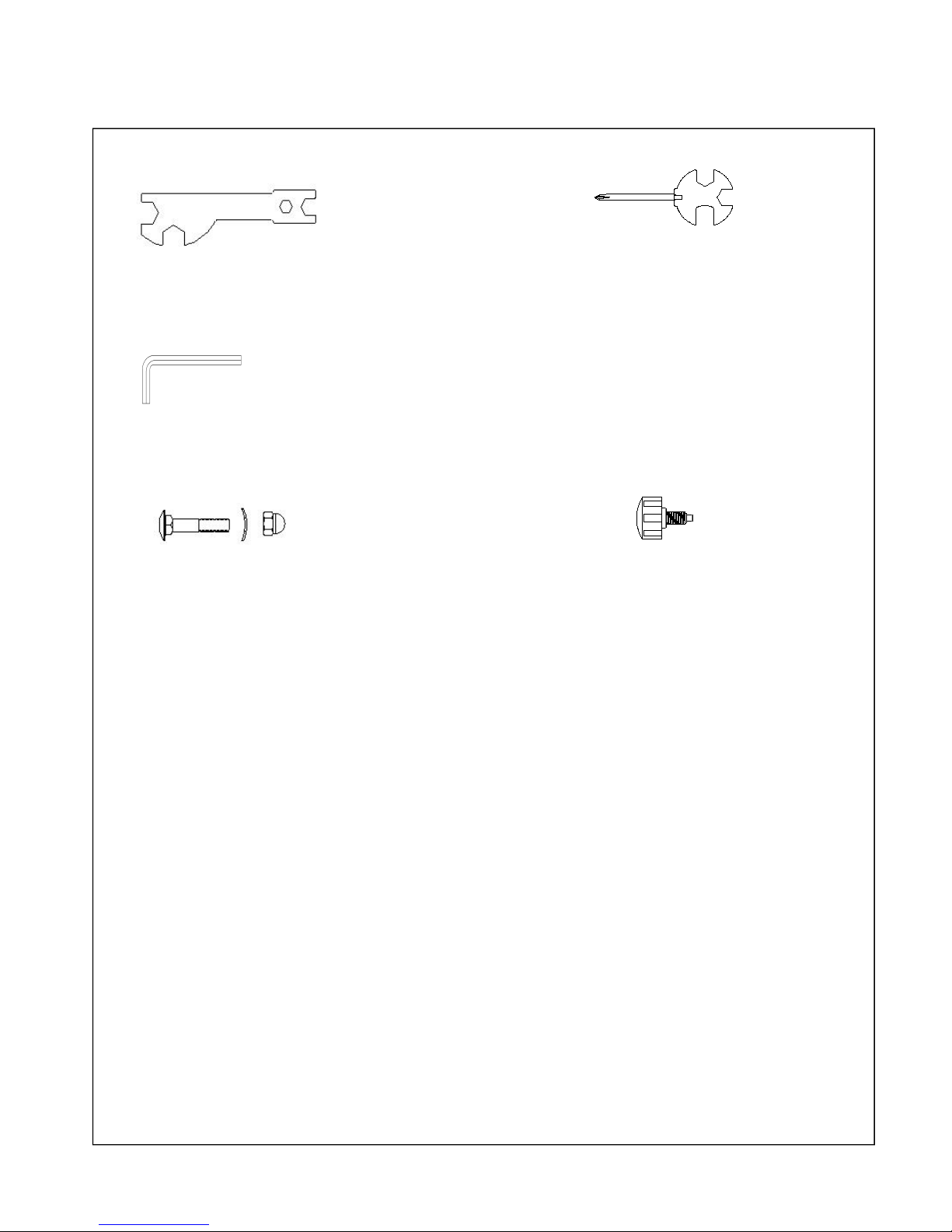
HARDWARE BAG
Spanner S10-S13-S17-S19 1PC Spanner with Phillips Screwdriver S13-S14-S15 1PC
Allen Wrench S5 1PC
(35) Bolt M10x56 4PCS (8) Adjustment Knob M16 1PC
(36) Arc Washer Ø10xØ20x2.0 4PCS
(34) Cap Nut M10 4PCS
Page 6
6
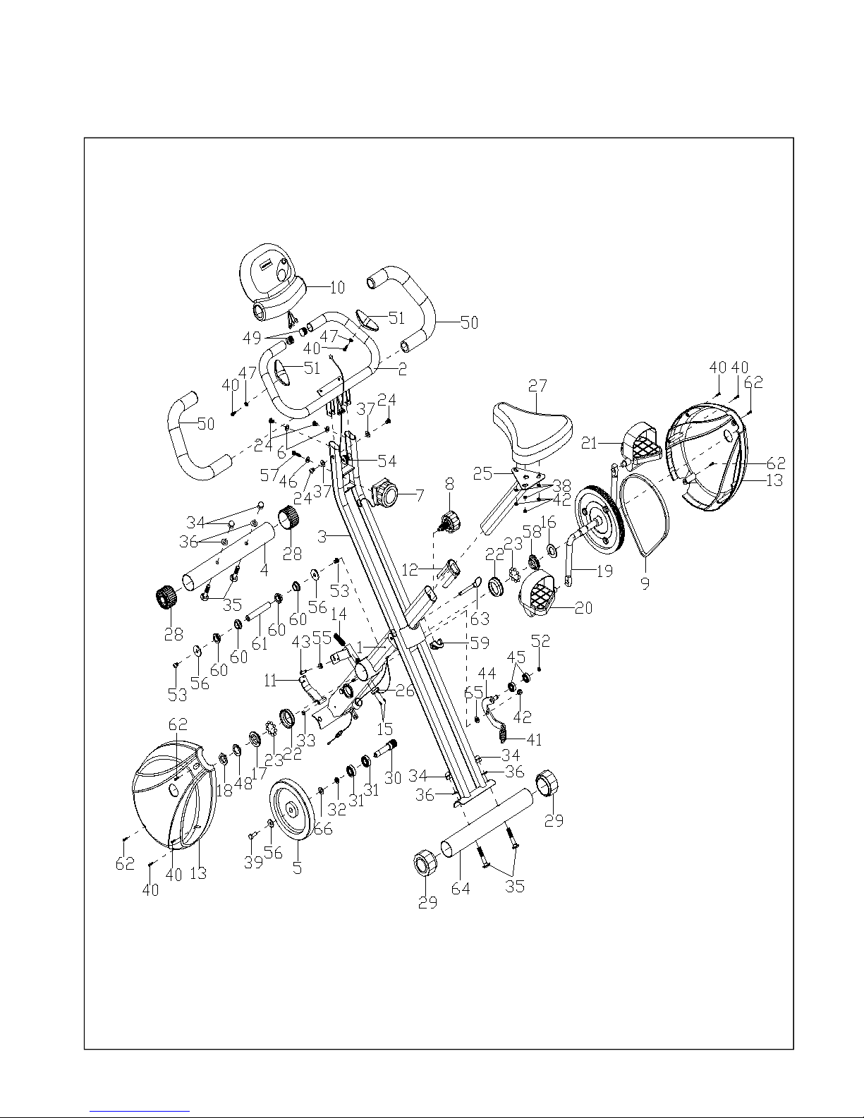
EXPLODED DRAWING
Page 7
7
ASSEMBLY INSTRUCTIONS
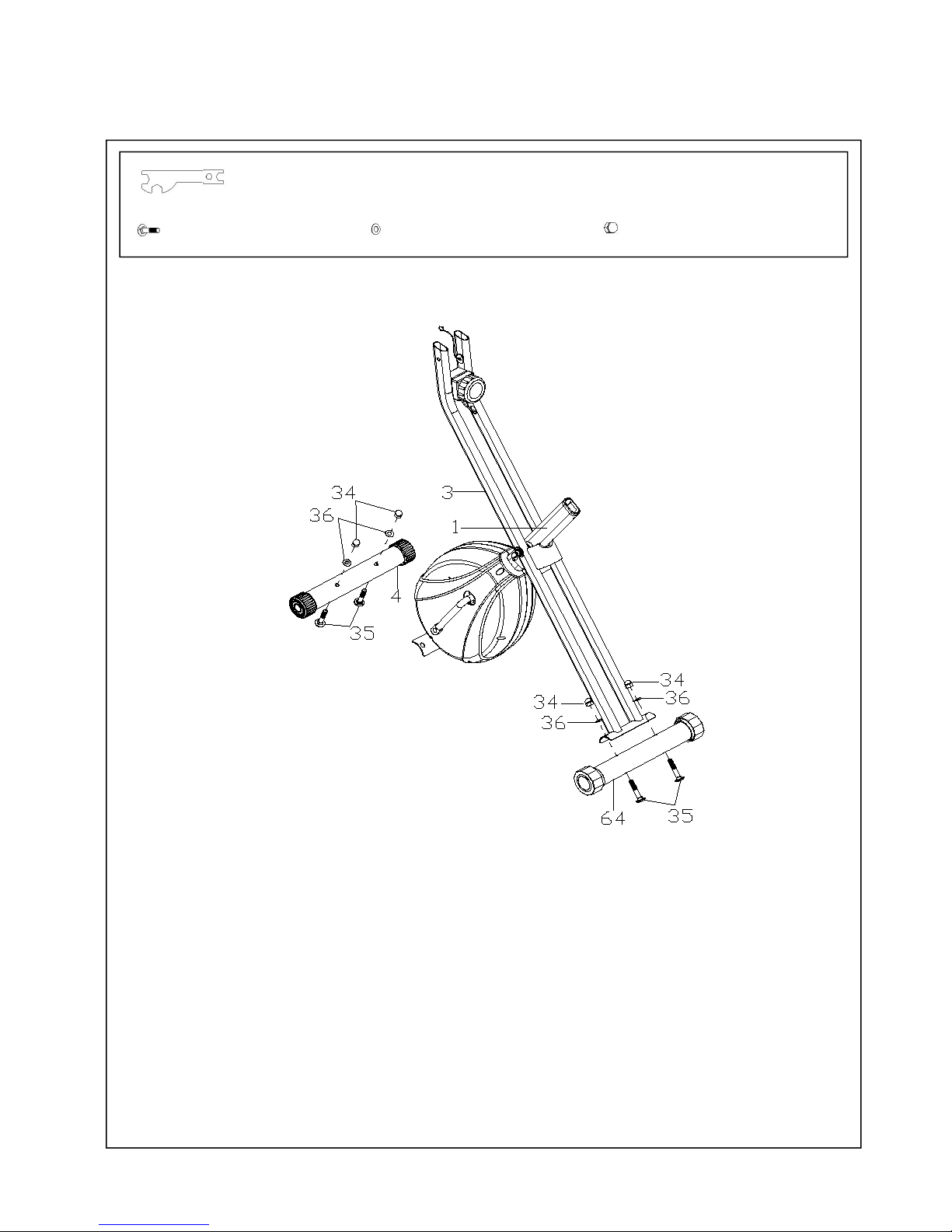
Step 1:Front and Rear Stabilizers
Position the Front Stabilizer (No. 4) in front of Main Frame (No. 1) and align bolt holes.
Attach the Front Stabilizer (No. 4) onto the Main Frame (No. 1) using 2 Bolts (No.
35), 2 Arc Washers (No. 36) and 2 Cap Nuts (No. 34). Tighten with the Spanner
provided.
Repeat the same procedure to assemble Rear Stabilizer (No. 64).
Spanner S10-S13-S17-S19
(35) Bolt M10 x 56, 4pcs (36) Arc Washer Φ10, 4PCS (34) Cap Nut M10, 4PCS
Page 8
8
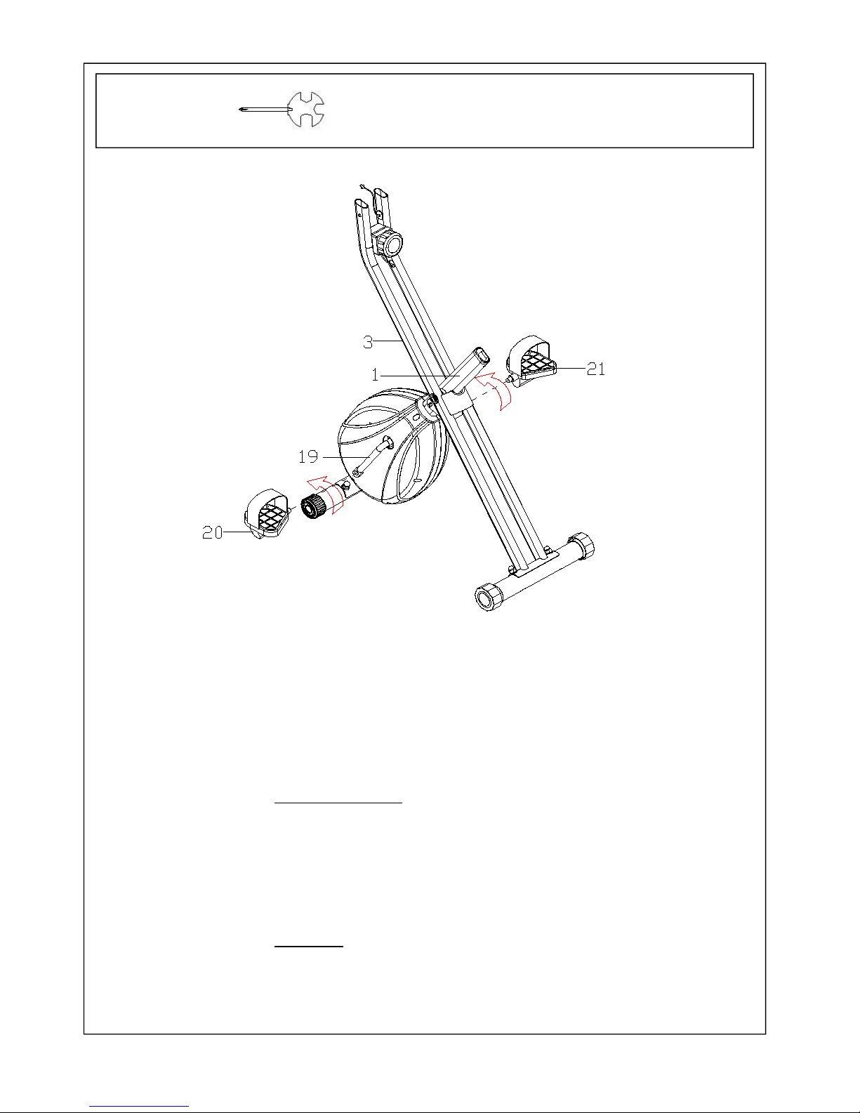
Step 2: Left and Right Foot Pedals
The Cranks, Pedal Shafts, and Foot Pedals are marked “R” for Right and “L” for Left.
Attach the Left Foot Pedal (No. 20) to the left Crank (No. 19), and turn the Left Foot
Pedal (No. 20) by hand counter-clockwise. Then tighten with Spanner with Phillips
Screwdriver provided.
Note: Do not turn the Left pedal clockwise to tighten or will strip the threads.
Attach the Right Foot Pedal (No. 21) to the right Crank (No. 19). Turn the Right Foot
Pedal (No. 21) by hand clockwise, then tighten with the Spanner with Phillips Screwdriver
provided.
Spanner with Phillips Screwdriver S13-S14-S15
Page 9
9
用盘头方劲螺栓M10*56 (35) 弧形垫片Φ20*Φ10.5(36)
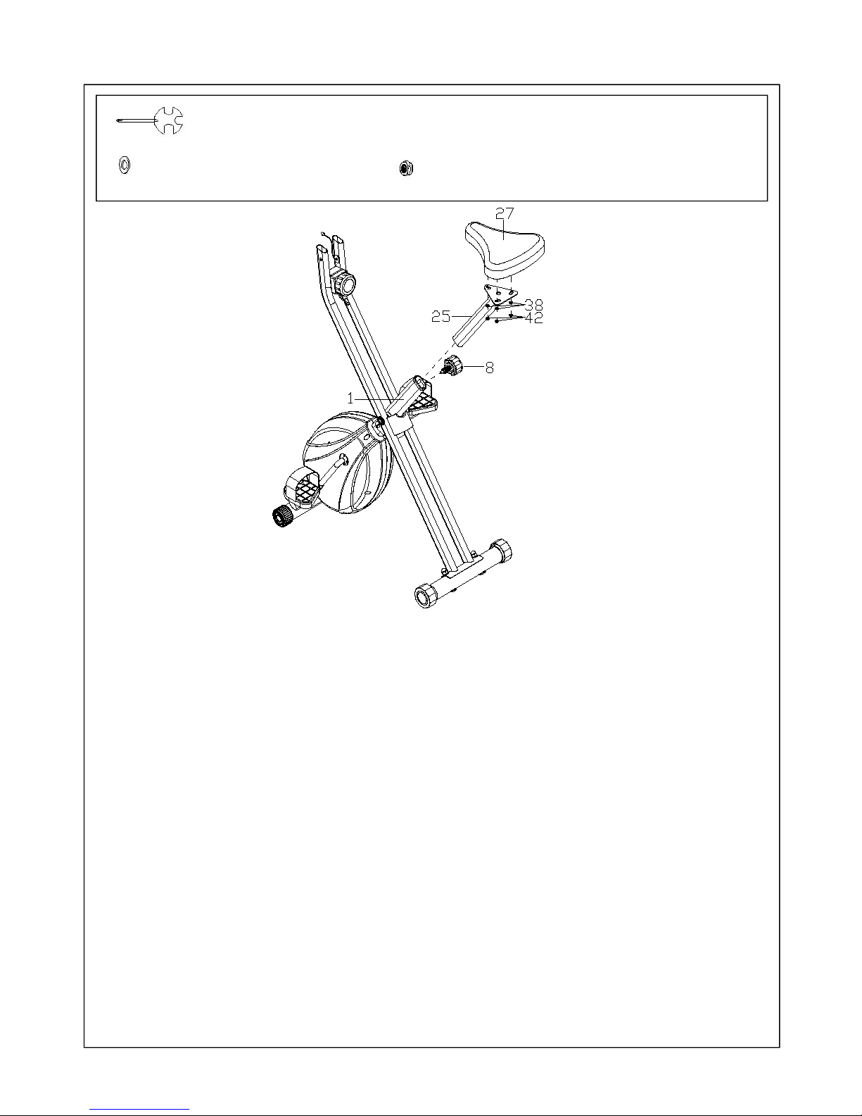
Step 3: Seat Post, Seat Cushion
Remove 3 Flat Washers (No.38) and 3 Nylon Nuts (No. 42) from under the Seat Cushion
(No. 27).
Attach the Seat Post (No. 25) to the Seat Cushion (No. 27) using 3 Flat Washers (No. 38)
and 3 Nylon Nuts (No. 42). Tighten with Spanner with Phillips Screwdriver provided.
Insert the Seat Post (No. 25) into the Main Frame (No. 1), then insert the Adjustment
Knob (No. 8). Turn Adjustment Knob (No. 8) clockwise to lock the Seat Post (No. 25) at a
suitable height.
Spanner with Phillips Screwdriver S13-S14-S15
(38) Flat Washer Φ8, 3PCS
(42) Nylon Nut M8, 3PCS
Page 10
10
S5
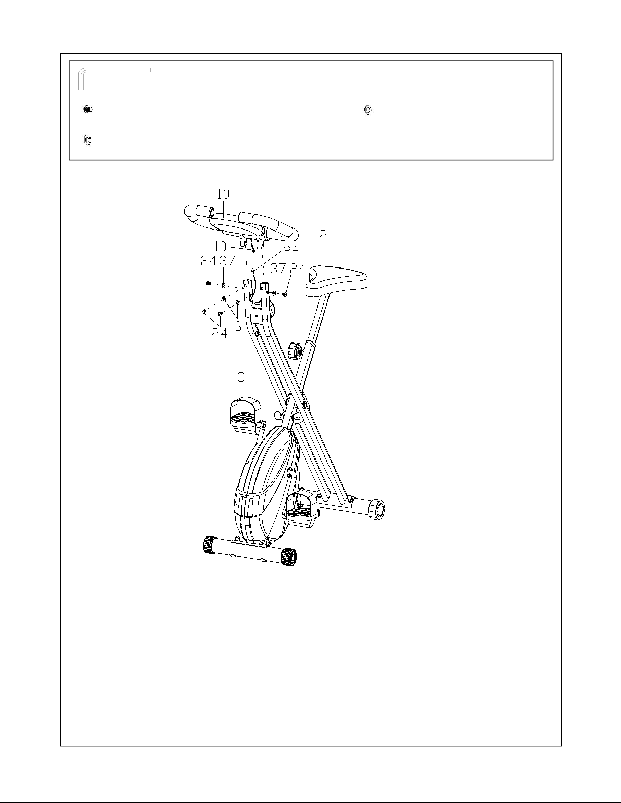
Step 4: Computer Installation
Remove 4 Inner Pan Head Hexagonal Bolts (No. 24), 2 Flat Washers (No. 37) and 1 Arc
Washer (No. 6) from Handlebar Post (No. 2).
Attach Handlebar (No. 2) onto Meter Post (No. 3) using 4 Inner Pan Head Hexagonal
Bolts (No. 24), 2 Flat Washers (No. 37) and 2 Arc Washers (No. 6). Tighten with the Allen
Wrench S5 provided.
Connect the wire that comes from Computer (No. 10) with Sensor Wire (No. 26).
Allen Wrench S5
(24) Inner Pan Head Hexagonal Bolt M6x15, 4PCS (37) Arc Washer Φ6, 2PCS
(6) Flat Washer Φ6, 2PCS
Page 11
11
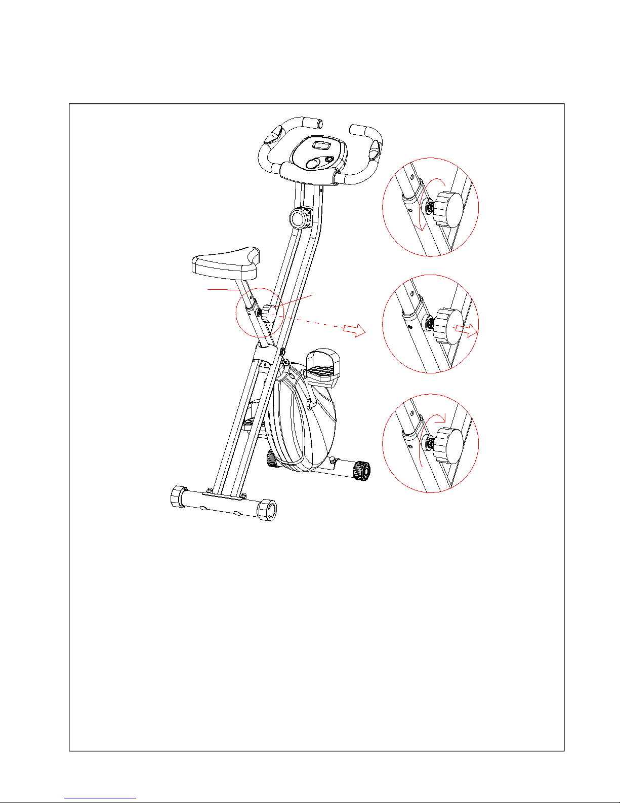
HOW TO ADJUST THE SEAT
8
25
A. Turn the Adjustment Knob (No. 8) about 1 turn counterclockwise.
B. Using one hand, pull out the knob, using the other hand, move the Seat Post (No. 25)
to the desired height.
C. Insert the Adjustment Knob (No. 8) and turn it clockwise to tighten.
Note: The Adjustment Knob (No. 8) must be tightened to prevent any accident.
CAUTION:
•Do not adjust the height of the seat post over the STOP line shown on the seat post.
•Do not reverse pedal on the bike. Reverse pedaling will damage the bike.
Page 12
12
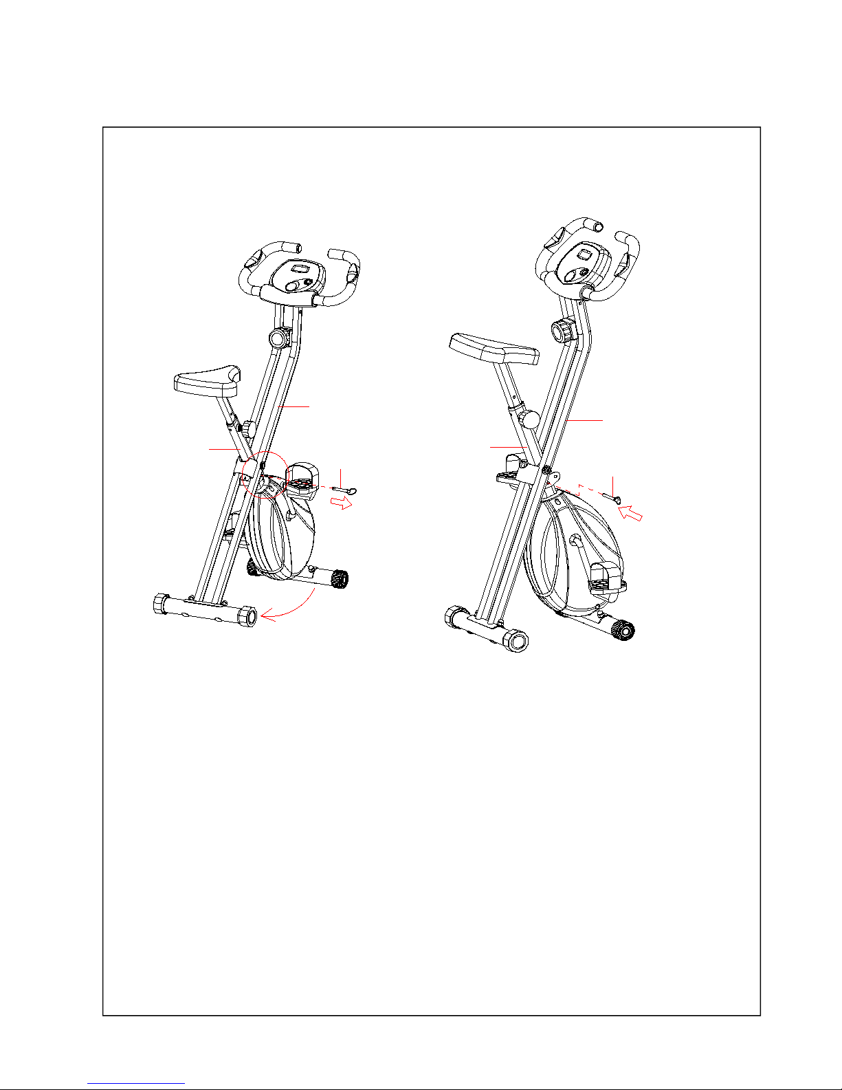
HOW TO MOVE THE BIKE
63
1
3
63
1
3
Pull out the Pin (No. 63), hold the Meter Post (No.3) by the left hand, and grasp the
Main Frame (No. 1) by the right hand and push it forward until the oval-shaped holes on
the Meter Post (No.3) and Main Frame (No. 1) align with each other. Then insert the
Pin (No. 63). (Refer to Figure B).
Figure A
Figure B
Page 13
13
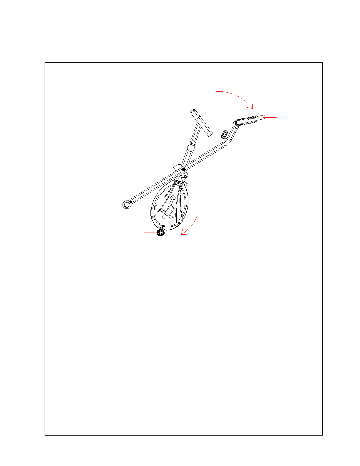
HOW TO MOVE THE BIKE
2
28
Before attempting to move the bike, please make sure that it has been properly folded.
The Pin (No. 63) must be inserted.
Put your hands on the Handlebar (No. 2), tilt the bike until the End Cap for Front
Stabilizer (No. 28) are able to move on the ground.
Now you can move the bike to the desired location with ease.
Page 14
14
ADJUSTMENTS
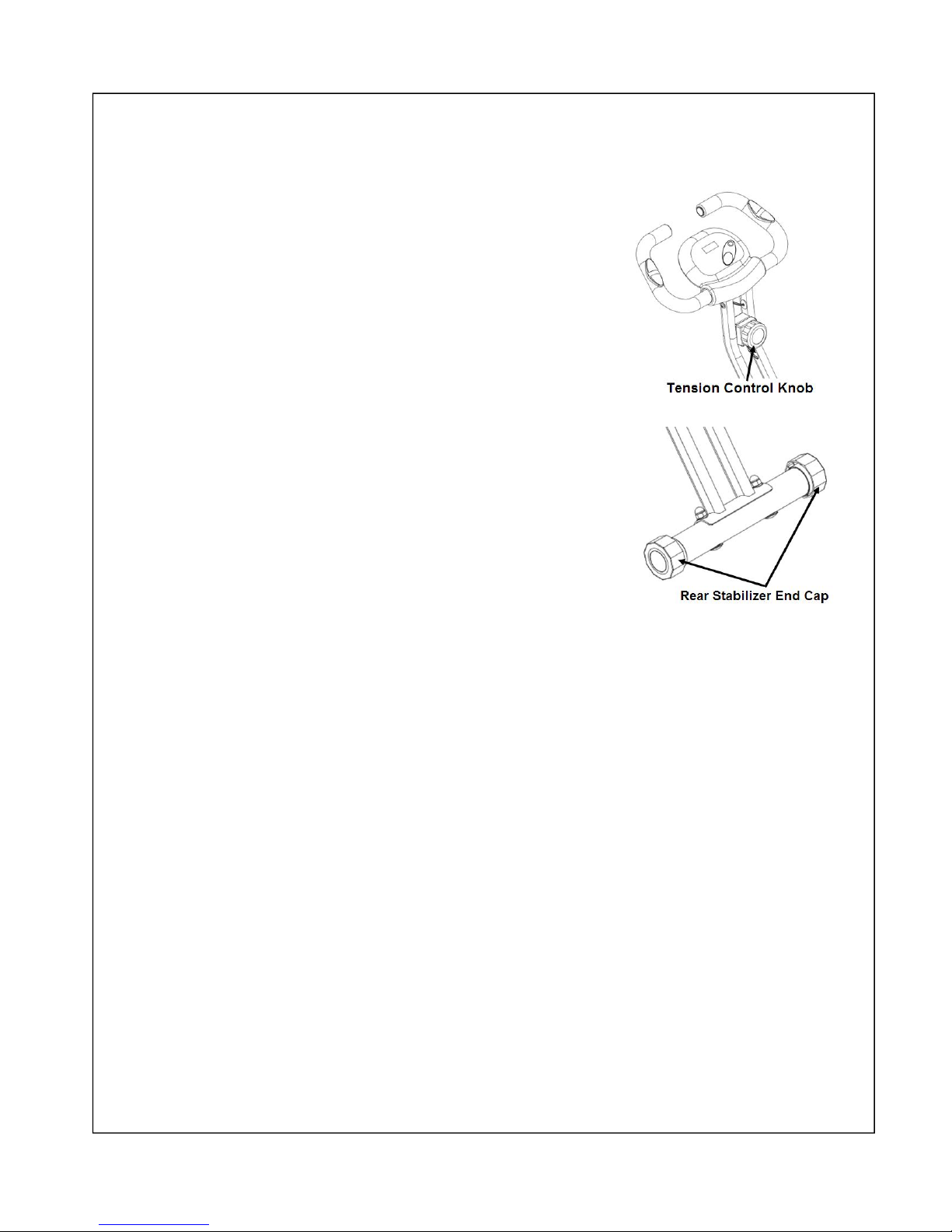
Adjusting the Tension Control Knob
To increase the tension, turn the Tension Control
Knob clockwise.
To decrease the tension, turn the Tension Control
Knob counter-clockwise.
Adjusting the Rear Stabilizer End Cap
Turn the Rear Stabilizer End Cap as needed
to level the bike.
MAINTENANCE
Cleaning
The bike can be cleaned with a soft clean damp cloth. Do not use abrasives or solvents on
plastic parts. Please wipe your perspiration off the bike after each use. Be careful not get
excessive moisture on the computer display panel as this might cause an electrical hazard or
electronics to fail.
Please keep the bike, especially the computer console out of direct sunlight to prevent screen
damage.
Please inspect all assembly bolts and pedals on the machine for proper tightness every
week.
Storage
Store the bike in a clean and dry environment away from children.
Page 15
15
TROUBLESHOOTING
PROBLEM
SOLUTION
There is no display on the computer
console.
1. Remove the computer console and verify
the wire that comes from the computer
console is properly connected to the wire
that comes from the handlebar post.
2. Check if the batteries are correctly
positioned and battery springs are in
proper contact with batteries.
3. The batteries in the computer console may
be dead. Change to new batteries.
There is no heart rate reading or heart rate
reading is erratic / inconsistent.
1. Make sure that the wire connections for
the hand pulse sensors are secure.
2. To ensure the pulse readout is more
precise, please always hold on to the
handlebar grip sensors with both hands
instead of just with one hand when you
try to test your heart rate figures.
3. Avoid gripping the hand pulse sensors
too tightly. Try to maintain moderate
pressure while holding onto the hand
pulse sensors.
The bike wobbles when in use
Turn the rear stabilizer end cap on the rear
stabilizer as needed to level the bike.
The bike makes squeaking noise when in
use.
The bolts may be loose on the bike. Please
inspect all of the bolts and tighten any loose
bolts.
Page 16
16
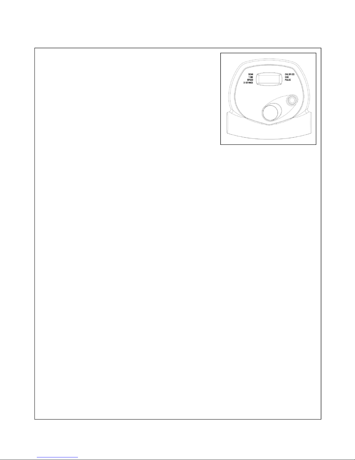
EXERCISE COMPUTER
SPECIFICATIONS
TIME--------------------------------------------------0:00~99:59MIN
SPEED-----------------------------------------------0.0~999.9ML/H
DISTANCE----------------------------------------0.00~999.9ML
CALORIE--------------------------------------------0.0~999.9KCAL
ODOMETER ---------------------------------------0.0~99.99ML
PULSE --------------------------------------------40~240BPM
KEY FUNCTIONS:
MODE: Press this button to select and lock on a particular function you want.
Press and hold MODE key for 4 seconds to reset the meter.
FUNCTIONS:
1.TIME: Press the MODE key until pointer lock in to TIME. The total exercise
time will be shown when starting exercise.
2.SPEED: Press the MODE key until pointer lock on to SPEED. Current speed will be
displayed.
3.DISTANCE: Press the MODE key until pointer lock on to DISTANCE . The
distance of this workout will be displayed.
4.CALORIE:Press the MODE key until pointer lock on to CALORIE The calorie
burned will be displayed when starting exercise.
5. ODOMETER: Automatically accumulates total accumulated distance from when batteries
are installed in the meter.
6.PULSE: Press the MODE key until the pointer advance to PULSE function
Hold pulse sensors for 3 seconds to measure pulse.
7.SCAN: Press MODE until pointer points to SCAN.
Automatically rotates display the following functions in the order shown for 4 seconds each:
TIME---SPEED---DISTANCE---CALORIE---ODOMETER ---PULSE---SCAN
NOTE:
1. The computer turns on automatically when you start pedaling or when you press MODE.
2. The computer will automatically shut off after 4-5 minutes of inactivity.
3. The monitor use 2 1.5v ”AA” batteries that are pre-installed in the meter.
4. If there is a problem with the display, try replacing the batteries first. When changing the
batteries, change both of them. Do not mix battery types. Do not mix old and new batteries.
Dispose of old batteries according to your regional guidelines.
Version 1.1
 Loading...