

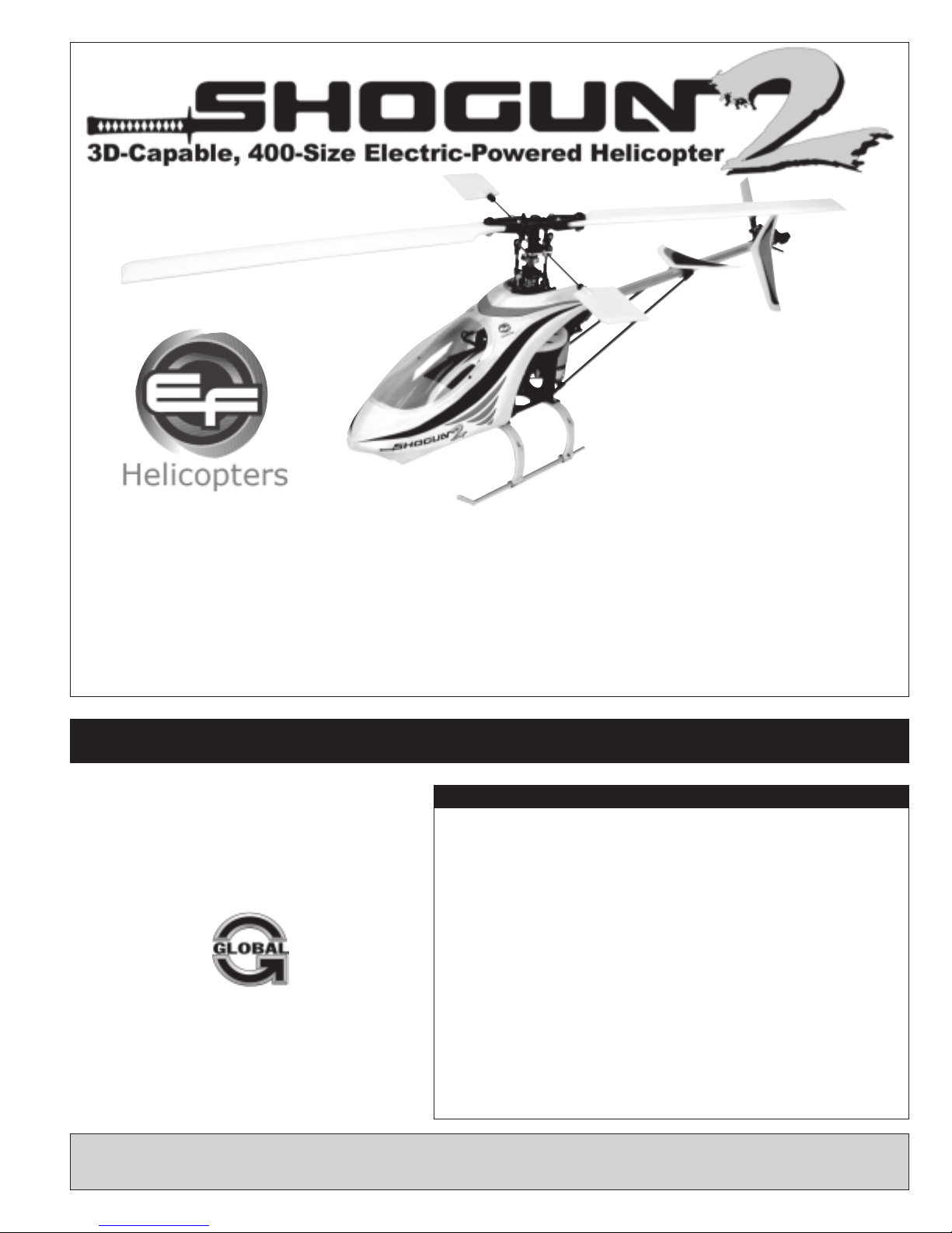
EF Helicopter Shogun 400 V2 Assembly Manual And Setup Manual
●●
●
●●
Overall Length: 780mm
●●
●
●●
Main Rotor Diameter: 645mm
●●
●
●●
Tail Rotor Diameter: 140mm
●●
●
●●
Overall Height: 200mm
●●
●
●●
WeightRTF: 520 grams (Approximate)
Shogun, the industry leader and creator of the 400-class 500 gram helicopter has once again raised the bar with the Shogun 400 V2. We've taken a
great heli and made it better with all the parts and features loyal Shogun owners have asked for! Leading this long list of upgrades is the new belt drive
system for driving the tail rotor. The belt drive provides a strength and durability level not achievable with a shaft drive design.
But we did not stop there! We packed the Shogun 400 V2 with tons of features you want! Lightweight flybar paddles make the cyclic controls fast
without loosing the stability and smoothness that makes the Shogun so rewarding to fly. We've also widened the landing gear,updated the body style,
included ball linkages for the controls, shifted the tail rotor servo position to the tail boom, and even extended the battery tray to make it easier to i nstall
your favorite LiPO battery.
All of this, combined with our complete line of after-market accessories, as well as our extensive dealer network and online support, means you can
do whatever you want with your Shogun and we'll be there to back you up with the service and parts you want! Get a Shogun and find out what the
world of performance electric helicopters is really all about! Performance, Reliability, and Excitement!
ASSEMBLY MANUAL AND SETUP GUIDE
FEATURESAND SPECIFICATIONS:
●
90% Factory-Assembled w/Balanced Main Rotor Blades
●
Belt Drive TailRotor
The EF Helicopters Shogun 400 V2 helicopteris distributed
exclusively by Global Hobby Distributors
18480 Bandilier Circle, Fountain Valley, CA 92708
All contents copyright © 2005, Global Hobby Distributors
Version V1.0 June 2005
Kit Product Number: 163110
●
Lightweight Paddles
●
Boom-Mounted Tail Rotor Servo
●
Wide Landing Gear Stance
●
Fiberglass Composite Main Frame
●
Strong, Lightweight Aluminum Tail Boom
●
3D-Aerobatic, Collective Pitch, 6-Channel Control
●
Ball-End Control Linkages
●
Extended Aluminum Battery Tray
●
Durable Tail Boom Supports
●
Complete Ball Bearing Set
●
Online Parts Support
●
Extensive Hop-Ups and After-Market Parts Available
The EF Helicopters Shogun 400 V2 helicopter is not intended for first-time helicopter pilots. Although it may be possible to
learn to fly using this helicopter with an experienced instructor, the helicopter is designed for more experienced pilots.
1
CUSTOMER SERVICE INFORMATION
If you should find a part missing or damaged, or have any questions about assembly, please contact us at the address below:
Global Services
18480 Bandilier Circle
Fountain Valley,CA 92708
Phone: (714) 963-0329
Fax: (714) 964-6236
Email: service@globalhobby.net
CHECK IT OUT! We urge you to come check out our website at http://globalservices.globalhobby.com. There you will find public message
boards frequented by other EF Helicopters product owners and the EF Helicopters support staff. This is a great place to learn about new products,
get help and suggestions for your current EF Helicopters products or just simply hang out and chat with people that share your same interests.
To enable us to better serve your needs, please include your email address with any correspondence you send to us. Your email
address will be added to our Customer Service Database so you will automatically receive free updates and tech notices for your
particular product. You will also receive repair status updates (if applicable) and other important information about your product as it
becomes available.
IMPORTANTINFORMATION ABOUT YOUR EMAILADDRESS
Global Hobby Distributors will not disclose the information it collects to outside parties. Global Hobby Distributors does not sell,
trade, or rent your personal information to others . Your privacy is important to us.
WARNING - PLEASE READ BEFORE PROCEEDING
This R/C helicopter is not a toy! If misused or abused, it can cause serious bodily injury and/or damage to property. Fly only in open areas and preferably
at a dedicated R/C flying site. We suggest having a qualified instructor carefully inspect your helicopter before its first flight. Please carefully read and
follow all instructions included with this helicopter, your radio control system and any other components purchased separately.
●
Just because the Shogun 400 V2 helicopter is powered by an electric motor doesn't mean that you shouldn't exercise caution when flying and
operating it. Youmust use the same amount of caution during use as when flying and operating a glow-powered helicopter.
●
We strongly suggest that when you first begin flying the Shogun 400 V2 helicopter that you perform only basic maneuvers, such as hovering, until you
are more familiar with the setup and flight characteristics of the helicopter. This will give you time to feel comfortable with the way the helicopter reacts
to control inputs and power.
●
You must be cautious when plugging the flight battery into the helicopter. Unlike glow-powered helicopters that use a clutch assembly to allow the
engine to idle without the rotor blades spinning, an electric helicopter features no such clutch. You must be sure that your transmitter is turned on and the
power/collective control stick is in the full idle position before plugging in the flight battery. Thiswill prevent any chance of the rotor blades spinning and
harming you while plugging in the flight battery.
LITHIUM POLYMER BATTERY WARNINGS - PLEASE READ BEFORE CHARGINGAND USE
●
LiPO batteries m ay explode or catch fire. Serious injury can result from misuse.
●
All instructions, warnings and cautions must be followed at all times. Failure to do so can lead to serious injury or fire.
●
Do NOT overcharge. Maximum voltage for each pack must be followed.
●
Do NOT over-discharge. NEVER discharge below minimum volts.
●
Do NOT discharge at a rate greater than the maximum continuous discharge.
●
Do NOT use or charge if the battery is hot.
●
ONLYuse a charger made for Lithium Polymer batteries.
●
Do NOT charge at a rate higher than 1C. Example: if the battery’s rating is 340mAH, then the charger’s charge rate must be set at 340mAH or less.
●
Do NOT leave in direct sunlight or in a hot car or storage area.
●
Do NOT get wet or expose to moisture.
●
Do NOT short-circuit the battery.
●
ONLYdischarge and charge the battery outdoors or in a fire-safe container.
●
Do NOT charge with reverse polarity.
●
Do NOT leave the battery connected when not in use.
●
Do NOT operate or charge unattended.
●
Do NOT solder to the battery directly and do not get the battery hot in any way.
●
Always let the battery cool and "rest" between uses and charging.
●
Do NOT charge inside your car or inside your house.
●
Inspect the battery before each use for swelling or other malformation. If the cell has ballooned, it MUST be discarded.
●
Set the charger to 1C (charge at 1/2C or less for the first 5 cycles).
●
Check polarity and then connect battery to charger.
●
In use, do not over-discharge or exceed maximum discharge.
●
When handling the battery, remember not to poke, bend or damage the cell. The cell outer casing is soft and can be damaged.
●
Remember, the cells must never exceed 160 degrees Fahrenheit for any reason.
2
ITEMS NEEDED FOR ASSEMBLY
This section describes our recommendations to help you decide which accessories to purchase for your Shogun 400 V2 helicopter.
Remember, this helicopter is small, lightweight and 3D-capable. When choosing accessories, we suggest choosing the lightest
available. The lighter the overall weight of the helicopter, the better it will fly.
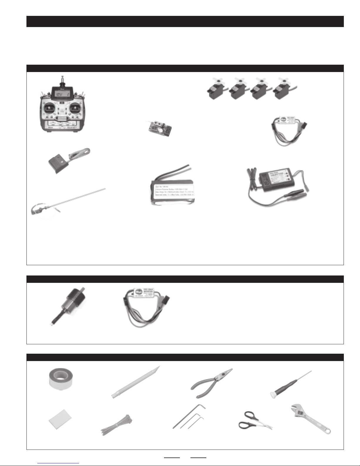
RECOMMENDED ITEMS FOR FLIGHT
6 Channel or More
Heli-Capable Transmitter
Hitec Eclipse 7 Transmitter
or Equivalent
(Should Feature Throttle/Collective
Mixing & Throttle Hold)
P/N 443536
Cirrus CS-10BBHD Micro Servos or Equivalent
(Should Be 8-10 Grams and Feature Ball Bearings)
Receiver uses Cirrus single
conversion FM Crystal
(not included).
P/N 444053
P/N 165020
Cirrus MRX-6 FM Micro Receiver
or Equivalent
(Use Micro Receiver Only)
P/N 444509
EF Helicopters ESC-20AH
Micro ESC or Equivalent**
Cirrus MPG-6 Micro Gyro or Equivalent
(Use Micro Gyro Only)
P/N 625112
Dean's Whip Antenna (Optional)
P/N 128763
WattAge 3 Cell 1250mAH - 2000mAH
LiPO Battery or Equivalent
ProPeak Quattro LiPO Charger
or Equivalent*
P/N 158370
*You must use a LiPO-compatible charger to charge LiPO batteries. Do not attempt to charge LiPO batteries with a charger not specifically designed
to charge LiPO batteries.
**We recommend the EF Helicopters ESC-20AH ESC because it's designed for use with electric helicopters and specifically for LiPO batteries. This
ESC features an on/off switch, smoother start and acceleration, no motor cutoff and an ultra-bright red LED to indicate when it's time to land. It's got
a small footprint and is very light, too.
RECOMMENDED ITEMS FOR BRUSHLESS MOTOR SETUP
While the Shogun V2 is 3D-capable out of the box, if you really
want to ratchet up the power for ultra-extreme 3D aerobatics, we
highly suggest upgrading to our brushless power system. This
system drops right in, and it uses the same recommended LiPO
P/N 165370
EF Helicopters
Brushless Motor w/Pinion Gear
EF Helicopters
Brushless Micro ESC
P/N 165022
TOOLS AND SUPPLIES REQUIRED
Double-Sided Foam Tape
Velcro®Strip
X-Acto Knife
Nylon Cable Ties Assorted Hex Wrenches
NOTE: Asoldering iron and solder may be necessary if you need to change and/or add compatible plugs to your ESC and battery.
battery. The only other addition is the use of a brushless* ESC.
*You must use a brushless-compatible ESC with the brushless motor. Do
not attempt to use a standard ESC with the brushless motor. It won't work.
Needle Nose
Pliers
Adjustable
Scissors
Small Phillips
Screwdriver
Wrench
3
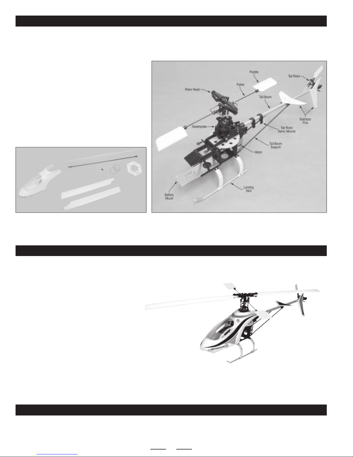
PARTS IDENTIFICATIONAND FAMILIARIZATION
If you find any parts missing or damaged, please contact us as soon as possible,
❑ (A) Shogun 400 V2 Helicopter - 1
❑ (B) Main Rotor Blades - 2
❑ (C) Body with Clear Canopy - 1
❑ (D) Tail Rotor Pushrod - 1
❑ (E) Antenna Support Tube - 1
❑ (F) Ball-End Mounts with Screws - 4
❑ (G) Rubber Bands - 2
❑ (H) Pitch Gauge - 1
❑ (I) Decal Set (Not Shown) - 1
using the Customer Service Information on page # 2.
E
C
D
F
G
A
H
B
FINAL ASSEMBLY SEQUENCE
Now that you're familiar with the main component-partsof your new Shogun 400 V2 helicopter,it's time to get started finishing it. There's
really not much to it. Below we outline the main steps for your convenience:
●
Install Your Servos
●
Install Your Gyro, Electronic Speed Control and Receiver
●
Install Your Battery
●
Adjust the Tail Rotor Belt Tension
●
Connect the Pushrod Linkages and Install the Tail Rotor Pushrod
●
Install the Main Rotor Blades
●
Apply the Decals
●
Install the Body
●
Balance the Helicopter
●
Test Controls for First Flight and Set Up YourTransmitter
If you'd like to convert your Shogun 400 V2 helicopter from belt
drive to solid carbon shaft drive, please see page # 17.
ASSEMBLY DRAWINGS AND REPLACEMENT PARTS INFORMATION
This assembly manual includes a complete set of 3D assembly drawings, a photo-illustrated replacement parts list and a
photo-illustrated hop-ups and option parts list. These sections begin on page # 14. Please save this manual and refer to these sections
if you ever need to order replacement parts or fix any problems with your helicopter.
4
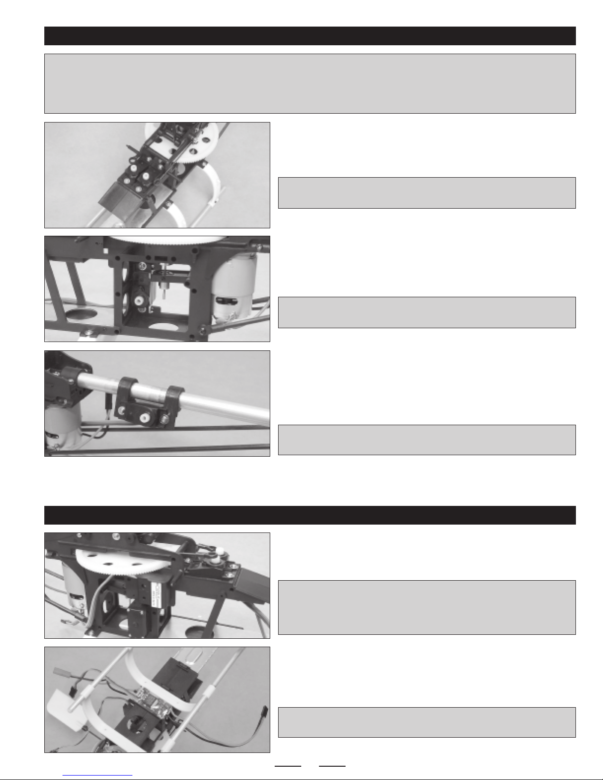
INSTALLING YOUR SERVOS
✦✦
✦IMPORTANT
✦✦
dual-ended mounting lugs, you will need to drill new 1/16" diameter holes through the frame to install the mounting screws.
For the best control response and reliability, it's important to make sure that you use high-quality, ball bearing microservos. Wedon't
recommend using bushing-supported servos, or control response and reliability will be compromised.
✦✦
✦ The helicopter frame is predrilled to fit servos with single-ended servo mounting lugs. If the servos you use have
✦✦
❑ Installyour pitch (elevator) and roll (aileron) servos into the servo mounts
at the front of the main frame.
✦✦
✦IMPORTANT
✦✦
the helicopter, so that the linkages will line up with the servo arms correctly.
❑ Install your collective servo into the servo mount in the side of the main
frame. If you're installing a servo with single-ended servo mounting lugs,
make sure to install the servo in the holes closest to the front of the frame.
✦✦
✦IMPORTANT
✦✦
of the helicopter, so that the linkage will line up with the servo arm correctly.
✦✦
✦ Both servo output shafts MUST be toward the FRONT of
✦✦
✦✦
✦ The servo output shaft MUST be toward the BOTTOM
✦✦
❑ Install your tail rotor (rudder) servo to the two servo mounting beams on
the tail boom. Again, you may need to drill new holes through the mounting
beams to fit your particular servo.
You may need to loosen the screws in the servo mounting beam clamps,
☞
so that you can adjust the width of the beams to fit your servo.
✦✦
✦IMPORTANT
✦✦
the helicopter.
✦✦
✦ The servo output shaft MUST be t oward the BACK of
✦✦
INSTALLING YOUR GYRO, ELECTRONIC SPEED CONTROL AND RECEIVER
❑ Mount your gyro to the right side of the main frame, in the small mounting
space below the main drive gear and directly above the top of the collective
servo, using a piece of double-sided foam tape.
✦✦
✦IMPORTANT
✦✦
correct direction (see your gyro installation guide for more information).
Making sure that the gyro is installed in the correct direction will ensure
that the gyro moves the tail rotor in the correct direction.
✦✦
✦ When installing your gyro, make sure to install it in the
✦✦
❑ Mount your ESC to the bottom of the main frame, in the mounting space
directly behind the forward landing gear strut, using a piece of double-sided
foam tape.
✦✦
✦IMPORTANT
✦✦
sure that the red LED points down so that you can see it during flight.
5
✦✦
✦ If you're using the EF Helicopters ESC-20AH, make
✦✦
Continued On Next Page
☛☛
☛
☛☛
❑ Mount your receiver to the mounting space in front of the pitch and roll
servos, using a piece of double-sided foam tape.
✦✦
✦IMPORTANT
✦✦
lead mounting pins are toward the right side of the main frame. Thiswill
make it easier to connect the servo leads.
❑ Plug your servos, gyro, electronic speed control and ESC leads into their
proper slots in your receiver (see chart below).
❑ Using nylon cable ties, carefully tie the servo wires together neatly to
ensure that they don't hang loose and can't interfere with any mechanical
parts, especially the main drive gear.
Double-check with your radio control system manual forthe correct channel slots in your receiver to plug the servo leads into. Most
receivers will be like the following, but yours could differ:
Roll Servo ------------ Channel 1
Pitch Servo ---------- Channel 2
ESC Throttle--------- Channel 3
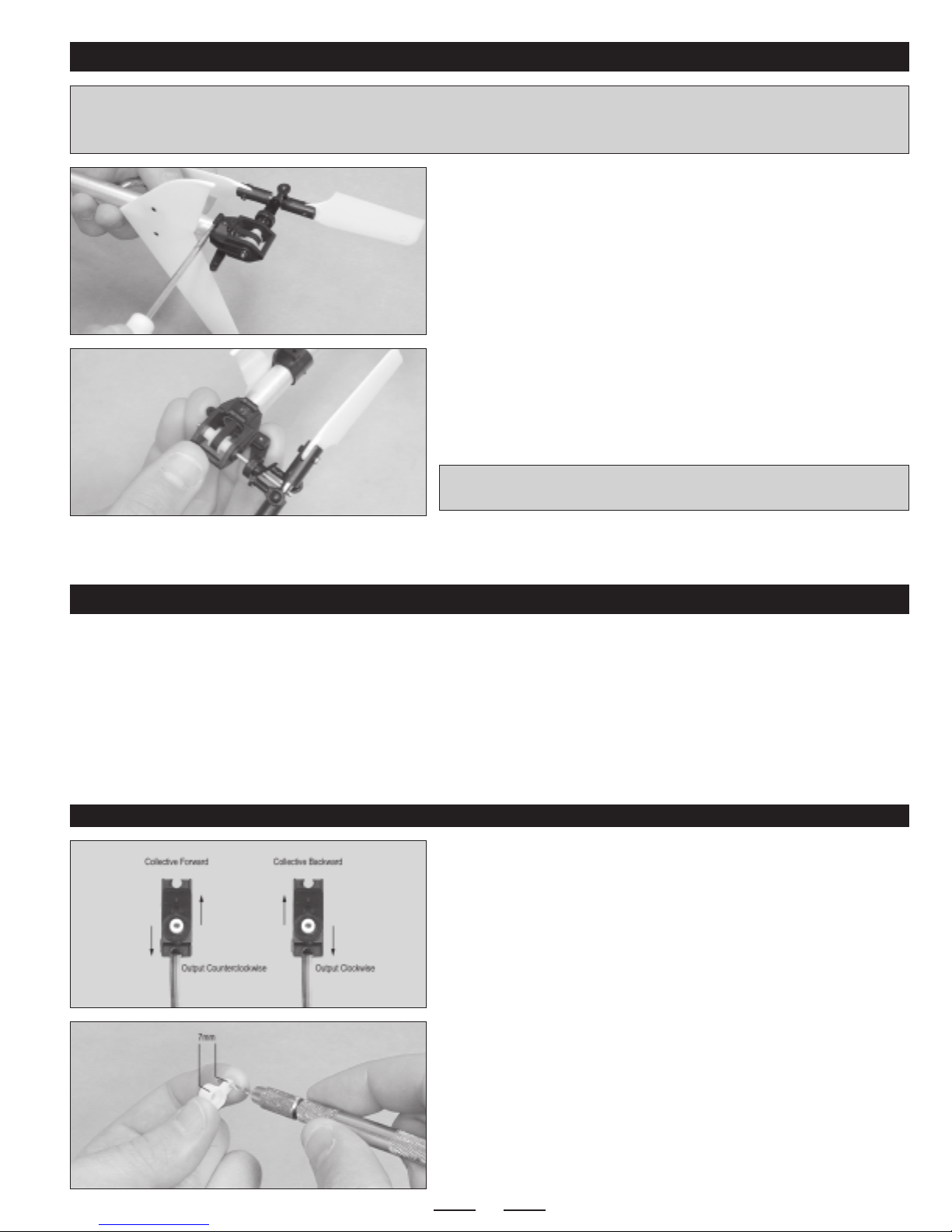
❑ Snap the plastic antenna tube into the brackets on one side of the
landing gear struts, then run the antenna through the tube and secure it to
the vertical stabilizer, using a rubber band (not included).
✦✦
✦ Wheninstallingyourreceiver,makesure that the servo
✦✦
Gyro -------------------- Channel 4
Collective Servo --- Channel 6
Tail Rotor Servo ---- Gyro
As an alternative, you could also purchase and install a whip antenna,
☞
like the one shown on page # 3.
✦✦
✦IMPORTANT
✦✦
themainrotorbladesor thetail rotor. Because of the length of the antenna, we wrapped the first few inches around an antenna bobbin,
so that there was no excess that would hang past the tail rotor and get cut off.
✦✦
✦ When securing your antenna to the helicopter, it's very important that the excess antenna cannot be drawn into
✦✦
INSTALLING YOUR BATTERY
✦✦
✦IMPORTANT
✦✦
to understand those warnings could cause failure of your battery, resulting in damage to the battery, your battery charger or even to
yourself. Do not leave the battery unattended during the charging process.
❑ If necessary, install a connector onto your battery that is compatible with the battery connector on your ESC.
✦✦
✦ Before charging your battery,it'svery important to read and fully understand the warnings listed on page# 2. Failure
✦✦
❑ Fully charge your battery, then set it onto the battery mount and secure it
into place, using the two rubber bands included.
6
Continued On Next Page
☛☛
☛
☛☛
ADJUSTING THE TAIL ROTOR BELT TENSION
✦✦
✦IMPORTANT
✦✦
could fail, and the drive-train can bind, causing loss of power and control. If the belt tension is too loose, the belt could slip and cause
loss of control.
✦✦
✦ It's important to make sure that tail rotor belt tension is set properly. If the belt is too tight, the gears and/or the belt
✦✦
❑ Loosen the retaining screw in the side of the tail gear case, then loosen
the two upper screws that hold the tail gear case halves together.
❑ Adjust the rotor belt tension by adjusting the location of the tail gear case
assembly on the boom either forward or backward. When adjusted properly,
the rotor belt should be taught, but not so tight that the assembly binds when
the main rotor is turned.
❑ When satisfied with the alignment, tighten all of the screws.
✦✦
✦IMPORTANT
✦✦
rotor is lined up 90º to the main rotor. See page # 11.
✦✦
✦ Before retightening the screws, make sure that the tail
✦✦
CONNECTING THE FLIGHT CONTROL LINKAGES
Even though it's pretty straightforward, take your time when connecting the flight control linkages. Here are a few things to remember:
●
Before installing the servo arms, the servos MUST be centered.
●
Before attaching the control linkage wires to the ball-links, the particular control system that you're working on MUST be centered.
●
The ball-links MUST be installed the specified distance from the center of the servo arms.
●
The servo reversing settings in your transmitter MUST be set properly, so that the servo arms move in the correct direction.
●
Make sure that your radio transmitter is set to heli mode and that collective mixing is turned ON.
INSTALLING THE COLLECTIVE CONTROL LINKAGE
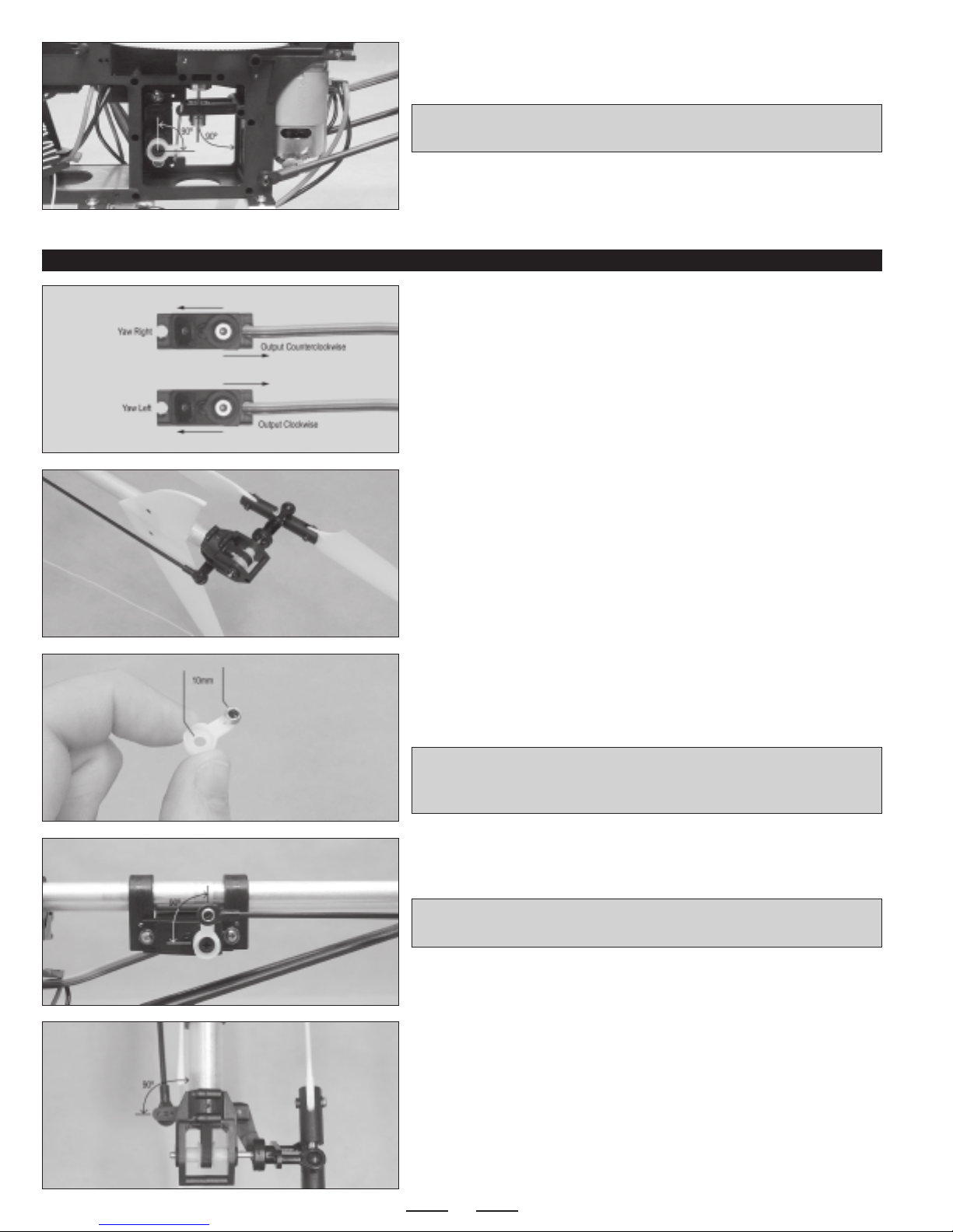
❑ Turn on your radio control system and center the collective servo. It's
important that the collective stick on your transmitter is centered, too.
❑ Double-check that the collective servo is moving in the correct direction.
When the collective stick is moved forward, the servo output shaft should
rotate counterclockwise.
❑ Cut away all but one arm from a servo horn.
❑ Enlarge the hole in the servo arm that is 7mm out from the center of the
servo horn, just large enough to fit the diameter of the collective control
linkage wire.
7
Continued On Next Page
☛☛
☛
☛☛
❑ Connect the Z-Bend in the collective control wire to your servo arm, then
attach the servo arm to the servo.
✦✦
✦IMPORTANT
✦✦
the servo and the collective pitch plate should be 90º to the vertical frame post.
❑ Install the servo arm retaining screw, then move the collective up and
down several times to ensure smooth operation.
INSTALLING THE TAIL ROTOR CONTROL LINKAGE
❑ Turn on your radio control system and center the tail rotor servo.
❑ Double-check that the tail rotor servo is moving in the correct direction.
When the yaw stick is moved right, the servo output shaft should rotate
counterclockwise.
❑ Snap one end of the tail rotor pushrod onto the ball-link that's preinstalled
on the tail rotor control arm.
✦✦
✦ When set up properly, the servo arm should be 90º to
✦✦
❑ Cut away all but one arm from a servo horn.
❑ Install one ball-link into the hole that is 10mm out from the center of the
servo horn, using the small screw provided.
✦✦
✦IMPORTANT
✦✦
thread into, you will need to use a machine screw and nut to install the
ball-link to the servo arm.
❑ Attach the servo arm to the servo, then snap the end of the tail rotor
pushrod onto the ball-link.
✦✦
✦IMPORTANT
✦✦
the servo.
You may need to slide the servo mount assembly forward or backward,
☞
so that you can attach the tail rotor pushrod to the ball-link.
❑ With the servo arm centered, carefully slide the servo mount assembly
forward or backward until the tail rotor control arm is 90º to the tail boom.
✦✦
✦ If the hole in your servo arm is too large for the screw to
✦✦
✦✦
✦ When set up properly, the servo arm should be 90º to
✦✦
8
Continued On Next Page
☛☛
☛
☛☛
 Loading...