

Effitherm AWT9-V5+, AWT13-V5+, AW11-V5+, AWT11-V5+, AW13-V5+ User Manual
...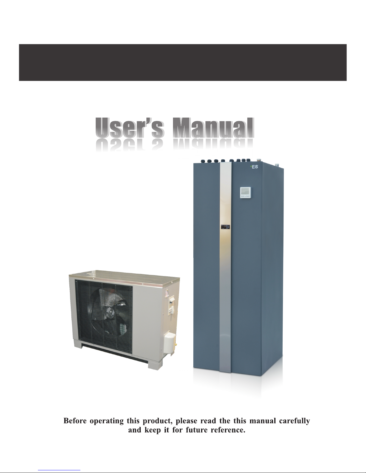
Air/water/tank 9/11/13kw Split Heat Pump

Catalogue
1.Before use
1.
2. Safety precautions
3.
4.
5.
6. Specifications
7.
List of accessories
Main components
Outlines and dimensions
Working principles
Exploded view
4
5
8
10
14
14
17
2.Installation
1.
2. Installation of the indoor unit
3. Installation of the outdoor unit
4. Refrigerant pipe connection
Quick connector
Flare nut
5. Water pipe connection
.
7. Air purging of water system
8. Pre-Start up
Installation methods
6 Installation of the accessories
FOUR-way safety valve kit
L type decorative panel in back side
Pipings for mixture valve
9. Power supply and electric connections
22
31
32
34
36
37
39
40
40
41
41
42
44
45
4
22
3.Use
1. Introduction of wired controller
3. Basic operation
4. Advanced setting
5. Failure code
6.
2. Parameter setting overview
Error code
7. Electric heating
46
46
48
53
65
75
76
81
1
02

4.Service and maintenance
1. Attention
.
3. Maintenance
2 Service
Indoor unit
Outdoor unit
Cleaning of water filter
Cleaning of heat exchanger
Gas charging
Cleaning of plate exchanger
Antifreeze in winter
4. Troubleshooting
83
5.Wiring diagram
89
83
84
84
84
86
86
86
86
87
87
87
Catalogue
1
03
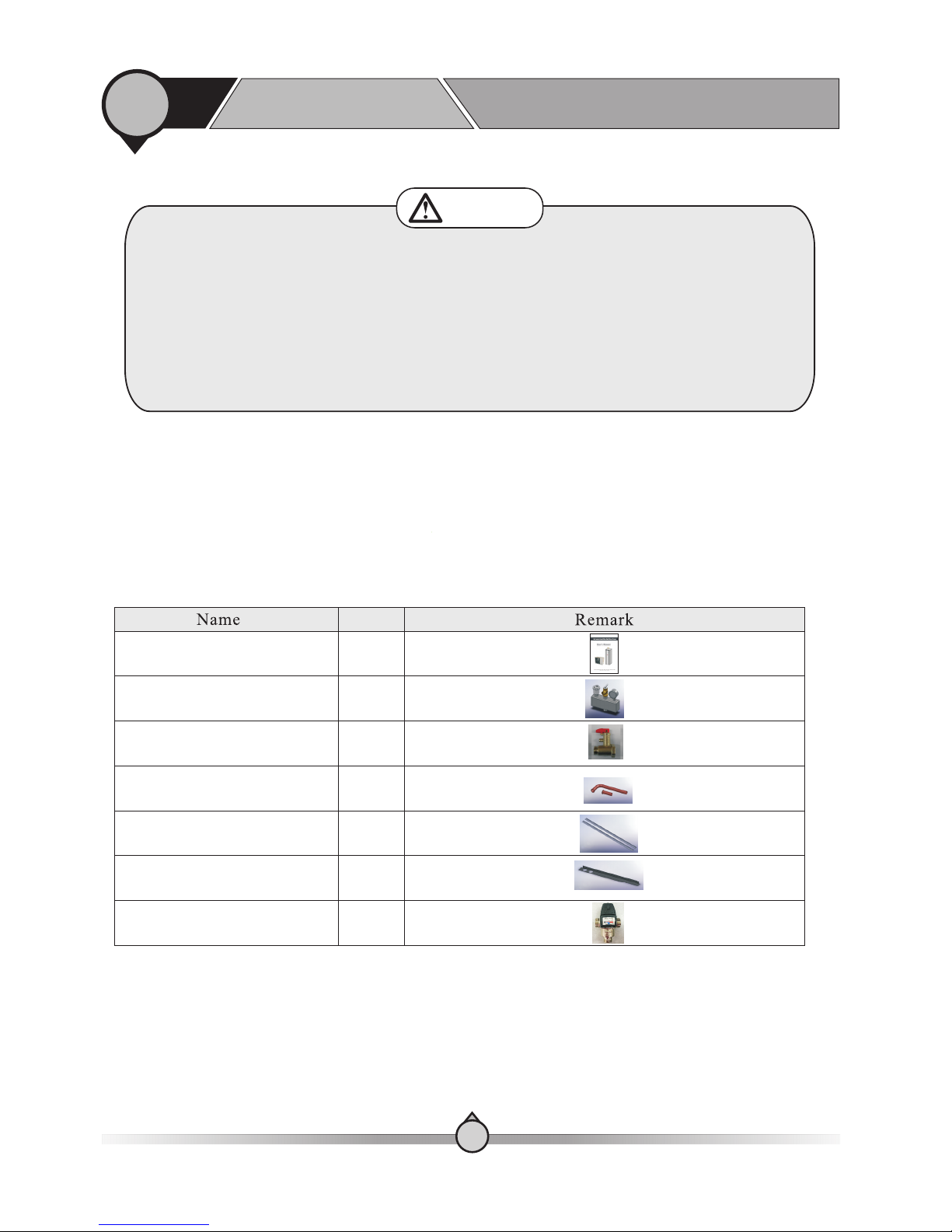
The accessories below are delivered together with the product .
Please check in time. If there is any shortage or damage, please contact local distributor.
【Indoor unit】
【 】List of accessories
1
1. List of accessories
Before use
1
04
User manual
Four-way Safety valve kit
Pressure release valve
Piping for mixture valve
Quantity
1pcs
1set
1pcs
1set
1pcs
2pcs
1pcs
L type decorative panel in
back side 2
Thermostat mixing valve
L type decorative panel in
back side 1
Attention
Dear Customer
Congratulation with your choice of heat pump. You have chosen a high quality product with
some of the latest technology within the heat pump market. This unit, will correctly installed
and set, provide you with cost efficient high level of comfort in your house regarding cooling,
heating and hot shower water.
Install and service the product with authorized and trained personnel only. Do not attend to do
the installation yourself, since the warranty of the product will not be valid. Please read this
manual carefully and make sure you follow the service and maintenance program to ensure
best lifetime and economy of the product. The longer the lifetime, the better investment.
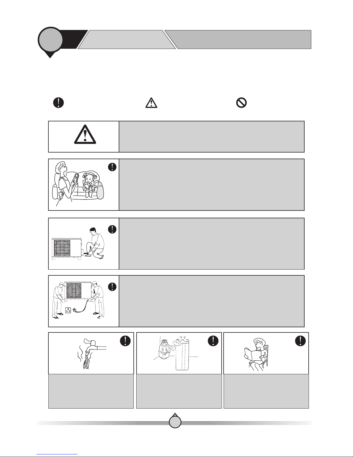
CautionWarning
Prohibition
which concerns the product and your personal safety.
The following symbols are very important. Please be sure to understand their meaning,
【 】Symbol description
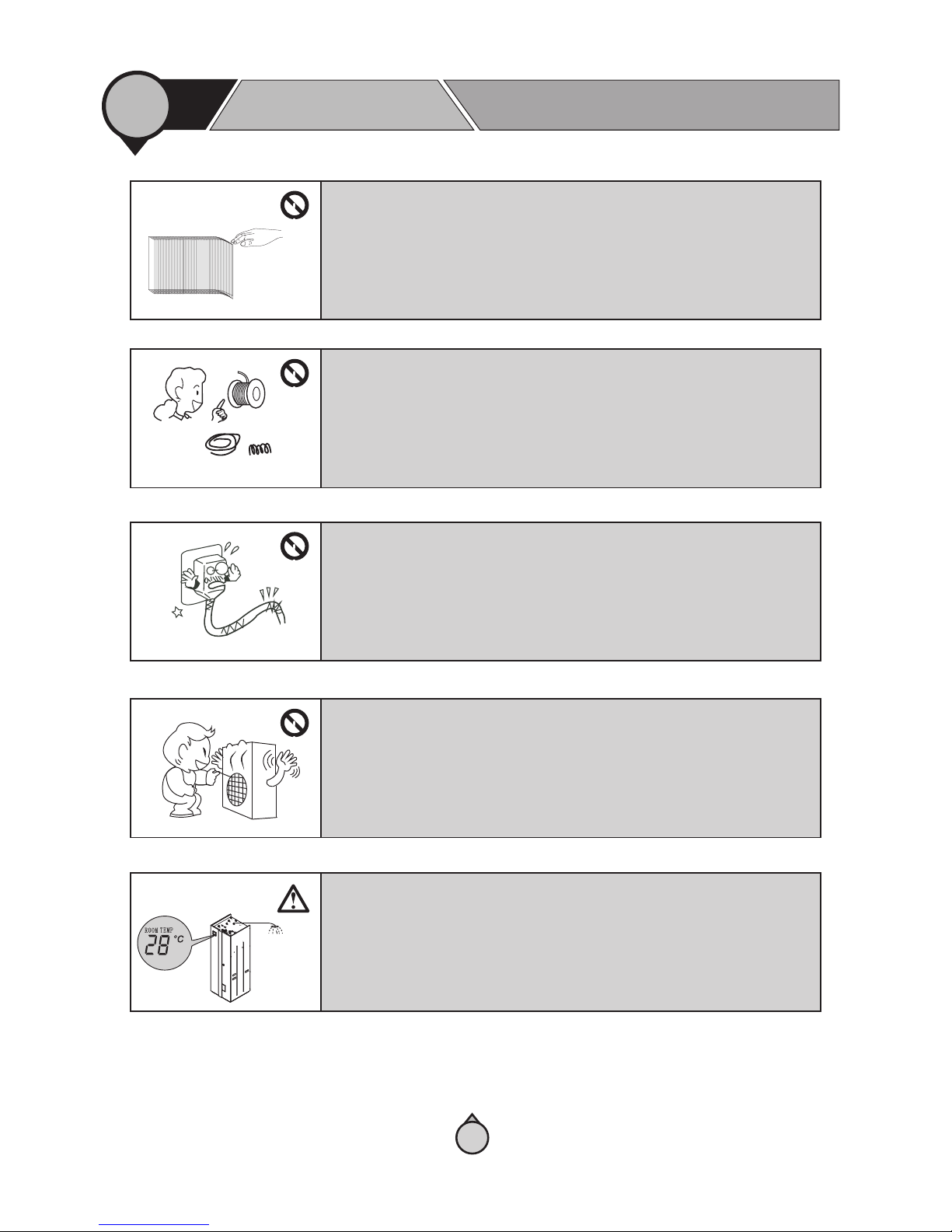
The installation, dismantlement and maintenance of the unit must be performed
by qualified personnel. It is forbidden to do any changes to the structure of the
unit. Otherwise injury of person or unit damage might happen.
【 】Safety precautions
Make sure the power supply to the heat pump unit is off before any operations are
done on the unit. When the power cord gets loose or is damaged, always get a
qualified person to fix it.
1
2. Safety precautions
Before use
1
05
User Man ual
Be sure to read this manual before
use.
Keep the unit away from the
combustible or corrosive environment.
Before taking shower, please always
add a mixture valve before water tap
and set it to proper temperature.
This appliance can be used by children aged from 8 yearsand above and persons
with reduced physical, sensory or mental capabilities or lack of experienceand
knowledge if they have been given supervisionor instruction concerninguse of the
appliance in asafeway and understand the hazards involved. Childrenshall not play
with the appliance. Cleaning and user maintenance shall not be made by children
without supervision.
1.The heat pump is for “Closed pressurized water borne systems only, with
running pressure from 1-2,5 bars”.
2. Heat pump indoor unit should only be placed in a room with drainage in the floor.
(If any catastrophic leak from the water tank, no costly damage to the house can be
put on ES).
Water tank
1
2. Safety precautions
Before use
1
06
Ground wire
Use a dedicated socket for this
unit,otherwise malfunction may
occur.
The power supply to the unit must
be grounded.
Don't ru n th e heat pump unit
with water t emperature lowe r
than 25℃.
Do not tou ch t he power plug with
wet hand s. Never pull out the pu lg
by pulling t he power cable.
Water or any kind of liquid is strictly
forbidden to be poured into the
product, or may cause creepage or
breakdown of the product.
When running the unit, never cover
the product with clothes, plastic
cloth or any other material that
block ventilation on the product,
which will lead to low efficiency or
even non-operation of this unit.
Main
Power Cable
RCD
Indoor
unit
It is mandatory to use a suitable circuit
breaker for the heat pump and make
sure the power supply to the heater
corresponds to the specifications.
Otherwise the unit might be damaged.
Disposal of Scrap Batteries --Please discard the batteries as sorted
municipal waste at the accessible
collection point.
Installation of a residual current device
(RCD) having a rated residual
operating current not exceeding
30 mA is advisable.
ON
OFF
City water inlet
Connect to water tank
Min. 0.1 Mpa
Max. 0.7 Mpa
The maximum inlet water pressure, in pascals: 0.7Mpa.
The minimum inlet water pressure, in pascals, if this is necessary for the correct operation of the appliance: 0.1Mpa.
Sanitary hot
water
1
2. Safety precautions
Before use
1
07
Be aware fin ger might be hurt by th e fin of the coil.
Coppe r
Steel
Fuse
Please s el ect the correct fus e or breaker as per rec ommended. Steel w ire or
copper w ir e cannot be taken as su bstitute for fuse o r breaker. Otherwise ,
damaged ma ybe caused.
When the power cord gets loose or is damaged, always get a qualified person to
fix it.
Do not touch the air outlet grill when fan motor is running.
Please mind that when the unit works under room temperature control mode, it
may not supply sanitary hot water with enough high temperature.
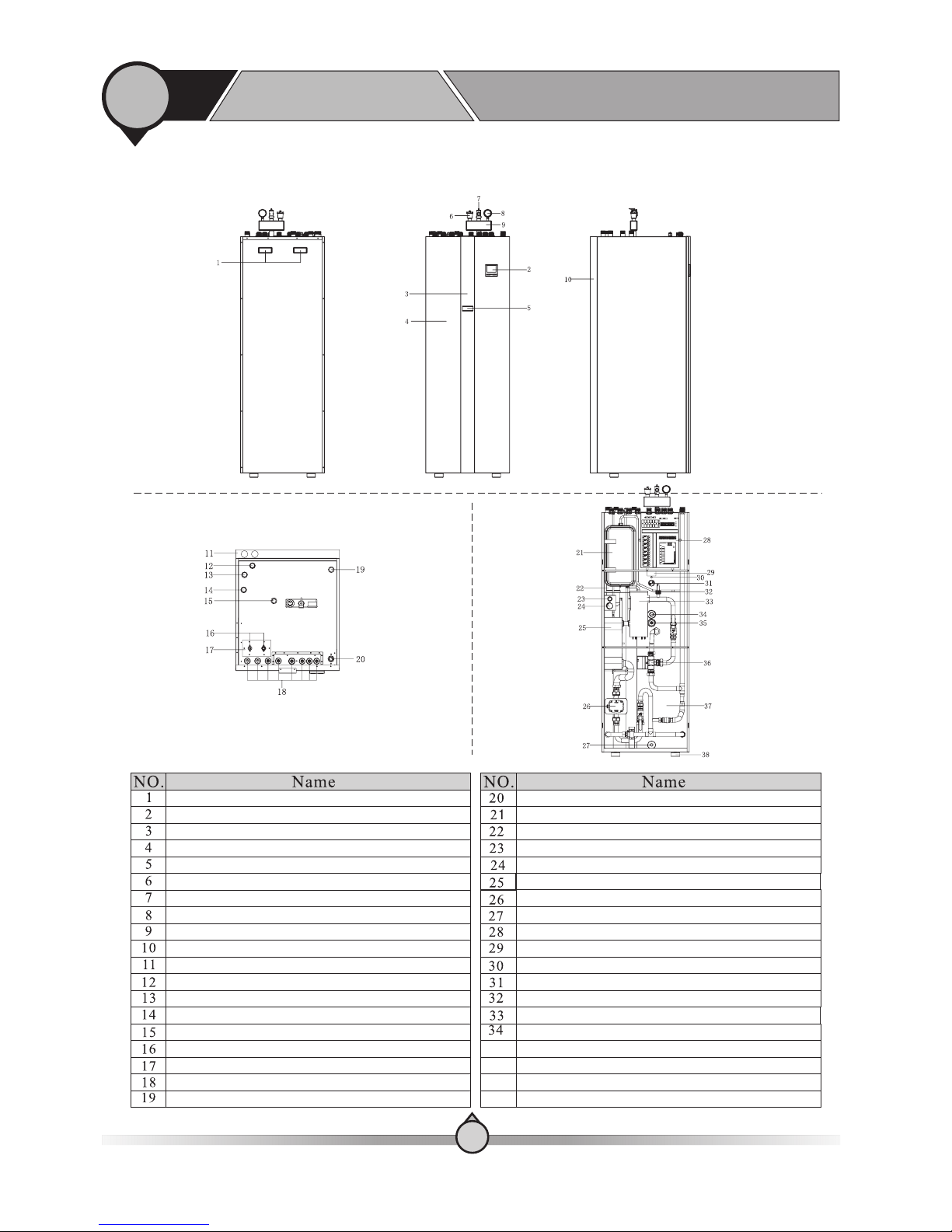
【 】 Indoor unit
Inside
Top
Outside
1
3. Main components
Before use
1
08
35
36
37
38
AWT9/11-V 5+
Handle
Wired controller
Decorative panel
Front panel
Digital thermostat
Automatic air purging valve
T/P valve
Water pressure gauge
Four-way safety valve kit
L type decorative panel in back side 1
L type decorative panel in back side 2
Middle temperature hot water outlet
Filling water to coil
Filling water to water tank
High temperature hot water outlet
Refrigerant connector(3/8’’~½’’)
Fixing plate for refrigerant connector
Cable gland
Water from heating/cooling system(G1’’male)
(G1’’male)
(G1’’male)
(G3/4’’male)
(G1’’male)
Water to heating/cooling system
Water expansion tank
Refrigerant expansion tank
Emergency Switch for 6KW electric heater
Thermostat knob
Plate heat exchanger
Water pump
Drainage
Electric box
Overheating protector for 1.5KW electric heater
Temperature sensor for 1.5KW electric heater
1.5KW electric heater 230V/50Hz/1Ph
Water flow switch
6KW electric heater 400V/50Hz/1Ph
Anode Rod
Temperature sensor for hot water mode
Motorized three-way valve
Water tank
Rubber absorber feet
(G1’’male)
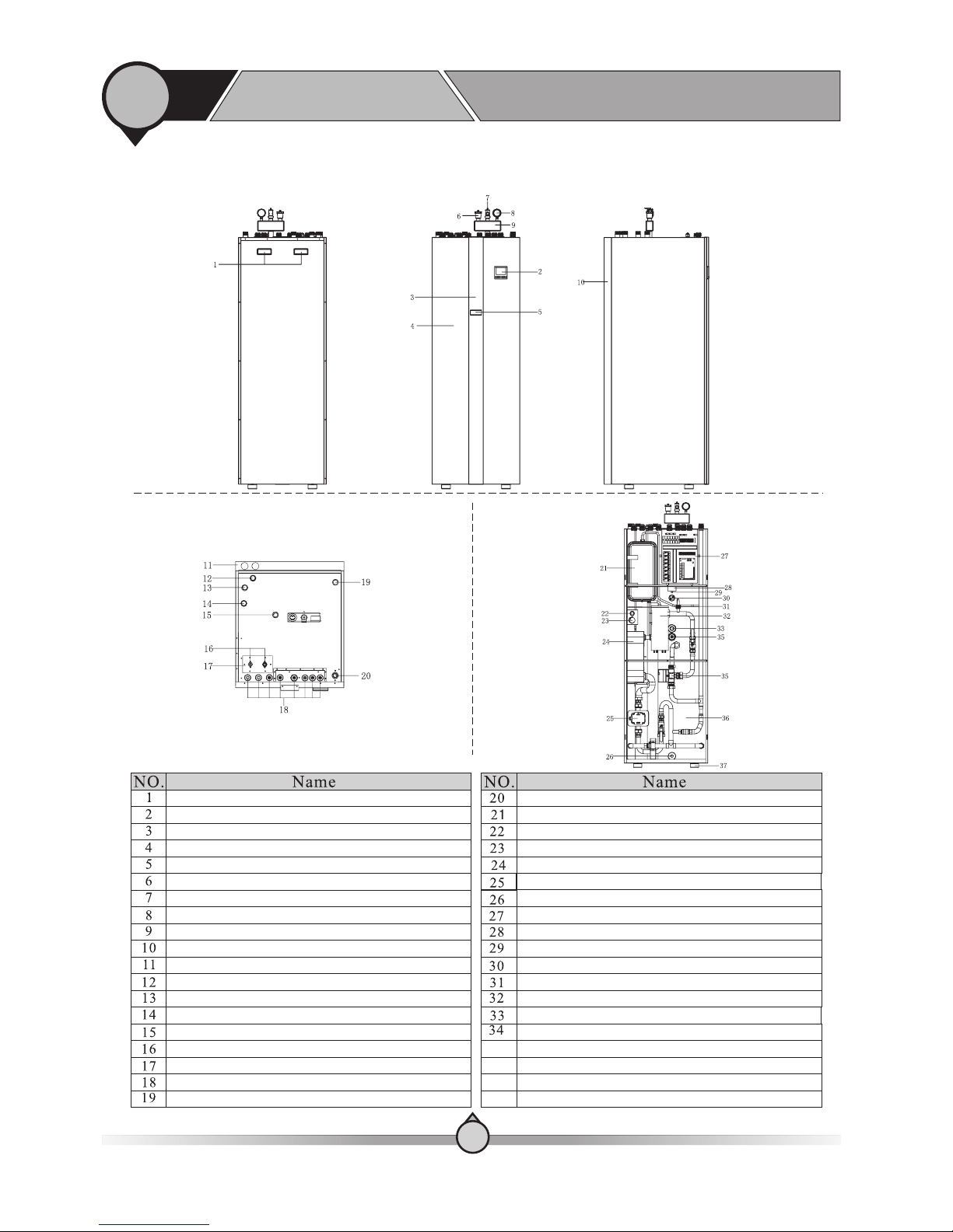
【 】 Indoor unit
Inside
Top
Outside
1
3. Main components
Before use
1
09
35
36
37
AWT13-V5+
Handle
Wired controller
Decorative panel
Front panel
Digital thermostat
Automatic air purging valve
T/P valve
Water pressure gauge
Four-way safety valve kit
L type decorative panel in back side 1
L type decorative panel in back side 2
Middle temperature hot water outlet
Filling water to coil
Filling water to water tank
High temperature hot water outlet
Refrigerant connector
Fixing plate for refrigerant connector
Cable gland
Water from heating/cooling system
(G1’’male)
(G1’’male)
(G3/4’’male)
(G1’’male)
(3/8’’~5/8’’)
(G1’’male)
Water to heating/cooling system
Water expansion tank
Emergency Switch for 6KW electric heater
Thermostat knob
Plate heat exchanger
Water pump
Drainage
Electric box
Overheating protector for 1.5KW electric heater
Temperature sensor for 1.5KW electric heater
1.5KW electric heater 230V/50Hz/1Ph
Water flow switch
6KW electric heater 400V/50Hz/1Ph
Anode Rod
Temperature sensor for hot water mode
Motorized three-way valve
Water tank
Rubber absorber feet
(G1’’male)
【 】 Indoor unit
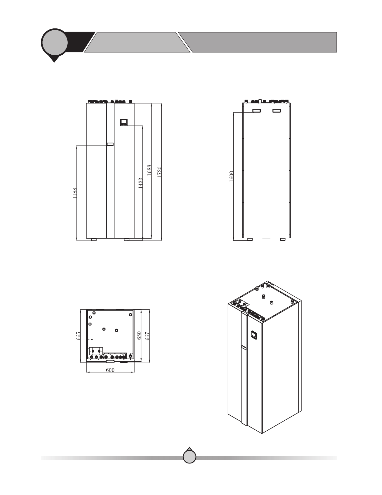
1
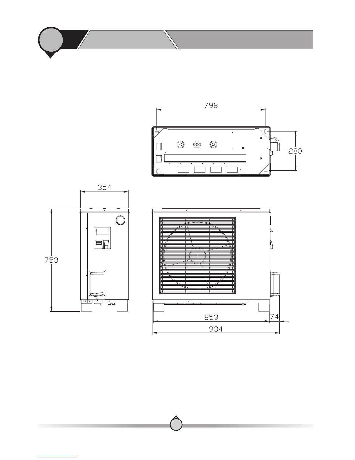
4. Outlines and dimensions
Before use
Unit:mm
1
10
AWT9/11/1 3-V5+
1
4. Outlines and dimensions
Before use
【 】 Outdoor unit
Unit:mm
1
11
AW9-V5+
Refrigerant connector
dimension:φ9.52&φ12.7
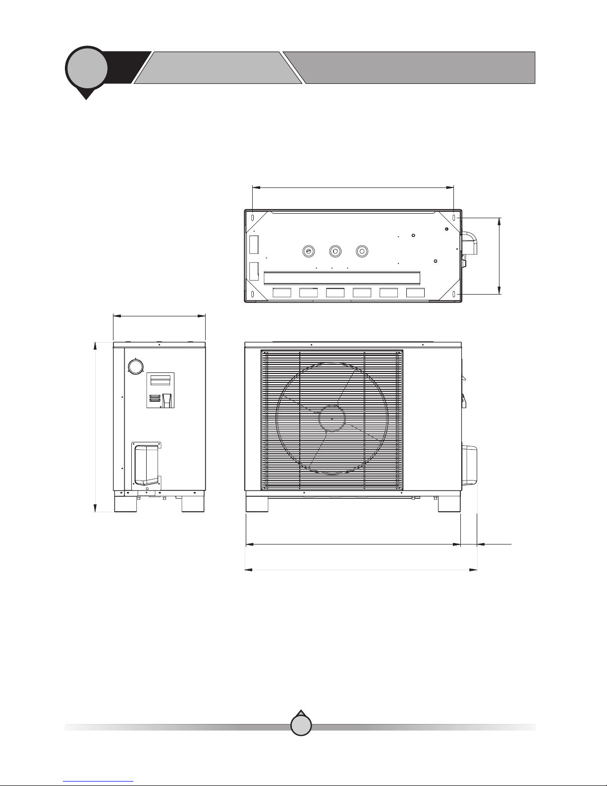
1
4. Outlines and dimensions
Before use
【 】 Outdoor unit
Unit:mm
1
12
Liquid pipe O.D. 9.52
Gas pipe O.D. 12.7
φ ( )
φ ( )
3/8”
1/2"
904
343
414
763
964
1044
74
AW11-V5+
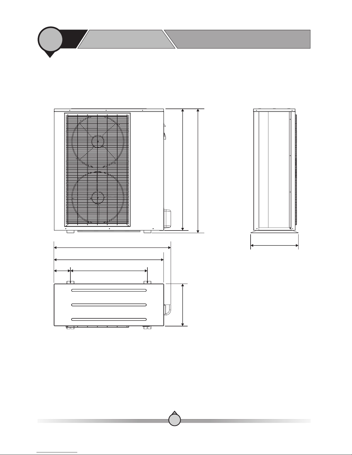
1
4. Outlines and dimensions
Before use
【 】 Outdoor unit
Unit:mm
1
13
AW13-V5+
Refrigerant connector
dimension:φ9.52&φ16
1195
1171407
740159
1058
1124
460
Outdoor Unit
Type
Water Pressure Drop
Rated Water Fl ow
Net Dimension
Packing Dimension
Net Weight
Gross Weight
Kpa
Inch
Piping Conn ec tion
3
m / h
Water ide Heat S
Exchanger
mm
mm
Kg
Kg
Model Number
Max. Water Temp.
℃
Tank Volume
L
Power supp ly a nd e lectric connections
Refrigeran t
Indoor Unit
Piping Kits
1
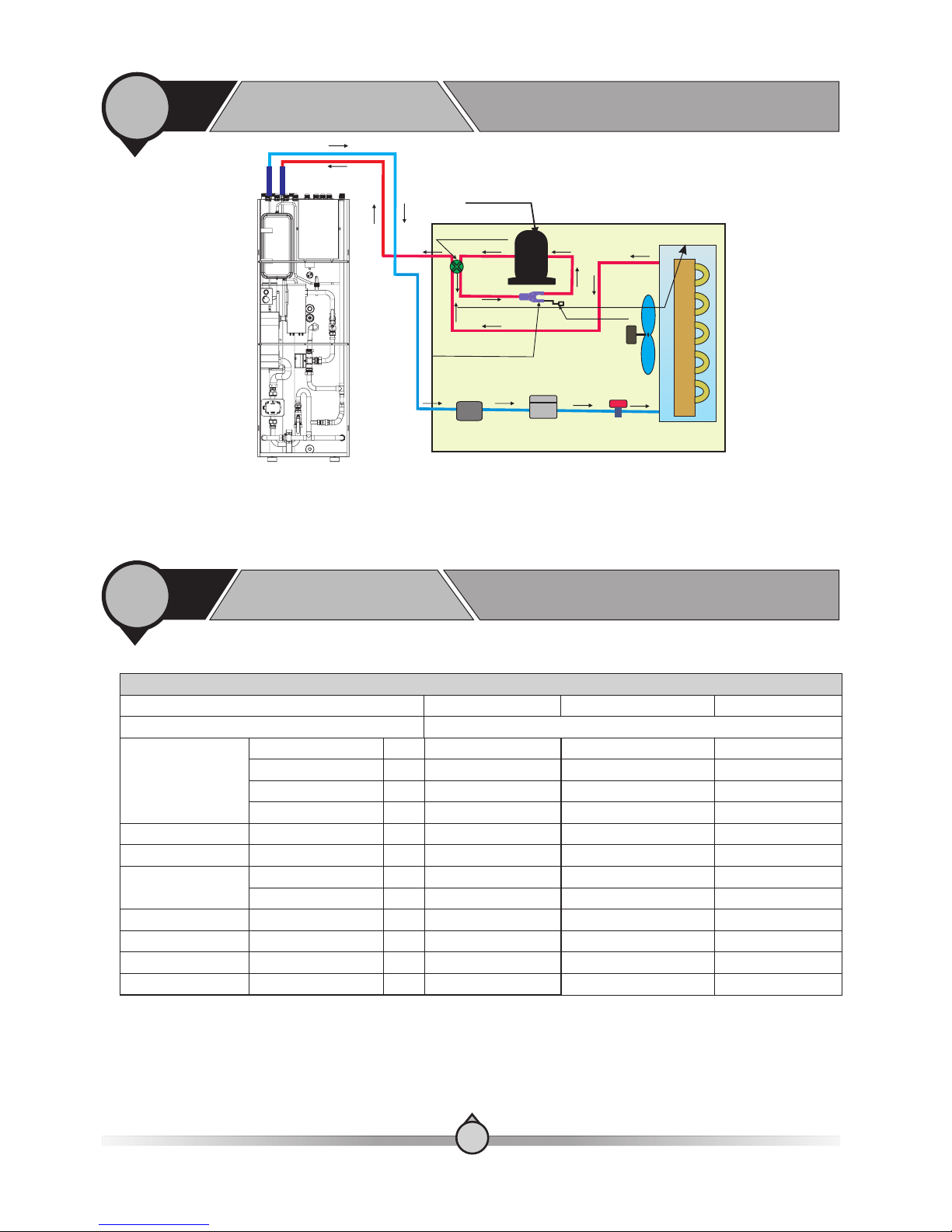
5. Working principles
Before use
Plate Heat Exchanger
Plate Heat Exchanger
Plate Heat Exchanger
30 3030
G1” G1”G1”
1.5 1.51 .5
600 650 1720× × 600 650 1720× ×600 650 1720× ×
638 708 1917× × 638 708 1917× ×638 708 1917× ×
AWT9 -V5+ AWT11-V5+ AWT1 3-V5+
75 7575
250L 250L250L
130 130 130
140 140 140
R410A R410AR410A
R410A R410AR410A
1
6. Specifications
Before use
1
14
Please check the chapter 2-9
Indoor unit
Expansion
Valve
Filter
Refrigerant
Three-Way Valve
Pressure Check
Valve
Power Supply
Compressor
Four-Way Vale
Fan Motor
Evaporator
1
6. Specifications
Before use
1
15
Outdoor Unit
Power Supply-Refrigerant
V/Hz/Ph
220-240/50/1- R410A
Max. Heating Capacity (1)
C.O.P (1)
Heating Capacity Min./Max.(1)
Heating Power Input Min./Max.(1)
C.O.P Min./Max.(1)
Max. Heating Capacity(2)
C.O.P (2)
Heating Capacity Min./Max.(2)
Heating power input Min./Max.(2)
C.O.P Min./Max.(2)
Max. Cooling Capacity(3)
E.E.R (3)
Cooling Capacity Min./Max.(3)
Cooling Power Input Min./Max.(3)
E.E.R Min./Max.(3)
Max. Cooling Capacity(4)
E.E.R(4)
Cooling Capacity Min./Max.(4)
Cooling Power Input Min./Max.(4)
E.E.R Min./Max.(4)
KW
W/W
KW
W
W/W
KW
W/W
KW
W
W/W
KW
W/W
KW
W
W/W
KW
W/W
KW
W
W/W
11.510.1
3.824.03
4.67/11.54.33/10.1
915/3029
975/2153
3.82/5.054.02/4.65
10.79.53
2.953.17
4.14/10.74.19/9.53
1218/3624
1230/2990
2.95/3.563.12/3.55
9.26.84
2.682.09
4.33/9.24.1/6.84
993/34651230/3280
2.68/4.112.09/3.32
6.745.05
2.151.58
2.17/6.742.34/5.05
924/31321080/3200
2.15/3.01.58/2.4
Compressor
Twin Rotary-1
Fan
Quantity
Airflow
Rated Power
m³/h
W
31003000
7676
11
Noise Level
Outdoor
Intdoor
DC Inverter Air to Water Heat Pump Unit
Water Pump
L
℃
Max Water Head
250
30-52 52 75℃- -
7.5
dB(A)
m
12.6
3.89
4.2/12.6
926/3072
3.89/4.77
11.5
3.08
3.76/11.5
1267/3723
2.97/3.28
10.3
3.29
4.29/10.37
957/3156
3.29/4.63
7.9
2.63
2.34/7.91
1000/3012
2.33/3.12
4200
150
59
2
Model no.
Type of Product
Type - Quantity/System
lnch
Water Side
Heat
Exchanger
Type
Water Pressure Drop
Piping Connection
Kpa
Plate Heat Exchanger
30
G1"
56
35
Water Volume
Range of setting temperature℃
AW9- V5+ AW11-V5+ AW13-V5+
1
6. Specifications
Before use
1
09
1
6. Specifications
Before use
1
16
NOTE:
(1) Heating condition: water in/out temperature:30℃/35℃, ambient temperature:DB/WB 7/6℃;
(2) Heating condition: water in/out temperature:40℃/45℃, ambient temperature:DB/WB 7/6℃;
(3) Cooling condition: water in/out temperature:23℃/18℃, ambient temperature:35℃;
(4) Cooling condition: water in/out temperature:12℃/7℃, ambient temperature:35℃.
(5) The specifications are subject to change without prior notice.
For actual specifications of the unit, please refer to the specification stickers on the unit.
Kg/h
inch
240 300 360
Hot water capacity*
Refrigerant pipe connection
inch
KW
KW
℃
Mpa
G1"
Water pipe connection
Inbuilt Electric Heater
Inbuilt Electric Heater
Range of working temperature
Max. Pressure of Water
Control of 2KW electric heater
Control of 6KW electric heater
- ~25 45
0.7
Manual
Auto/Manual
2(220-240V/50Hz/1PH)
6(400V/50Hz/3PH)
3/8 、″ 1/2″ 3/8 、″ 5/8″
Net Dimension
(L×D×H)
Packing Dimension
(L×D×H)
Net Weight
Shipping Weight
Outdoor Unit
Indoor Unit
Outdoor Unit
Indoor Unit
Outdoor Unit
Indoor Unit
Outdoor Unit
Indoor Unit
mm
mm
mm
mm
Kg
Kg
Kg
Kg
934×354×753
900×440×810
1044×414×763
1123×400×1195
600×650×1720
1130×500×815 1330×490×1330
638×708×1917
62.5
130
72.5
140
113
123
65
75
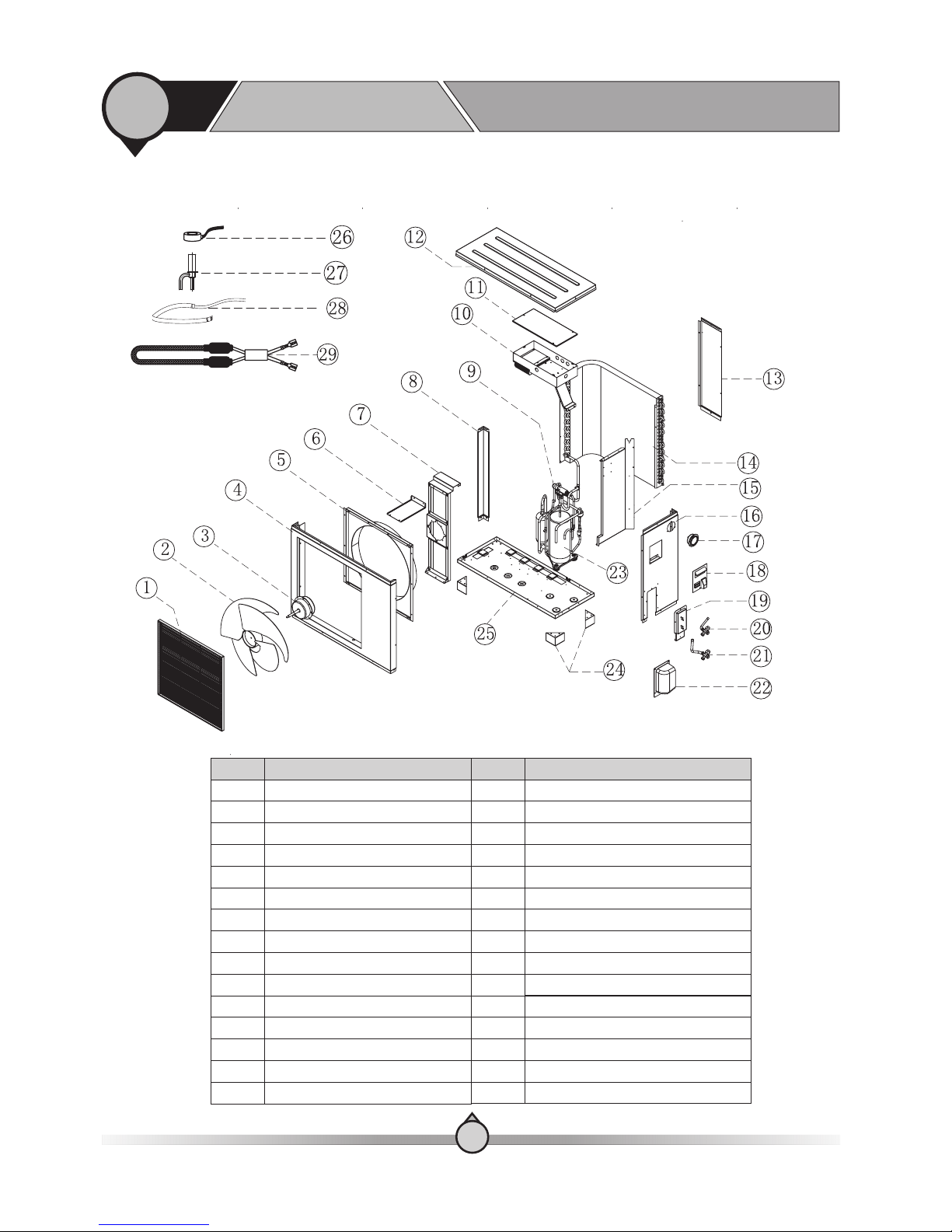
【 】 Indoor unit
1
7. Exploded view
Before use
1
17
AWT9/11-V 5+
Quantity
1
1
1
1
3
1
1
1
1
1
1
1
1
1
1
1
1
1
1
Emergency switch for 6KW electric heater
Refrigerant expansion tank
Part name
Mechanical thermostat
Overheating protector
1.5kw electric heater
Plate heat exchanger
6kW electric heater
6L expansion tank
Water flow switch
Three-way valve
Air purging valve
Wired controller
Front panel
Water pump
Indoor PCB
T/P valve
Manometer
Water tank
Relay
Item no.
1
2
3
4
5
6
7
8
9
10
11
12
13
14
15
16
17
18
19
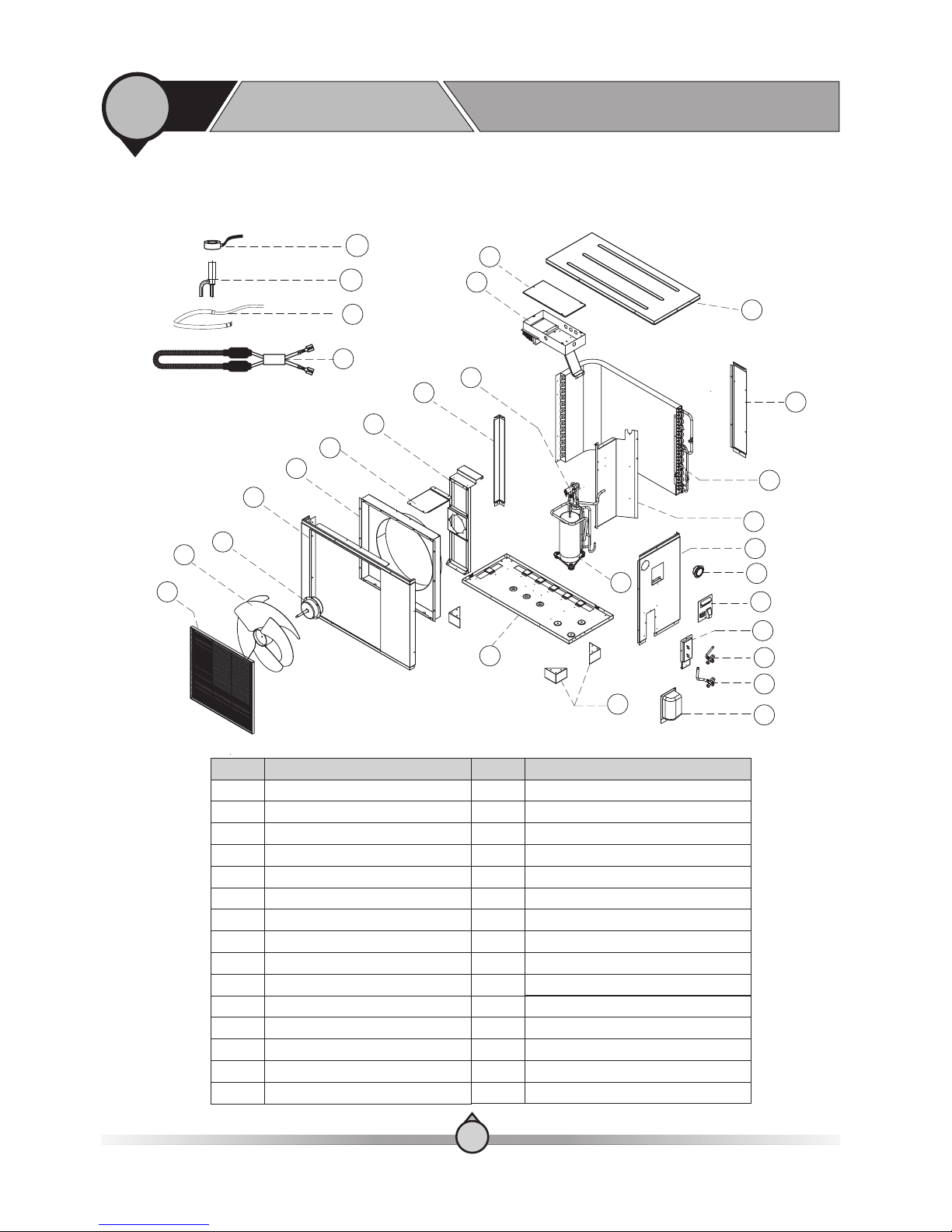
【 】 Indoor unit
1
7. Exploded view
Before use
1
AWT13-V5+
18
Item no. Part name
Quantity
1
2
3
4
5
6
7
8
9
10
11
12
13
14
15
16
17
18
1
1
1
1
3
1
1
1
1
1
1
1
1
1
1
1
1
1
Front panel
Wired controller
1.5kw electric heater
Mechanical thermostat
Overheating protector
Plate heat exchanger
6L expansion tank
6kW electric heater
Three-way valve
Water pump
Indoor PCB
Relay
Water flow switch
Emergency switch for 6KW electric heater
Air purging valve
T/P valve
Manometer
Water tank
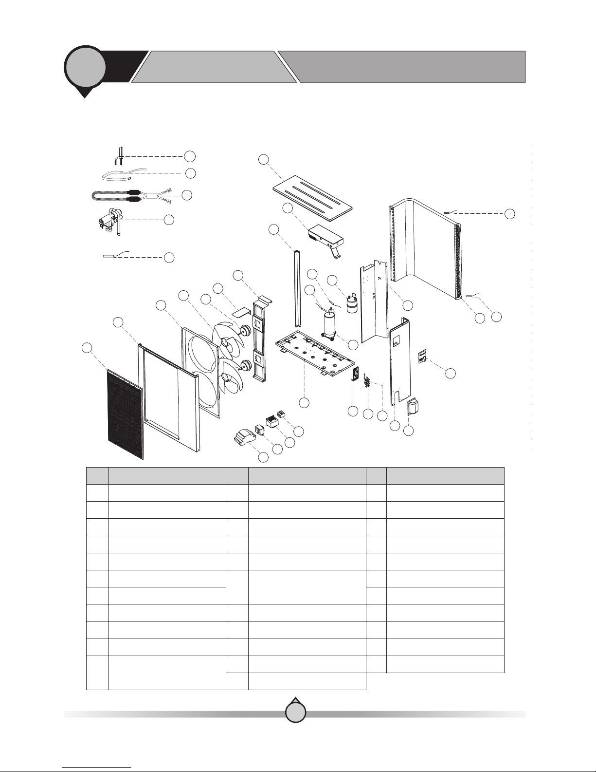
【 】 Outdoor unit
1
7. Exploded view
Before use
Compressor
Feet
EEV Coil
NO
Name
NO
Name
Outdoor Fan
Outdoor Motor
Front Panel
Air Guide
Fixture
Motor Bracket
Column Support
Four-Way Valve
Electrical Box
Decorative Panel
Top Panel
Electric Box Cover
Back Panel
Right Plate
Pressure
Big Handle
3/8 Valve
1/2 Valve
Valve Cover
Electrical Expansion Valve
Bulkhead
Bottom Plate
Condenser
Compressor Heater
Bulkhead
Condebser Heater
1
1
2
3
4
5
6
7
8
9
10
11
12
13
14
15
16
17
18
19
20
21
22
23
24
25
26
27
28
29
AW9-V5+
19
【 】 Outdoor unit
1
7. Exploded view
Before use
Compressor
Feet
EEV Coil
NO
Name
NO
Name
Outdoor Fan
Outdoor Motor
Front Panel
Air Guide
Fixture
Motor Bracket
Column Support
Four-Way Valve
Electrical Box
Decorative Panel
Top Panel
Electric Box Cover
Back Panel
Right Plate
Pressure
Big Handle
3/8 Valve
1/2 Valve
Valve Cover
Electrical Expansion Valve
Bulkhead
Bottom Plate
Condenser
Compressor Heater
Bulkhead
26
27
28
29
8
9
5
6
7
1
2
3
4
10
11
12
13
14
15
16
17
18
19
20
21
22
23
24
25
Condebser Heater
1
20
1
2
3
4
5
6
7
8
9
10
11
12
13
14
15
16
17
18
19
20
21
22
23
24
25
26
27
28
29
AW11-V5+
【 】 Outdoor unit
1
7. Exploded view
Before use
1
AW13-V5+
1
2
3
4
6
7
8
9
10
5
12
13
14
15
18
11
16
17
19
20
21
22
23
24
11
29
30
32
31
33
25
26
27
28
13
NO
Name
NO
Name
Decorative panel
Name
NO
14
15
16
17
18
19
20
21
25
26
27
28
29
30
NO NO
Fixture
Front panel
Outdoor fan
Motor bracket
Column support
Controller
Outdoor motor
Air guide
31
32
1
2
3
4
5
6
7
8
9
Top panel
Coil and ambient
temperature sensor
Condenser
10
11
12
22
33
Bulkhead
Compressor
Handle
Suction temperature sensor
Bottom plate
Valve plate
5/8” Valve
Compressor discharge
temperature sensor
Sperator
3/8” Valve
Terminal block
Crankcase heater
PFC transducer
EEV controller
Condenser heater
4-Way valve
Electronic expansion valve
Transformer
EEV temperature sensor
23
24
Side panel
Valve cover
21

【Installation methods】
Sanitary hot water, floor heating hot water and radiator heating hot water can all be get from the
indoor unit. With its inbuilt 1.5kW and 6kW electric heater, it ensures its heating capacity in cold
days and guarantees enough high temperature sanitary hot water.
By using a mixture water to mix high temperature sanitary hot water and medium temperature
sanitary hot water together, it ensures the ideal temperature of sanitary hot water, as well as
increases the amount of sanitary hot water.
2
1. Installation methods
Installation
1
22
Ambient temperature: ℃ to
Media temperature: + ℃ to ℃
0 40
0 95
℃
【 】In the storage environment temperature range

2
1. Installation methods
Installation
1
23
【Installation
methods】
In the following pages you will find how to connect different system applications to this heat
pump, based on your system design. It is of course many ways to do this and it is impossible
tocover every possible system design in the market. We therefore use the following as our
standard applications that is safe, workable and that we recommend. Other applications and
settings for this is possible, but we leave this design to the installer, according to his knowledgeand
understanding of this specific unit menu and possible settings. It is some basic specifications
that applies for all system drawings which is highlighted, and that we ask you read carefully when
considering which system application to use.
-Sensor locations
-System with or without buffer tank
-Internal and external water pump
Sensor locations applies differently for different applications. As a general standard, please refer
to the following.
Sensor locations applies differently for different applications. As a general standard,
please refer to the following.
Without buffer tank: For more stable running of the heat pump, we suggest to place the
sensors on the return line and adjust the heating curve or cooling
temperature accordingly, to fit the normal Delta T for your heating/
cooling system.
With buffer tank(s): For more stable running of the heat pump, we suggest to place the
sensors in the buffer tank(s). As general standard, you should place the
heating sensor in the upper part and cooling sensor in the lower part.
Circulation pump: This unit has a built in circulation pump that makes it possible to
connect the unit directly to a heating system using the internal
circulation pump to circulate the water in the heating system. For bigger
system or in systems with too big pressure drop, the capacity of the
internal water pump is not enough, and a secondary water pump for the
system is required. An external water pump can be controlled by the
heat pump. Please refer to the following pages for different system
applications.
Observe! It is always the installer's responsibility to control that the pressure drop in the
heating system is not higher than the internal circulation pump can handle.
2
1. Installation methods
Installation
1
【1.Directly to heating system
】
【2.Directly to heating system
】
Observe! thermostatic controlled heating systems like floor heating,For radiators or fan
coils, an external bypass between turn and return manifold or thermostat valve, is
required.Minimum 28 mm copper piping or similar is required for heating system.
Observe! When external circulation pump is installed it must be connected to and powered
by the unit internal PCB
-No shunt valve
-No external circulation pump
-Internal bypass should be closed
-No shunt valve
-No external circulation pump for heating system installed
-Internal bypass should be closed -, and be partly in open position to balance the pressure
drop in the heating system.
. Thermostat controlled systems needs bypass in application 1.
24
Minimum 28 mm copper piping or similar is required for heating system.
2
1. Installation methods
Installation
1
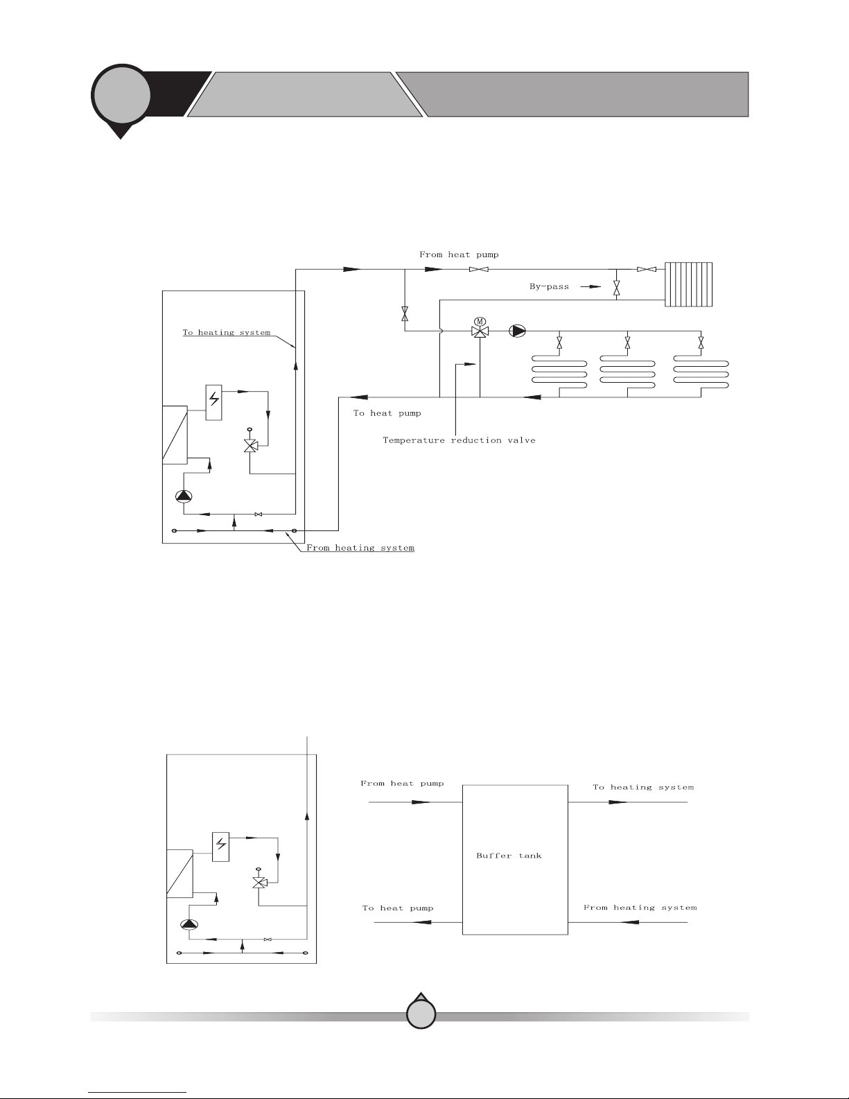
【3.Connected directly to combined high and low temperature heating system.
】
【4.Connected to a buffer tank
】
Observe! Temperature reduction valve and separate circulation pump for low temperature
heating system is required.Minimum 28 mm copper piping or similar is required for heating
system.
-Close the internal bypass
-External circulation pump is required
-Internal bypass closed.
-Optional power to external circulation pump
-Parameter in the menu “Heating buffer tank” and/or “cooling buffer tank” in “Group 0” of
advanced setting should be set to “1” = “with buffer tank”.
Minimum 28 mm copper piping or similar is required for heating system.
25
2
1. Installation methods
Installation
1
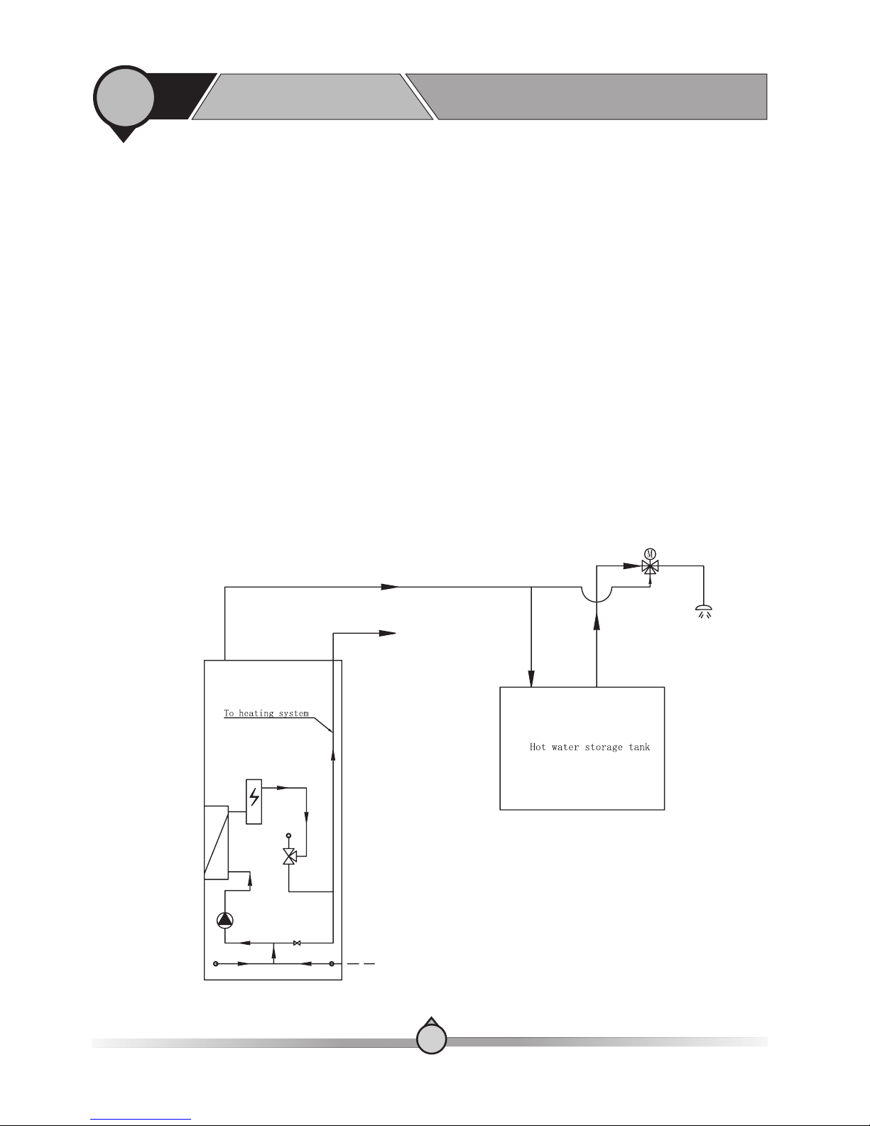
【5.Connecting external hot water heater.
】
Observe! This set up requires that the external water heater have its own heater with
thermostat control and a mixing valve on the outlet to your hot water supply lines. The
units mixing valve is not required, but will increase the efficiency.Minimum 28 mm copper
piping or similar is required for heating system.
-Reconnect the thermostatic valve on top of the unit so “hot water” from the unit is put to the
“cold” side of the mixing valve.
-“Plug” the medium hot water outlet
-Connect a bypass from units “hot water” outlet to the “coldwater” inlet on the external water
heater. Set the internal electronic hot water heater thermostat to 0
This unit have internal 250-liter water tank preserved for hot water for a normal family usage.
Some households use more hot water than normal, due to for example big bathtubs or the
number of family members. If so, we recommend connecting an extra water heater tank in series
with the heat pump hot water tank.
Heat pump will now either mix between heat pump and electric water heater or preheat the hot
water to the external water heater.
26
2
1. Installation methods
Installation
1
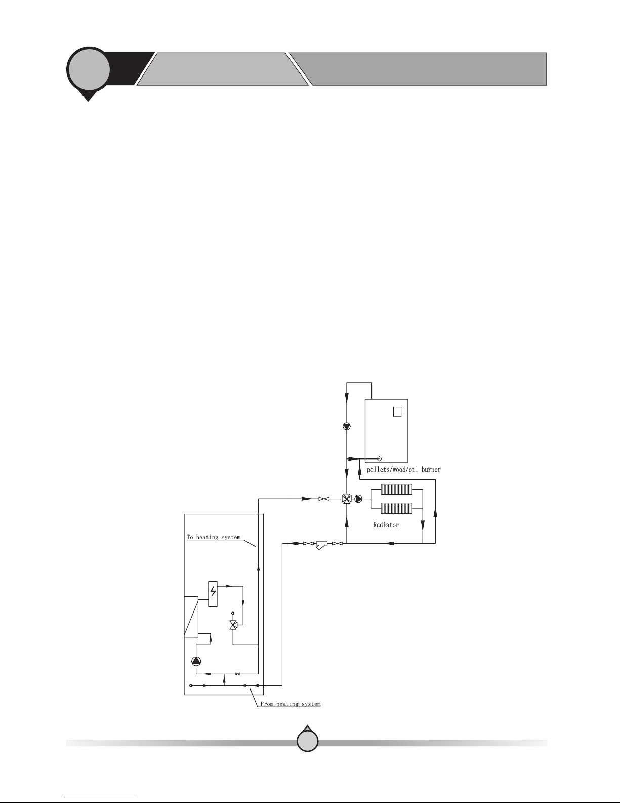
【6.Connecting an existing external boiler or other heating device as back up.
】
Observe! The installer must fulfill the installation and system design in accordance to both
functionality of heat pump and heating system, and in accordance to, local laws and
installation standards and regulations. A separate shunt valve with external controller is
required to mix in the heat from the boiler.Minimum 28 mm copper piping or similar is
required for heating system.
This unit is designed to be a total heating source for a normal house within a normal outdoor
temperature range. The heat pump has its own output and an additional built in 2 step 6 kW
(3+3 kW) electric heater for taking care of the peak load of your heating system the coldest days,
or if heat pump have functional failure. In some cases, the local lowest ambient temperatures or
the maximum heat load in the building is higher than the available output from the unit. For
some houses, the available electric power may not be enough to cover the input to the built in
electric heater. In these cases, you can connect an existing gas, oil or pellets burner to the system.
It is several ways to do this, so please use the below drawings as a template for how to design the
system. The heat pump can also control the start and stop of two external boiler or heating device
based on heat demand and prioritize between them, but external boiler or heating device always
needs to have its own internal temperature control and safety device.
27
2
1. Installation methods
Installation
1
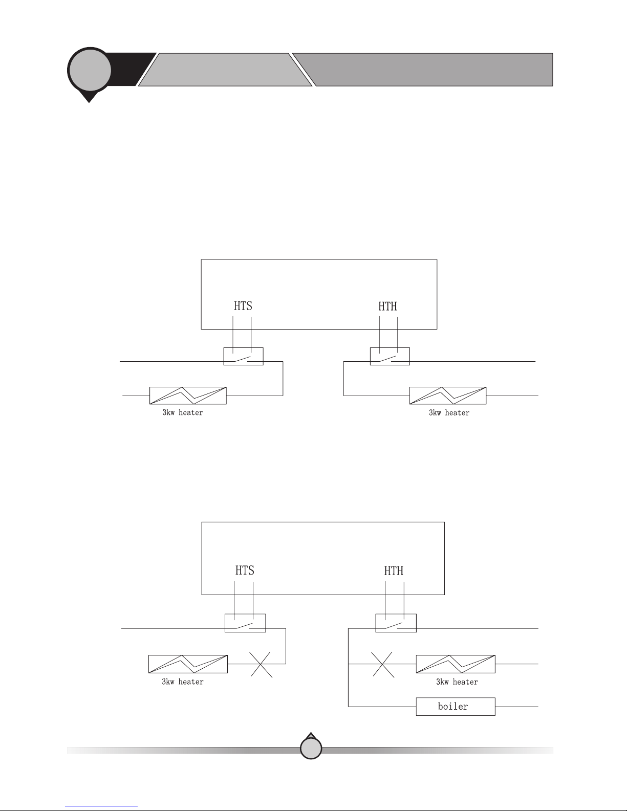
【6.1Control start of external boiler
】
6.1.1: If the available electricity is enough to over the power consumption of heat pump
only only:
Observe! HTH only valid when parameter setting C7 in Advanced Setting Group C to 1
(default factory setting).Minimum 28 mm copper piping or similar is required for heating
system.
HTS: 3kW auxiliary heater valid for both heating and domestic hot water operation
HTH: 3kW back-up heater for heating operation only
Default setting: HTH has higher priority than HTS, which means, HTS will be activated only
after HTH is activated, if heating capacity is not enough. Installer can choose from following
ways to add a boiler to the system:
-Leave the 3kW heater connected to HTS and HTH not connected with power supply.
-have boiler parallel connected to HTH port, so boiler will be activated if unit capacity is not
enough to cover the house heating demand.
28
 Loading...