

Effer DMU 2000, DMU 3000 PLUS, DMU 3000 Technical Assistance Manual
THE POWER OF PERFORMANCE
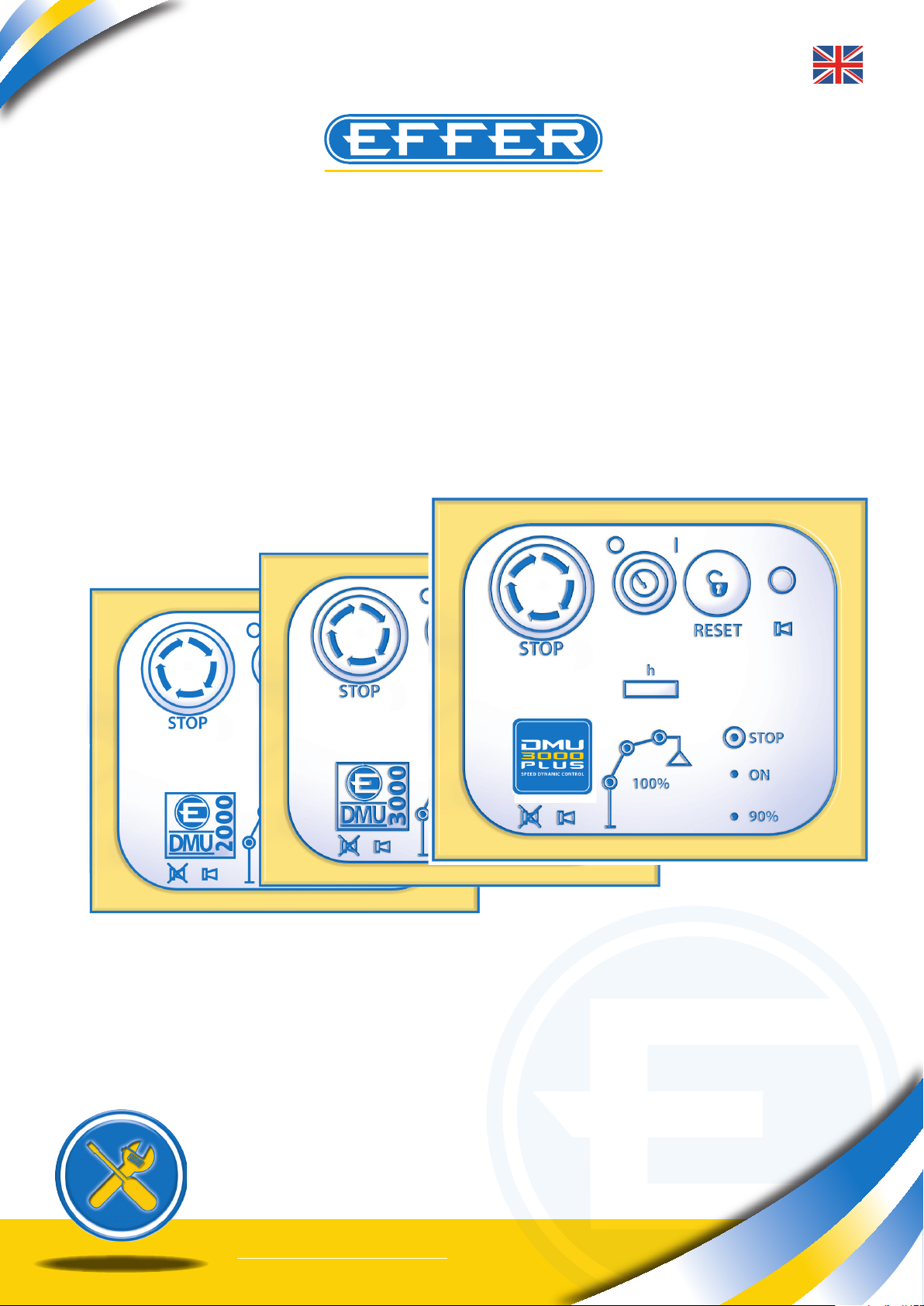
DATA MONITOR UNIT
DMU
3000
DMU
2000
DMU
3000 PLUS
ASSISTANCE MANUAL
Cod.: MI00002GB_4 - 14/02/09
DMU Suite 1.3
TECHNICAL
essebi - bo -
THE POWER OF PERFORMANCE
Electronic device DMU2000 - DMU3000 - DMU3000 PLUS
Electronic device DMU2000 - DMU3000 - DMU3000 PLUS
The purpose of this manual is to provide all the workshops that are part of the assistance network
of EFFER cranes with instructions for the use of the new software to run DMU2000, DMU3000
and DMU3000PLUS.
NOTE: The first version of load electronic control system fitted to EFFER cranes is called DMU
2000. Subsequently, all the electrical wiring was redesigned, different electrical components
were used and the logic to check crane boom uplifting was introduced. The system was named
DMU 3000.
At the end of the year 2007 the DMU 3000 PLUS was designed and installed as a standard feature on some crane models. This electronic system, unlike the previous ones, also runs the crane
maximum operating speed allowed according to load applied to the hook and the geometric
configurations which the crane has when working.
Please note that with the interface software DMU Suite 1.3 you can connect all types of DMU devices mentioned above, to edit the preset parameters or diagnostic operations.
To use the program “DMU Suite 1.3” you need a computer with the following minimum system
requirements:
- PC with Pentium 100 MHz processor
- CD-ROM drive
- Microsoft Windows operating system 98 or a more recent version
- Ram 32 MB (64 MB recommended)
- 100 MB of free space on hard disk
- Video card that supports a 800x600 monitor resolution or higher
- Monitor (laptops) 13’’ or higher
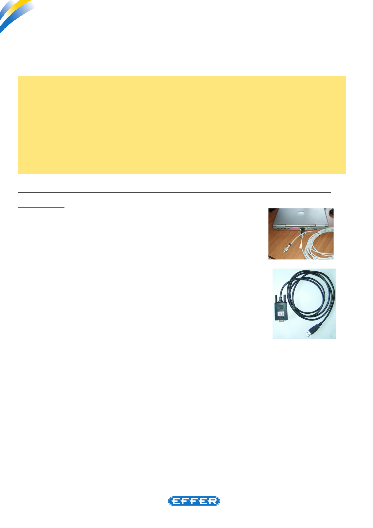
- n. 1 Standard free serial port (see p. 8 for more information)
In addition, it requires:
- n. 1 electrical cable for PC connection to DMU (code 9395261 l=10 M)
The following optional items may be supplied:
- n. 1 USB serial port adapter (code 9395668)
The software must be installed on your PC hard disk (portable computer recommended); it is not possible to start the programme directly from the CD-ROM.
2
Sol.Ge S.p.A. - 40013 Castel Maggiore (Bologna) - Italy
Via Bonazzi, 12/14 - Ph. + 39_(0)51_4181211 - Fax + 39_(0)51_701492
www.effer.it - e-mail: info@effer.it

Electronic device DMU2000 - DMU3000 - DMU3000 PLUS
THE POWER OF PERFORMANCE
DMU
3000
P L U S
SP EED DYN AMIC CO NTR OL
INDEX
1. Introduction
2. Glossary of terms used in the manual
3. Installing the software in the computer
4. Connecting the computer to crane
5. Using the software
6. Instructions for communication port setting
7. Explanation of various changeable parameters
8. Displaying/changing available data in the software
9. Printing DMU setting data
10. Instructions for diagnostics
11. Adjusting angle sensors fitted to booms
12. Instructions to change “anti-bridge height” intervention point -optional
13. Entering new parameters
14. Overload test
15. Quick Turning Off the “Pin” code
16. DMU diagnostics - Trouble shooting
3

THE POWER OF PERFORMANCE
Electronic device DMU2000 - DMU3000 - DMU3000 PLUS
Electronic device DMU2000 - DMU3000 - DMU3000 PLUS
1. Introduction
The software DMU Suite 1.3 is a software that should be preferably installed on a portable computer.
The software DMU Suite 1.3 allows managing/changing some of the parameters of the device. These
parameters are dened by LEVEL 1, that is available only to Sol.Ge S.p.A. autorized workshops, by entering the correct password.
A special electrical cable is required to connect the crane to the computer. This cable is supplied by Sol.
Ge with the software to install on your computer.
It is possible to run the software only after typing a password. In this way it is always possible to nd the
operator that has carried out changes/variation in standard setting parameters.
The password has a deadline: before the date of expiry the new password is communicated only to
workshops with which cooperation is established.
N.B.: If an expired password is typed in even by mistake to have access to the software, the software is automatically stopped. In order to use the software again it is necessary to perform a
new complete installation of the software on your computer.
NOTE: the DMU 3000 PLUS, unlike the other two types, also runs the radio control speed.
Please note that when the crane is tted with DMU 3000 PLUS the operating speeds are not
editable with the software, but it requires an authorization called LEVEL 2 which is reserved for
EFFER technicians.
2. Glossary of terms used in the manual
- DESKTOP : Screen that appears after starting the computer
- ICON : When selecting this image an action follows.
- MOUSE : Tool to move the cursor and to start an action.
- CURSOR: This indicator is on the display and is moved using the mouse.
- LAYOUT : Drawing showing the project.
- TO CLICK : Place the cursor on the required icon and press the left-hand button on the
mouse.
- DOUBLE CLICK: Press the left-hand button on the mouse quickly twice.
- DMU: Equipment fitted to cranes; electronic load limiting device
4

Electronic device DMU2000 - DMU3000 - DMU3000 PLUS
THE POWER OF PERFORMANCE
3. Installing the software in the computer
Please nd below the various steps required for software installation:
A - Insert the CD in the computer.
B - Click: “DMU INSTALL......”
C - Installation on the PC is automatically run by clicking “Next” every time it is requested, and
nally click “End”.
D - To start the program, just double-click the icon that automatically appears on computer
desktop.
Software startup requires 5-10 sec. according to the features of your computer.
E- On a dialog box, select a language with which you wish to dialogue with the software
(see section 5.)
F - After setting the language, an identical dialog box will ask for the password to access the
software.
NOTE: After installing the software on your computer, you can edit the setting parameters, or pro-
ceed to troubleshooting steps.
In order to complete software installation, we recommend you create a folder on your hard disk C of
your computer, inside the software folder, called - necessarily - “DMU2000Library” and dedicated to
the archive of the setting files that can be sent to you if you need to carry out updates to the crane:
in this specific case, the crane DMU will automatically connect to that folder, and from there you can
select the correct file to be sent to DMU.
5
THE POWER OF PERFORMANCE
Electronic device DMU2000 - DMU3000 - DMU3000 PLUS
Electronic device DMU2000 - DMU3000 - DMU3000 PLUS
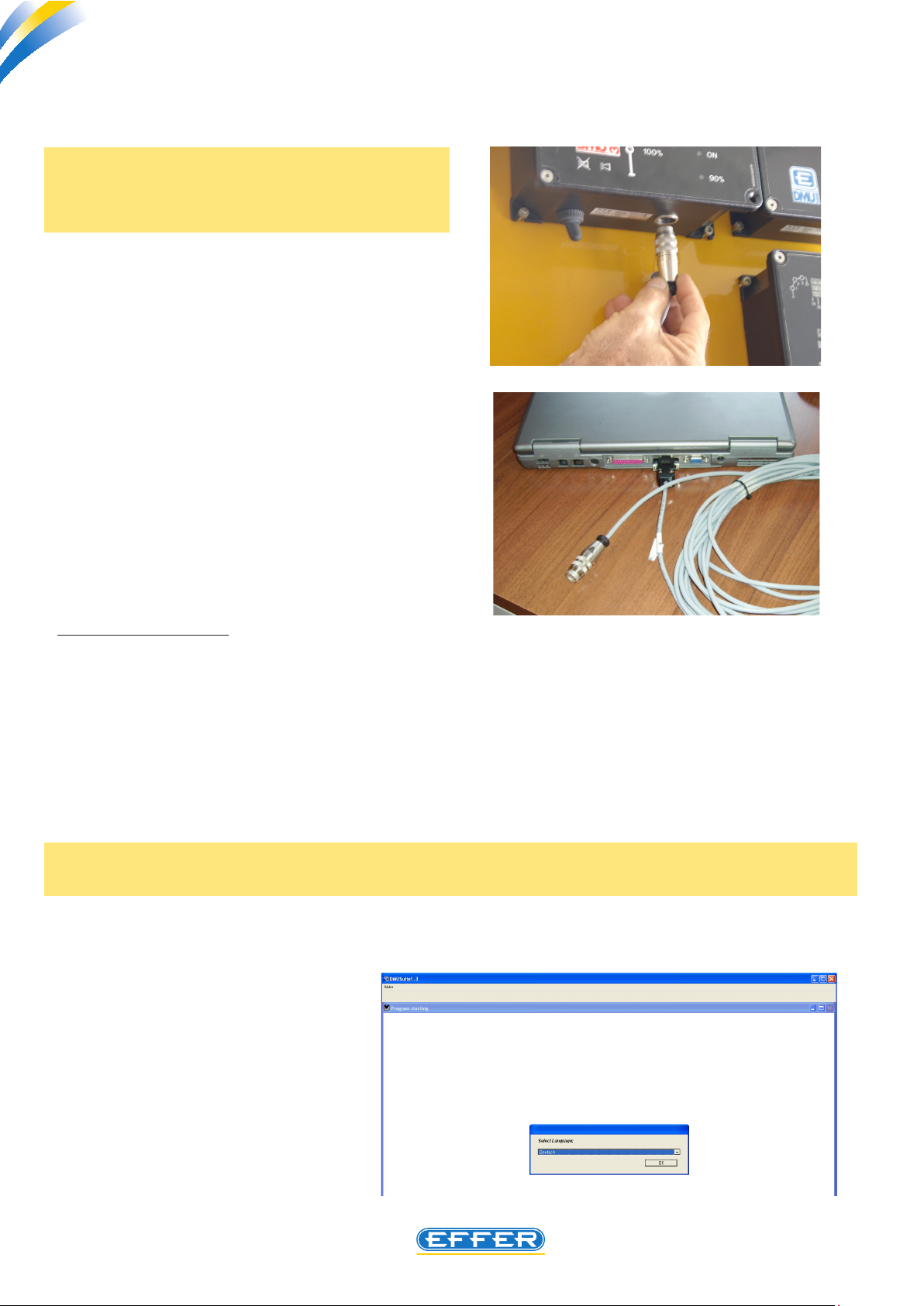
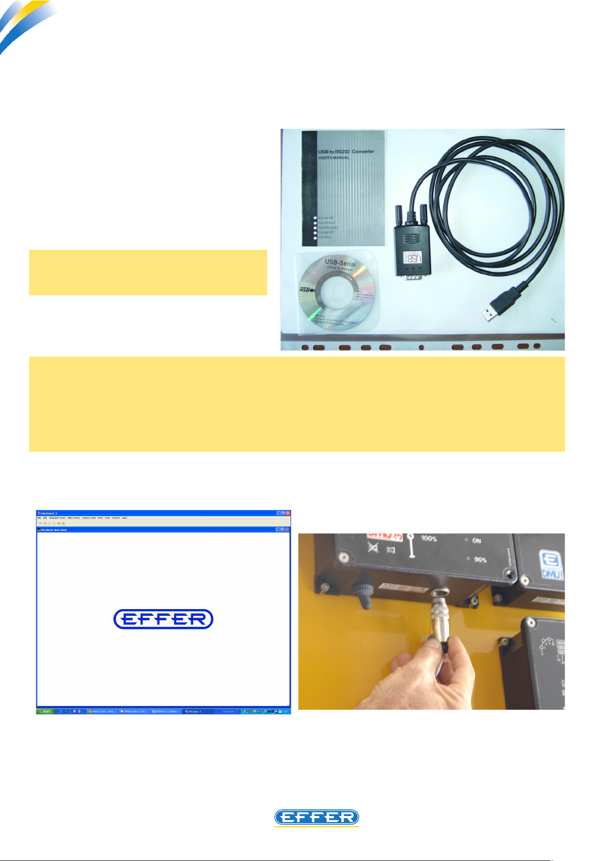
4. Connecting the computer to crane
N.B.: Cable connection between the DMU and
the PC must be done when DMU is off, and
when software is not running.
u Connect the programming cable between
DMU equipment installed on the crane and the
PC.
u Arrange the remote control- when tted
– next to the crane.
5. Using the software
a) Software startup
After connecting the computer to cranes as described in section 4, you can proceed to the activities
permitted by the software, following the instructions below:
u Turn on the DMU and enable the remote control (if tted)
u Double-click the icon “DMU Suite 1.3” on the computer desktop to run the software.
- The software is ready to be used.
Note: When using the software for the rst time, a window “Select Language” appears.
u Select the dialogue language and CLICK OK
Then the software will always display
the last language selection.
6
Electronic device DMU2000 - DMU3000 - DMU3000 PLUS
THE POWER OF PERFORMANCE
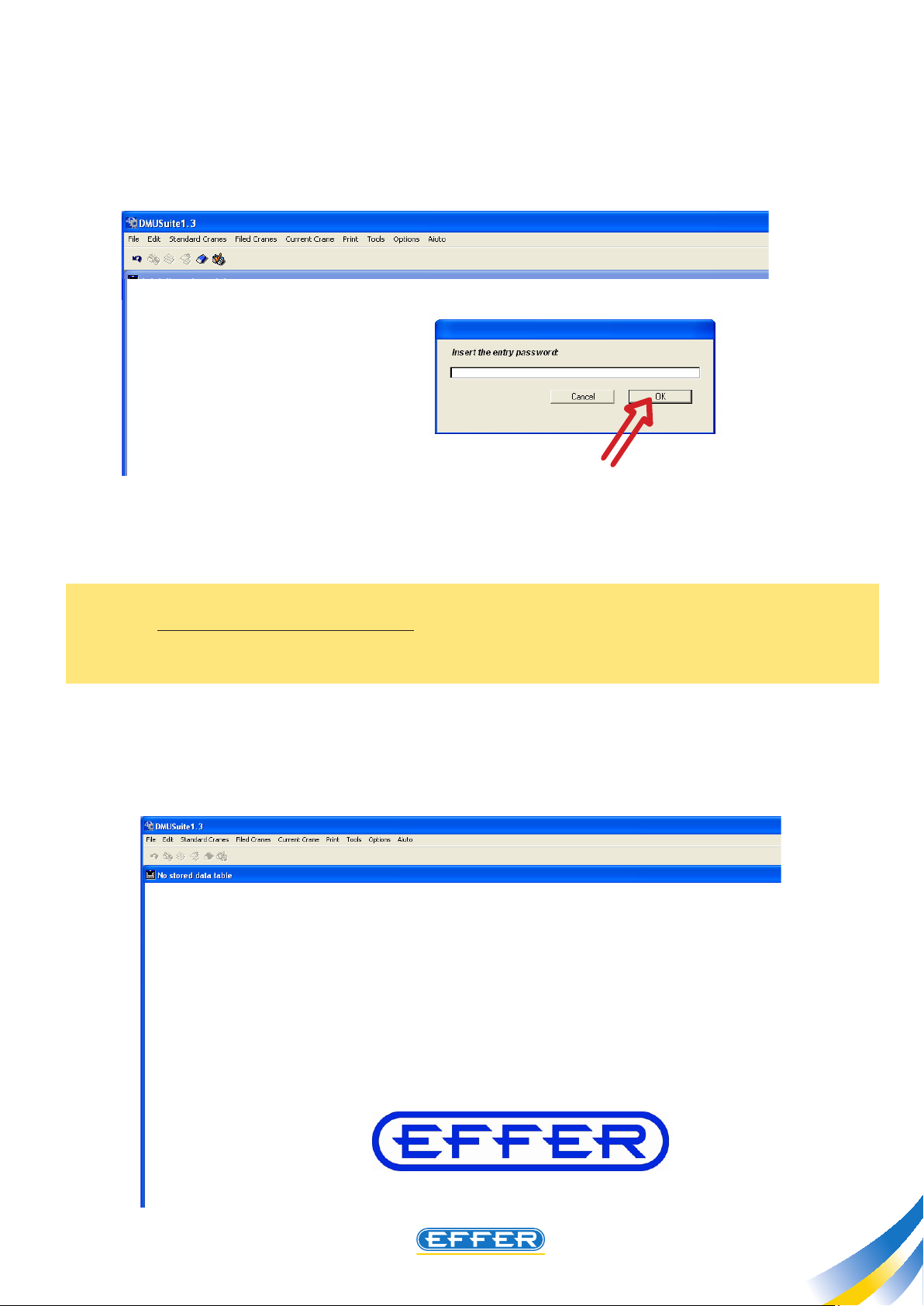
- A window “Enter the password to access” appears.
u Enter the password in CAPITAL LETTERS.
Note: This password is provided by Sol.Ge with the software, and the operator’s code linked to the
password will be stored in memory by DMU on which you will work. The password has a time limit: the
date of expiry shall be communicated with the password, and the operator has to request a new password at least 4 months before the deadline.
u CLICK OK
- The shown screen appears from which you can access the allowed functions explained in Chapter 7.
7
THE POWER OF PERFORMANCE
Electronic device DMU2000 - DMU3000 - DMU3000 PLUS
Electronic device DMU2000 - DMU3000 - DMU3000 PLUS
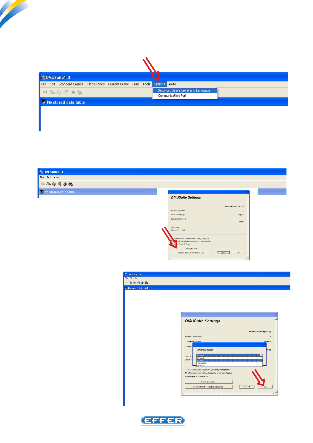
b) Changing the dialogue language
If you want to change the dialogue language, with the software already running:
u Click on the icon “Options”
u Click on the icon “User Level Settings and Language”
- The window “DMU settings” appears
u Click on the icon “Language Selection”
A list of the dierent languages present in the
software appears; select the language
u CLICK OK
u CLICK OK again
8

Electronic device DMU2000 - DMU3000 - DMU3000 PLUS
THE POWER OF PERFORMANCE
c) Quitting the software
u Click on the icon “File” with the cursor. You see a window, click on the icon “Quit” to exit the soft-
ware.
9
THE POWER OF PERFORMANCE
Electronic device DMU2000 - DMU3000 - DMU3000 PLUS
Electronic device DMU2000 - DMU3000 - DMU3000 PLUS
6. Instructions for communication port setting
If your laptop has a Serial Port compatible with the original cable provided, you need an USB adapter, and
you have to install the adapter drivers present in the setup CD.
u Insert the CD in the computer.
u Click the icon related to the USB
adapter software installation.
u CLICK “NEXT” :
NOTE: Sol.ge can supply an USB adapter,
see page 2.
NOTE:
In case there is no communication between the DMU and the computer, the words “ERROR 2” appear on the screen.
In this case, you have to match the communication port (COM 1 or COM 2) selectable in the software
from “Options”-” Communication port “, with the Port (COM 1 or COM 2) that is pre-set in the oper-
ating system.
10
Electronic device DMU2000 - DMU3000 - DMU3000 PLUS
THE POWER OF PERFORMANCE
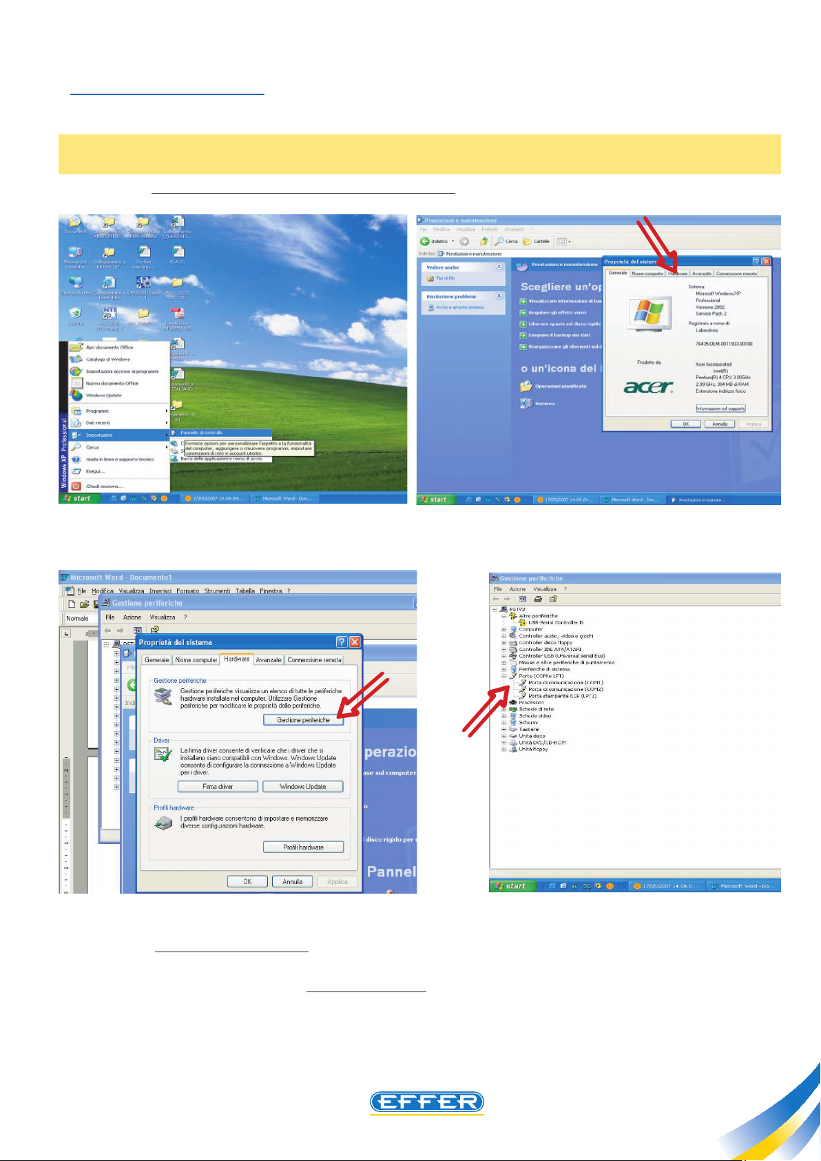
Operating instructions
Through the path “Start”, “Settings”, “Control Panel”, you must reach the system properties, led un-
der the icon “system”
N.B.: According to the type of display set on the computer, you may need to go through “Perfor-
mances and Maintenance”.
u In the “Hardware” menu click “Device Manager”.
u Select “COM ports and LPT” that you can nd in the drop-down menu. After you open the sub-
menu the code related to the USB cable connected to the PC appears. After selecting it, click Properties.
In the window that appears select “Set COM ports”.
Our software is designed to use both COM1 and COM2 ports:
u Select without distinction the free port on your personal computer.
11
THE POWER OF PERFORMANCE
Electronic device DMU2000 - DMU3000 - DMU3000 PLUS
Electronic device DMU2000 - DMU3000 - DMU3000 PLUS
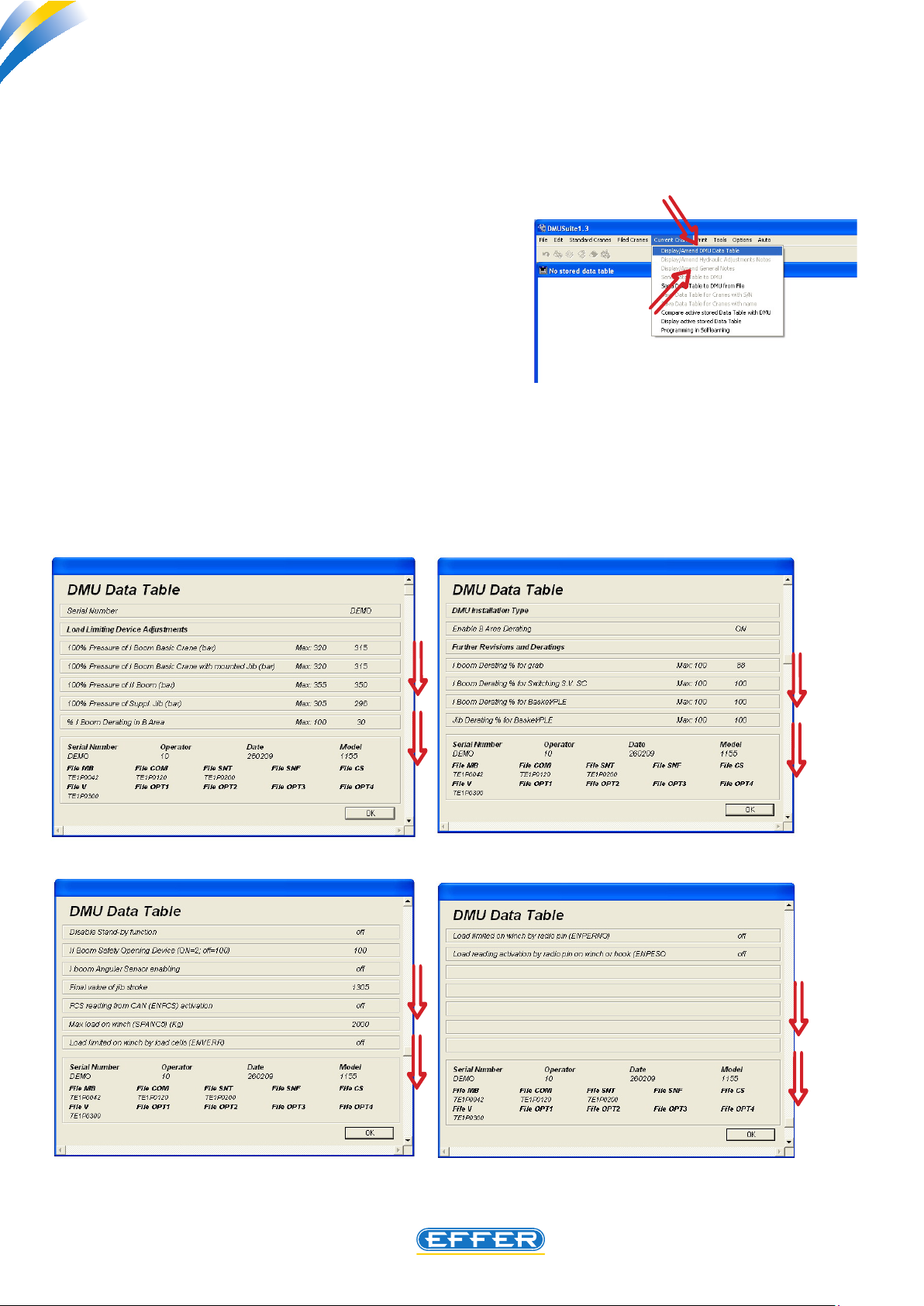
7. Explanation of changeable parameters
To access the management part concerning change in certain performance parameters, follow the
path:
u CURRENT CRANE
u DISPLAY/CHANGE DMU DATA SHEET
In the opening screen some setting values appear.
Using the vertical scroll bar, you can access the 17 available and changeable setting values.
12
Electronic device DMU2000 - DMU3000 - DMU3000 PLUS
THE POWER OF PERFORMANCE
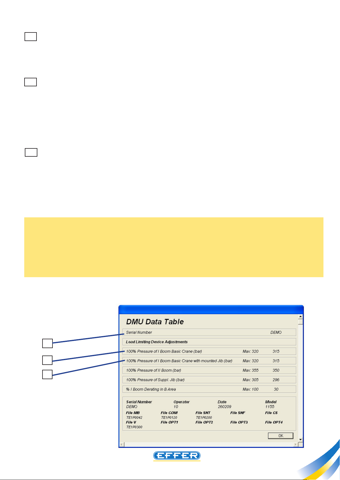
1 Serial number inside the DMU
The serial number inserted inside the DMU should be the same as the crane one. If the DMU tted to
the crane is to be replaced, a new one taken from stock shall be tted. This new device will therefore
not include the setting les, then you will have to enter not only these les which are provided by Sol.
Ge S.p.A. for the specic crane, but also the crane serial number in the box provided.
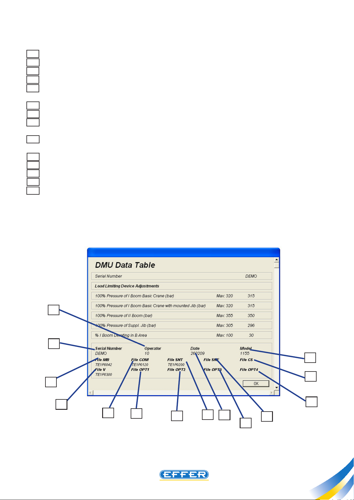
2 Pressure 100% basic crane 1st boom cylinder
The rst boom cylinder can have two dierent maximum pressures permitted for the use as basic crane
and for the use with additional jib: the setting value shown on the rst line concerns the operation of a
basic crane, i.e. a crane equipped with additional jib or that is working without the jib tted. When this
pressure value inside the rst boom cylinder is achieved, the load limiting device comes into operation.
If a performance downgrading of the basic crane is necessary, due to a problem of stability, (value to be
decreased according to practical tests) the load limiting device should be operated rst, by decreasing
the value on this line.
3 Pressure 100% basic crane 1st boom cylinder with Jib fitted
The setting value shown on the second line concerns the operation of the load limiting device when
the max. allowed pressure value inside the rst boom cylinder is achieved, operating with a crane, that
is working with the additional jib tted. If a performance downgrading of the basic crane is necessary,
following a problem of stability, (value to be decreased according to practical tests) the load limiting
device should be operated rst, by decreasing the value on this line.
Reductions of more than 50% of the original values are not recommended: should this necessity arise
please contact Sol.Ge S.p.A. technical oce.
NOTE: If a performance downgrading is required in the area of maximum performance for a problem
of stability, you can decrease the maximum pressure values inside the DMU, but it is not necessary to
reduce also the working pressure in the hydraulic circuit of the crane. When the operating lockout resulting from DMU setting comes into operation, the boom rise movements are still possible, but these
movements are automatically interrupted when performance is increased approximately by 10% compared to the set value.
1
2
3
13
THE POWER OF PERFORMANCE
Electronic device DMU2000 - DMU3000 - DMU3000 PLUS
Electronic device DMU2000 - DMU3000 - DMU3000 PLUS
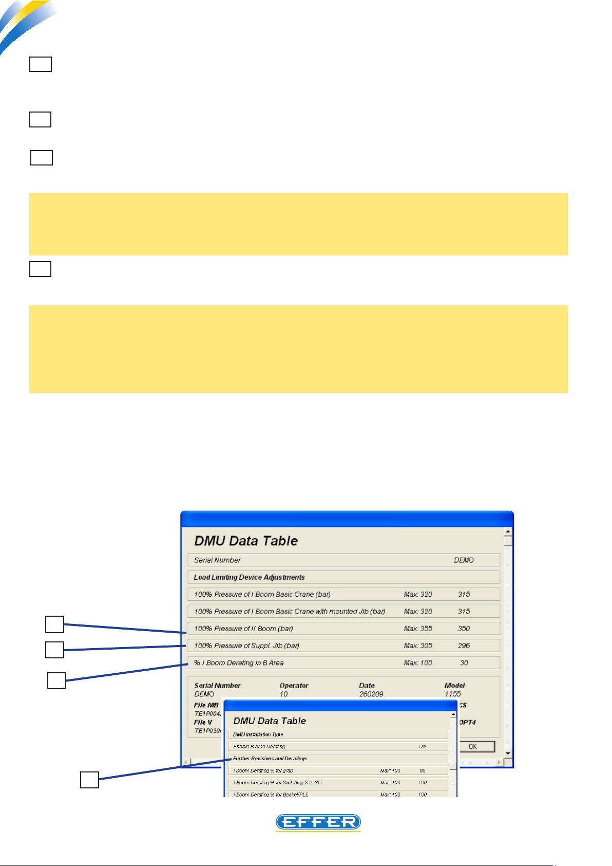
4 Pressure 100% 2nd boom cylinder
When this pressure value inside the second boom cylinder is achieved, the load limiting device is operated.
5 Pressure 100% additional jib cylinder
When this pressure value inside the jib cylinder is achieved, the load limiting device is operated.
6 % Downgrading 1st boom cylinder to work in B area
By changing this value, you change the crane performance relating to the front work area. Performance
is expressed as a percentage of the crane maximum lifting capacity .
NOTE: On crane models fitted with an encoder to determine the position of the crane booms with
respect to the truck longitudinal axis, zero is displayed instead of the value originally set, and to make
a change in performance in B Area, you should use the appropriate software interface called “SERVICE
MANUAL, edit stability parameters.
7 Cancel performance downgrading in B area
If the installation of the crane does not require any identication of the area “B”, related to performance
downgrading, if you select “OFF” you cancel this function.
NOTE: We recommend not setting the front working area by 100%, as the load limiting device operation would lead to functional restrictions relating to the manoeuvrability of the crane upper booms
owing to the off selection (e.g. when it comes into operation no rise manoeuvre with the crane booms
is allowed). If you must reverse the position of working area “A” with the position of the work area “B”,
you must operate mechanically cranes by moving the proximity switches or the cam: this change in
position is not possible using the DMU.
NOTE: Crane models fitted with an encoder to determine the position of the crane booms with respect
to the truck longitudinal axis, OFF appears and you cannot change it. In order to cancel performance
downgrading in B Area, you should use the appropriate software interface called “SERVICE MANUAL,
edit stability parameters“.
4
5
6
14
7
Electronic device DMU2000 - DMU3000 - DMU3000 PLUS
THE POWER OF PERFORMANCE
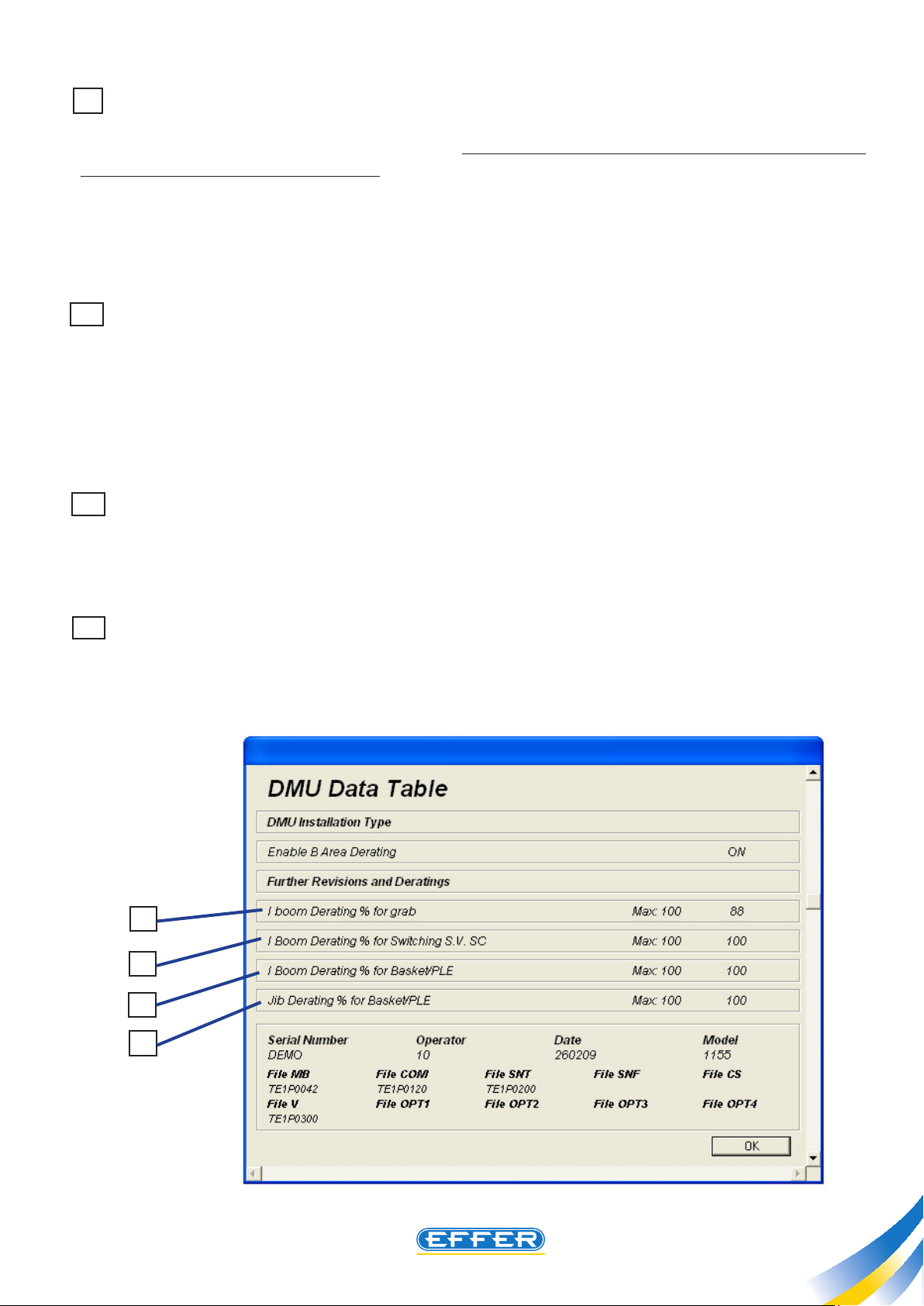
8 % Downgrading 1st boom cylinder for bucket
A control to operate a bucket is tted to the crane hydraulic control bank: we remind you that this control is hydraulically operated after the sequence of two manoeuvres to simulate closing, plus a manoeu-
vre to simulate opening are carried out. To return to the standard crane operation you must perform a
new start-up procedure of the device.
This implies a performance downgrading of the crane, already set at 12%.
By changing this value you have a consequent intervention of the load limiting device when the percentage of the performance set is achieved.
9 % Downgrading 1st boom cylinder for CS exchange solenoid valve
An exchange solenoid valve is tted to crane additional jib. This valve has the function to divert oil intended for a function of a crane jib to a bucket. This solenoid valve is operated by means of an electric
switch. Each time you turn this switch, a performance downgrading of the crane is operated, already
set at 12%.
By changing this value you have a consequent intervention of the load limiting device when the percentage of the performance set is achieved.
10 % Downgrading 1st boom cylinder for basket/PLE
If the use of the crane in the PLE function requires a limitation in horizontal outreach for stability problems you can change the load limiting device setting value. This downgrading does not aect the performance of the crane during normal work for lifting loads.
11 % Downgrading jib cylinder for basket/PLE
If the use of the crane in the PLE function requires a limitation in horizontal outreach only of the additional extensions for problems of additional jib load stability, you can change the setting value of the
load limiting device connected to jib: this downgrading does not aect the jib performance during
normal work for lifting loads.
8
9
10
11
15
THE POWER OF PERFORMANCE
Electronic device DMU2000 - DMU3000 - DMU3000 PLUS
Electronic device DMU2000 - DMU3000 - DMU3000 PLUS
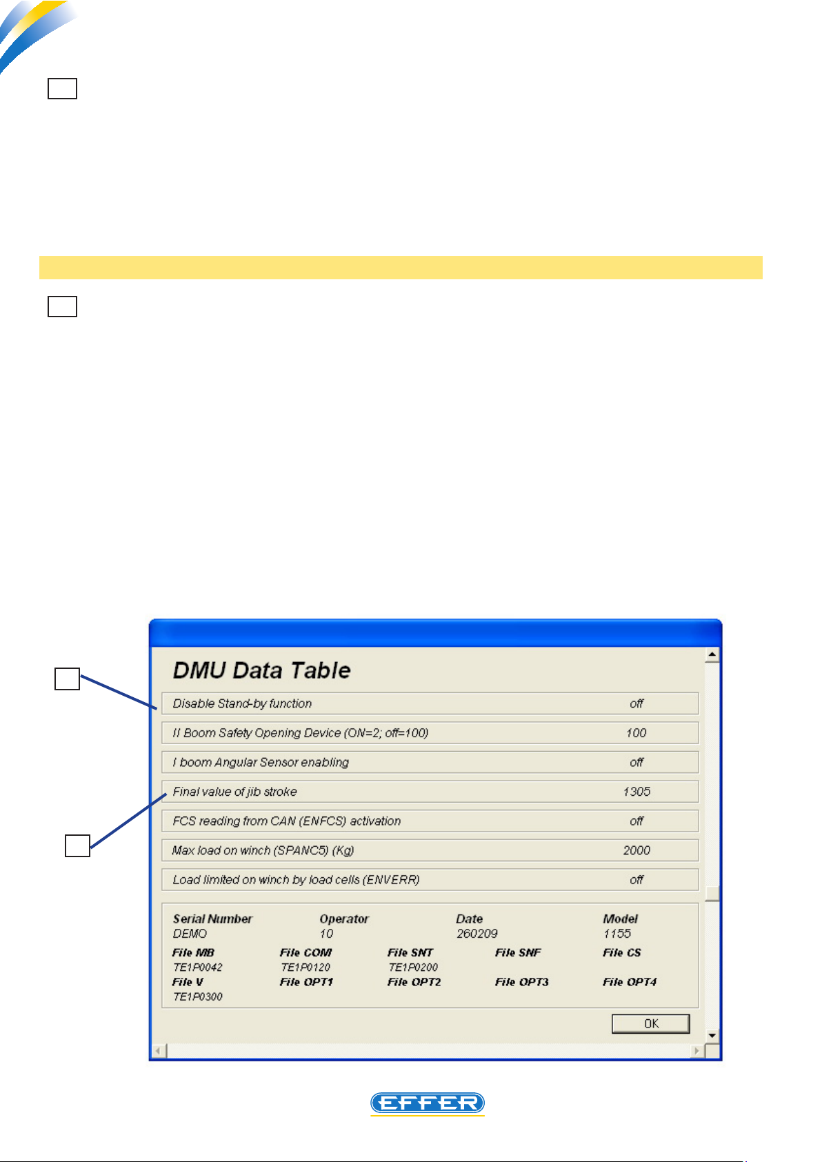
12 Jib stroke final value (Change in end-of-stroke point while additional jib is opening)
A proper setting of electronic angle sensor placed on additional jib makes crane lock not operational
when you run a manoeuvre of maximum opening, after the maximum pressure value inside the jib
cylinder is achieved.
In this case, use the RESET button to retrieve the crane movements. The movement of jib opening
should be discontinued by the angle sensor setting by preventing the jib cylinder from achieving its
maximum extension, even 0. 5 mm. only.
By editing this parameter the electronic end-of-stroke point related to jib opening is moved , thus
avoiding stopping crane operation without reason.
Note: Please see page 33 for further information.
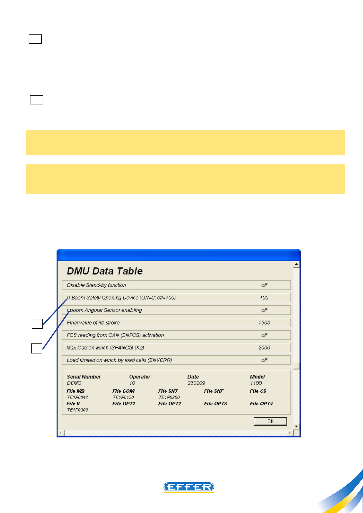
13 Disabling stand-by function
On all the DMUs the stand-by function is turned on: after 30 minutes during which the DMU is electrically operated but no movement with the crane is carried out, the electronic part with the highest
power input automatically switches o, thus limiting the electric consumption by truck batteries. (To
restore full crane operation it is necessary to press the stop emergency button, and after it is released
operate the RESET button). Certain operators may nd this procedure complicated, therefore the necessity to cancel the stand-by function may arise.
If ON is set in the computer screen, the stand-by function is disabled.
If OFF is set in the computer screen, the stand-by function is enabled.
13
12
16
Electronic device DMU2000 - DMU3000 - DMU3000 PLUS
THE POWER OF PERFORMANCE
14 2nd boom safe opening device (ON=2; OFF=100)
You can operate an automatic device which stops the crane opening manoeuvre when the crane is
folded behind cab - if the second boom cylinder, on the rod side, has not sucient pressure inside to
prevent the second boom from falling down as soon as it releases from the support tted to the column.
The crane shall be delivered with the device o (the number 100 appears on the box).
15 Enabling angular sensor to detect 1st boom position
As the anti-bridge function is installed, an angle sensor is tted to the rst boom, and the function must
be enabled otherwise the DMU reports an error.
Enable is on when the box is selected (tick).
NOTE: the DMU emits an output electric signal, according to the position of the crane boom. This
signal controls the operation of an alarm, or better, prevents crane stabilizers from rising , when crane
boom is in wrong position.
The authorization above is only possible on cranes where the DMU 2000 or DMU 3000 are fitted . On
cranes where the DMU 3000 PLUS is fitted, OFF appears next to this indication and you cannot use
this function.
14
15
17

THE POWER OF PERFORMANCE
Electronic device DMU2000 - DMU3000 - DMU3000 PLUS
Electronic device DMU2000 - DMU3000 - DMU3000 PLUS
16 Winch maximum capacity ( maximum weight )
A value expressed in kg appears next to this indication: this is an indication of the weight on the
hook which should not be exceeded when using the winch. Otherwise all crane boom lifting movements and winch lifting movements are automatically stopped.
In order to use this function the optional “radio pin” or “winch proportional load cell” must be fitted to
the crane. Please note that the value of weight which appears next to this indication is relating to the
use of the winch in one-cable lifting configuration (direct pull).
17 Detecting winch load with load cell ( enverr )
Depending on the type of crane, and the type of winch fitted, it may happen that instead of the
traditional “torque limit”, a proportional load cell is fitted to the same winch to limit the maximum capacity of the load applied to the hook. In these specific cases, you get crane good operation if ON appears next to such indication.
If off appears the crane is inoperative.
18 Detecting pin load on winch (enperno)
Depending on the type of crane, and the type of winch fitted, it may happen that instead of the traditional “torque limit” a proportional load cell is fitted to the hook connecting pin to limit the maximum
capacity of the load applied to the hook . In these specific cases, you have the good operation of the
crane if ON appears next to the indication.
If off appears the crane is inoperative.
19 Enabling load reading with radio pin on winch or hook ( enpeso )
The cranes which are not provided with the function described in paragraph 17 or 18 a pin for the
junction of the hook to the crane can be installed - always as an option - with a proportional load cell
at its interior, with which it is possible to have an indication of the value of the load applied to the hook.
This value can be read on the display of the radio pushbutton panel. To use this function, ON should
appear next to the indication.
Off disables the function.
18
Electronic device DMU2000 - DMU3000 - DMU3000 PLUS
THE POWER OF PERFORMANCE
Other available data:
A Crane serial number (it must correspond to the serial numer marked on the crane)
B This code identies the last operator who made a change in a parameter in the DMU device
C The date that appears is the last change made in a parameter in the DMU device
D Sets out the crane model
E This code identies the type of programming entered for the conguration of the particular
version of cranes
F This optional code identies a customised remote control
G This code identies the type of programming entered for the conguration of the jib
H This code identies the type of programming entered for the conguration of the jib, if the jib
is made of two part, or is customised.
I This code identies the type of programming entered for the conguration of the
supplementary controls (ex. bucket and rotor)
L This code identies the type of programming entered for the conguration of the winch
M This code identies the type of programming entered for special congurations
N This code identies the type of programming entered for special congurations
O This code identies the type of programming entered for special congurations
P This code identies the type of programming entered for special congurations
B
A
D
I
E
L
F
M
N
G
C
H
P
O
19
THE POWER OF PERFORMANCE
Electronic device DMU2000 - DMU3000 - DMU3000 PLUS
Electronic device DMU2000 - DMU3000 - DMU3000 PLUS
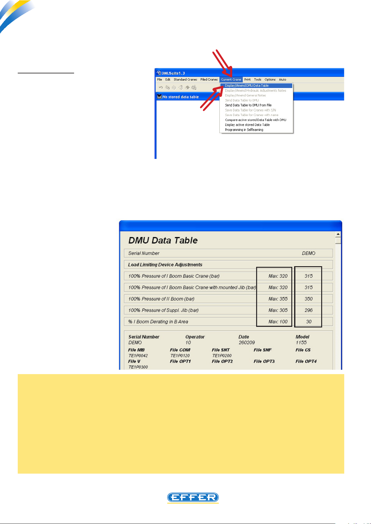
8. Displaying/changing available data in the software
a) DISPLAYING
To display and change the data in the
DMU tted to the crane it is necessary
to:
u Click on the icon “Current Crane”
u Click on the icon “Display/Change
DMU Data Sheet”
- The software runs the data uploading inside the DMU on the computer.
You must wait a few seconds to run the operation.
- “DMU Data Sheet” window appears
In column A on the
left, the maximum
setting values allowed for this project are shown, while
in the column B the
set setting values
are shown.
Why are the maximum pressure values higher than setting values???
The setting values ensure that the crane is able to handle the loads indicated in the load diagrams with
an “ideal” hydraulic system, i.e. with values of back-pressure on oil exhaust pipes almost close to zero:
If this is not found on a specic installation, you can raise the values in last column up to the maximum
values allowed. Thus the DMU device delays its operation, and the crane increases its performance.
As to the setting value for the work in front of the cab, (rst boom downgrading in B area) the setting
value that appears is the value resulting from the application of the crane to the truck, which is the
minimum possible in respect of the weights on the axes only: in case the specic truck allows operating
in conditions of stability with higher performance, you can change this value, i.e. increase it.
A
B
20
Electronic device DMU2000 - DMU3000 - DMU3000 PLUS
THE POWER OF PERFORMANCE
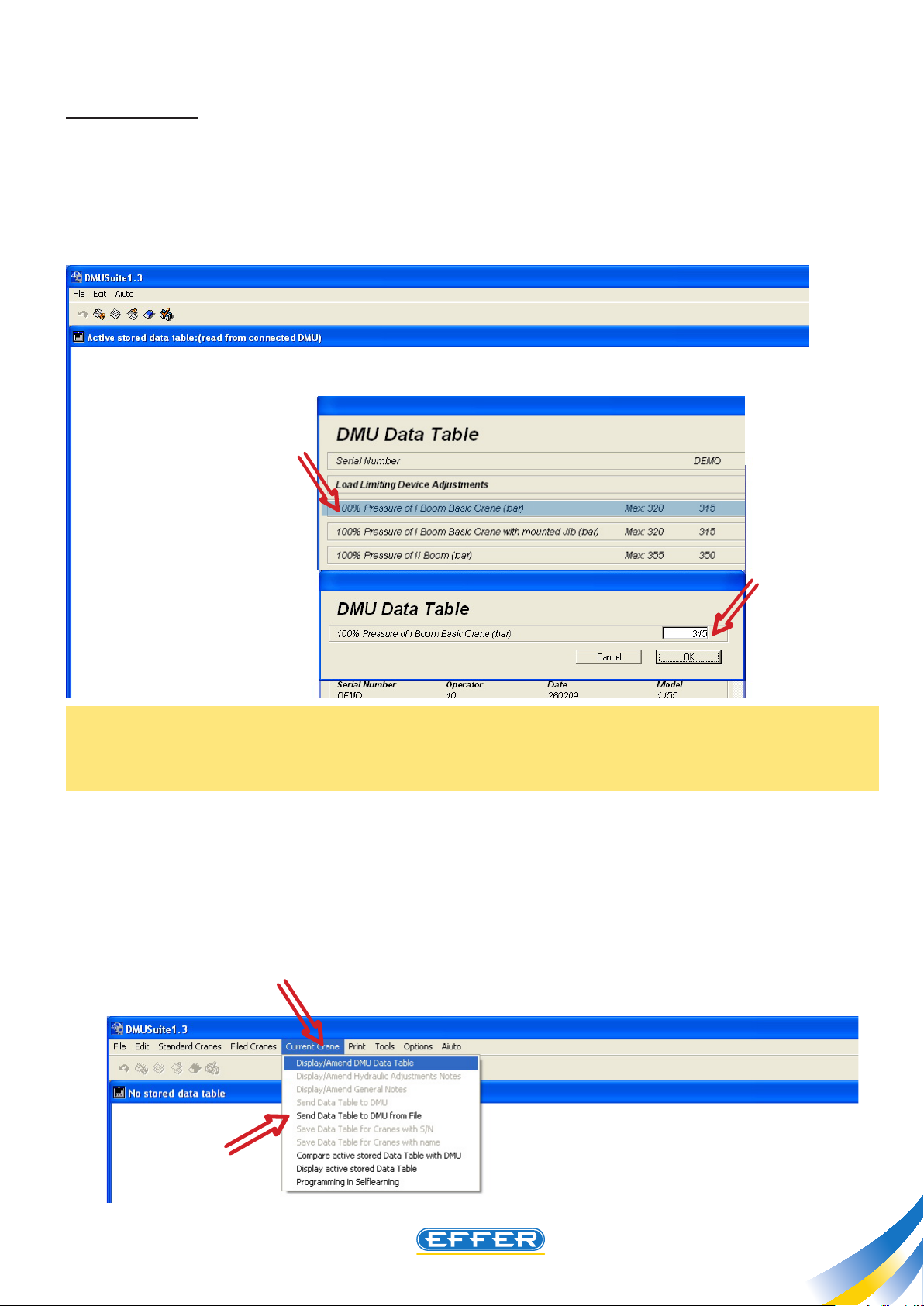
b) CHANGING
The data that can be changed are those in the right column, called B in the previous paragraph.
u Click twice on the line that you want to change: only the selected line is still highlighted.
u Type the desired value in the box..
N.B.: The value does not exceed the maximum value allowed as stated on the previous screen, otherwise the system does not accept it, i.e. even if a higher value is typed, the maximum allowed value is
recorded inside the DMU.
u CLICK OK
u Exit the screen by CLICKING OK
The changed data shall be conveyed to DMU.
u Click on the icon “Current Crane”
u Click on the icon “Send Data Sheet to DMU”
21
THE POWER OF PERFORMANCE
Electronic device DMU2000 - DMU3000 - DMU3000 PLUS
Electronic device DMU2000 - DMU3000 - DMU3000 PLUS
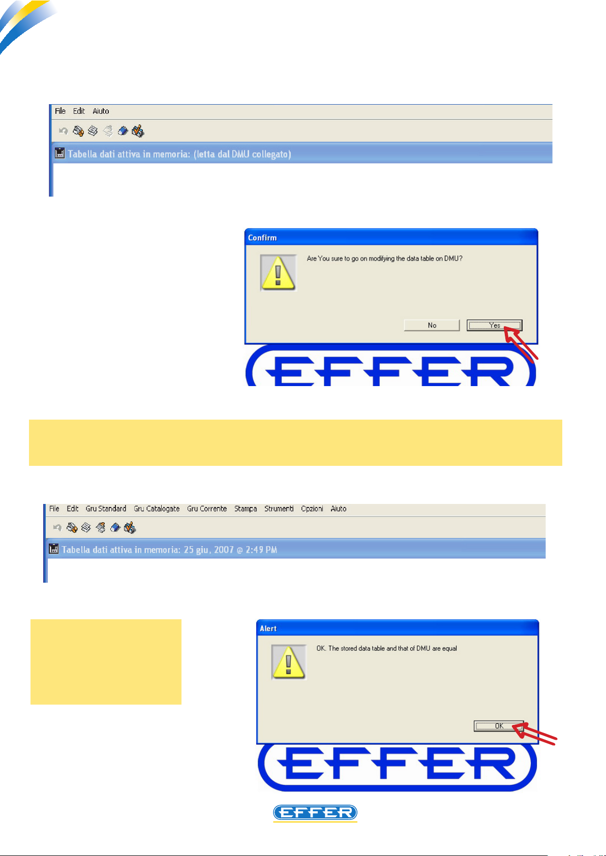
A dialog box appears and asks if you really want to change the data inside the DMU.
u CLICK YES
- Wait for a few seconds.
- To conrm the variation, the DMU emits a
sound.
Further conrmation of your change in the data is given by the dialog box that appears after the
comparison of data sent and those stored.
u CLICK OK
While carrying out a
change in the values of
the data inserted inside
the DMU, the DMU must
not be in stand-by.
22
 Loading...