

Page 1
D0019203
Betriebs- und
Installationsanleitung
GB Operating and Installation Instructions p 45
Sicherheit und Präzision
Fluchttürsteuergerät 720-30
720-32
Page 2

2
1 Betrieb und Funktion ........................................................3
1.1 Türterminal........................................................................ 4
1.2 Übersichtstabelle Betriebsanzeigen..................................................... 5
1.3 Überwachungs- und Alarmfunktionen ................................................... 6
1.3.1 Betätigung der Nottaste ....................................................... 6
1.3.2 Tür offen Überwachung ....................................................... 6
1.3.3 Verriegelungsüberwachung .................................................... 6
1.3.4 Sabotage der Tür ............................................................ 6
1.3.5 Sabotage am Türterminal, Terminal-Modul oder Bedienteil ........................... 6
1.3.6 Sabotage der Leitungen ...................................................... 6
1.4 Schaltfunktionen ................................................................... 7
1.4.1 Kurzzeitfreigabe ............................................................. 7
1.4.2 Dauerentriegelung ........................................................... 7
1.4.3 Verriegelung ............................................................... 7
1.4.4 Alarmrückstellung ........................................................... 7
Besonderheiten beim Terminal-Modul 1370-10 ................................................... 8
Zerstörungsfreie / zerstörende Betätigung des Notschalters. ................................. 8
Öffnen der Abdeckhaube ............................................................. 8
1.5 Funktionsvarianten.................................................................. 9
1.5.1 Kurzzeitfreigabe ............................................................. 9
1.5.2 Dauerentriegelung ........................................................... 9
1.5.3 Voralarm .................................................................. 9
1.5.4 Alarm ..................................................................... 9
1.5.5 Alarmzeit .................................................................. 9
1.6 Sonderfunktion I: Anlagen mit indirekter Freischaltung. Das Fluchttürsteuergerät 720-32 .......... 10
1.7 Sonderfunktion II: Betrieb des Fluchttürsteuergeräts mit dem Elektro-Sicherheitsschloß 809 ....... 11
1.8 Sonderfunktion III: Betrieb am effeff-Türsteuerbus mit Steuerungstableau 925 .................. 12
1.9 Ermittlung einer Alarmbedingung ...................................................... 13
1.10 Beseitigung der Alarmursachen ....................................................... 14
2 Installation ...............................................................15
2.1 Montage des Steuergeräts ........................................................... 16
2.2 Allgemeine Hinweise zur elektrischen Installation ......................................... 17
2.3 Kabelpläne und Anschlußdetails ...................................................... 18
2.3.1 Fluchttürsicherung für eine einflügelige Fluchttür (Kabelplan) ........................ 18
2.3.2 Fluchttürsicherung für eine zweiflügelige Fluchttür (Kabelplan) ....................... 19
2.3.3 Netz- und Akkuanschluß ..................................................... 20
2.4 Verriegelungssysteme mit dem Türterminal 1337-10/11 .................................... 22
2.4.1 Anschlußdetail paralleler Anschluß Bedienteil 1332 und Türterminal 1337-10/11 ......... 22
2.4.2 Anschlußdetail: Paralleler Anschluß von zwei Türterminals 1337-10/11 ................. 23
2.4.3 Gesamtanschlußplan 720-30 mit Türterminal 1337-10/11 ........................... 24
2.5 Verriegelungssysteme mit dem Terminal-Modul 1370-10 ................................... 26
2.5.1 Anschlußdetail: Terminal-Modul 1370-10 mit Bedienteil 1332 ........................ 26
2.5.2 Anschlußdetail paralleler Anschluß zweier Terminal-Module 1370-10 .................. 27
2.5.3 Gesamtanschlußplan 720-30 mit Terminal-Modul 1370-10 ........................... 28
2.6 Anlagen mit indirekter (zentraler) Freischaltung (Sonderfunktion I) ............................ 30
2.6.1 Anschlußschema indirekte (zentrale) Freischaltung ................................ 31
2.6.2 Gesamtanschlußplan 720-32 ................................................. 32
2.7 Einstellschalter für Funktionen und Zeitabläufe ........................................... 34
2.7.1 Werkseitige Stellung der Einstellschalter ........................................ 34
2.7.2 Zeitvorgaben .............................................................. 35
2.7.3 S 5 Funktionsvarianten ...................................................... 35
2.7.4 S 6 Busadresse............................................................ 36
2.7.5 S 7 Sonderfunktionen ....................................................... 36
2.8 Steuereingänge ................................................................... 37
2.9 Meldeausgänge ................................................................... 37
2.10 Anschluß von Brandmeldern (Klemmen 45-46) ........................................... 38
2.11 Sonderfunktion II: Betrieb des Fluchttürsteuergeräts mit dem Elektrosicherheitsschloß 809 ........ 39
2.12 Sonderfunktion III Betrieb der Steuerung am Steuerungstableau 925 (Bus-Technologie) .......... 40
2.13 Technische Daten ................................................................. 41
3 Inbetriebnahme, Wartung, wiederkehrende Prüfung ............................. 42
3.1 Inbetriebnahme und wiederkehrende Prüfung ............................................ 42
3.2 Wartung ......................................................................... 42
4 Checkliste zur Prüfung vor Erstinbetriebnahme ................................43
GB Operating and Installation Instructions ................................45ff
Page 3

3
Achtung!
Für die Installation und den Betrieb von elektrischen Verriegelungen von Türen in
Rettungswegen sind baurechtliche Bestimmungen zu beachten!
Die Übereinstimmung der Gerä te mit der “Richtlinie über elektrische Verriegelungssysteme von
Türen in Rettungswegen (EltVTR 12/97)” (Bauregelliste A Teil 1, lfd. Nr. 6.19) ist geprüft vom TÜV
Rheinland, Köln.
Nr. des Prüfzertifikats: R 2011393
1 Betrieb und Funktion
Türen im Verlauf von Rettungswegen – Fluchttüren – müssen sich von innen jederzeit leicht und
ohne fremde Hilfsmittel öffnen lassen. Ihre Schlösser müssen deshalb eine Panikfunktion enthalten,
also bei Betätigung des Innendrückers auch den vorgeschlossenen Riegel zurückschließen. Andererseits sollen die Türen aus Sicherheitsgründen verschlossen sein. Dies führt in sehr vielen Fällen in
Verwaltungsgebäuden, Kaufhäusern, Industrieanlagen und ähnlichen Objekten zu Problemen. Die
betreffenden Türen können nicht mehr wirkungsvoll kontrolliert werden.
Um diese Situation mit vertretbarem Aufwand unter Kontrolle zu bekommen, werden Systeme
eingebaut, welche die Türen elektrisch verriegeln, ihren Verriegelungszustand überwachen und ihre
Öffnung oder Entriegelung melden.
Für die Öffnung im Notfall sind solche Systeme – von Ausnahmefällen abgesehen – immer mit
einem Notschalter ausgestattet, dessen Betätigung die elektrische Verriegelung unverzüglich abschaltet und die Tür damit für die Begehung freigibt und einen Alarm auslöst.
Die Verriegelungselemente müssen die Tür mit einer ausreichenden Haltekraft zuhalten und im
Notfall, auch wenn sie unter Vorlast stehen, sicher entri egeln.
Darüber hinaus müssen solche Systeme auch gewisse Steuerfunktionen bieten, damit sie im
Bedarfsfall kurzzeitig oder auch dauernd freigeschaltet werden können.
Außerdem muß die Notentriegelung der Tür durch eine gegebenenfalls vorhandene Brandmeldeanlage möglich sein.
Als Zusatzfunktion besitzt das effeff-Fluchttürsteuergerät 720-30/32 eine Auswerteeinheit für effeffRauchmelder.
Als Bedien- und Meldegerät z um effeff- Flucht t ürst euer gerät dient im Normalfall das Fluchttürterminal
1337-10/11 oder das Terminal-Modul 1370-10. Parallel dazu kann ein Bedienteil 1332 – zum Beispiel
als Außenbedienteil – und auch ein zentrales Steuerungstableau auf das Fluchttürsteuergerät aufgeschaltet werden.
In Ausnahmefällen, nämlich dann, wenn die Freischaltung der Tür(en) nur von zentraler Stelle aus
erfolgen soll, kann das Bedienteil 1332 auch als alleiniges Schalt- und Anzeigeelement direkt an der
Tür eingesetzt werden. Es sind dann jedoch besondere Vorschriften zu beachten, und als Steuergerät
ist dann Modell 720-32 einzusetzen, das mit einer speziellen Si cherheits-Relaisschaltung ausgestat tet
ist.
Page 4
Ñ
Ò
Ó
Ô
Õ
Ö
1337-10
1370-10
Ñ
Ò
Ó
Ô
Õ
Ö
4
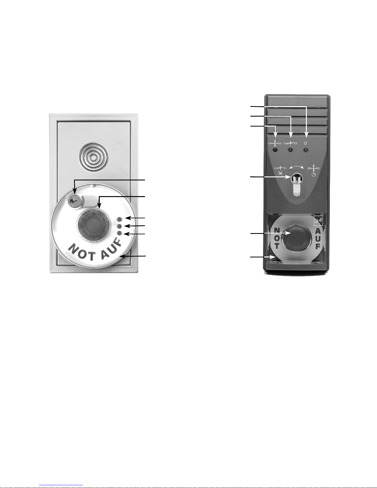
Abbildung 2: Terminal- Modul 1370-10 und Türterminal 1337 D0019203G0000100
1.1 Türterminal und Terminal-Modul
Als Schalt- und Anzeigegerät der Fluchttürsicherung dient gewöhnlich ein Türterminal 1337-10/11 oder
dasTerminal-Modul 1370-10 (Abbildung 2) (Ausnahmen siehe Seite 9: “Sonderfunktion I ...”) Es enthält drei
Leuchtdioden zur optischen Anzeige des Betriebszustandes, einen Schlüsselsc halter für alle betriebsmäßigen
Schaltfunktionen, die rote, beleuchtete Pilztaste für die Freischaltung und, im Gehäuse integr iert, einen Alarmsummer.
Das wichtigste Element von T ürterminal und Term i- Über den im Türterm inal oder Terminal-Modul
nalmodul nach Abbildung 2 ist der Notschalter , des- integrierten Schlüsselschalter
Ô können alle betriebs-
sen Bet ätiger als r ote, beleuc htete Pilztas te ausge- mäßigen Funktionen des Fluchttürsich erungssystems
führte ist
Õ. Er unterbricht bei Betätigung den Strom- wie Kurzzeit- und Dauerentriegelung, Verriegelung
kreis des Verriegelungselements und entriegelt es und Alarmquittierung geschaltet werden.
damit. Gleichzeitig wird ein Alarm ausgelöst. Der Betätigungspilz rastet ein und muß vor der Rückstellung Drei Leuchtdioden zeigen den momentanen Zustand
des Alarms wieder herausgezogen werden. des Verriegelungssystems an:
Beim Türterminal 1337-10/11 wird die Abdeckhau- Die gelbe Leuchtdiode
Ñ zeigt einen anstehenden
be des Notschalters
Ö bei Betätigung mit einge- Alarm an.
drückt, dabei jedoch nicht beschädigt. Sie kann ohne Die grüne Leuchtdiode
Ò zeigt eine entriegelte Tür
Hilfsm ittel abgezogen und nach dem Herausziehen an.
des Schaltpilzes wieder eingesetzt werden. Die rote Leuchtdiode
Ó zeigt eine verriegelte Tür an.
Beim Terminal-Modul 1370-10 wird bei einer Notschalterbetätigung nur die rote Abdeckkappe des
Schaltpilzez eingedrückt. Zur Rücks tellung des Notschalters muß die Klarsicht-Abdeckhaube
Ö mit Hilfe
des Schlüssels zunächst entriegelt werden.(Näheres
siehe Seite 8.)
Page 5
5
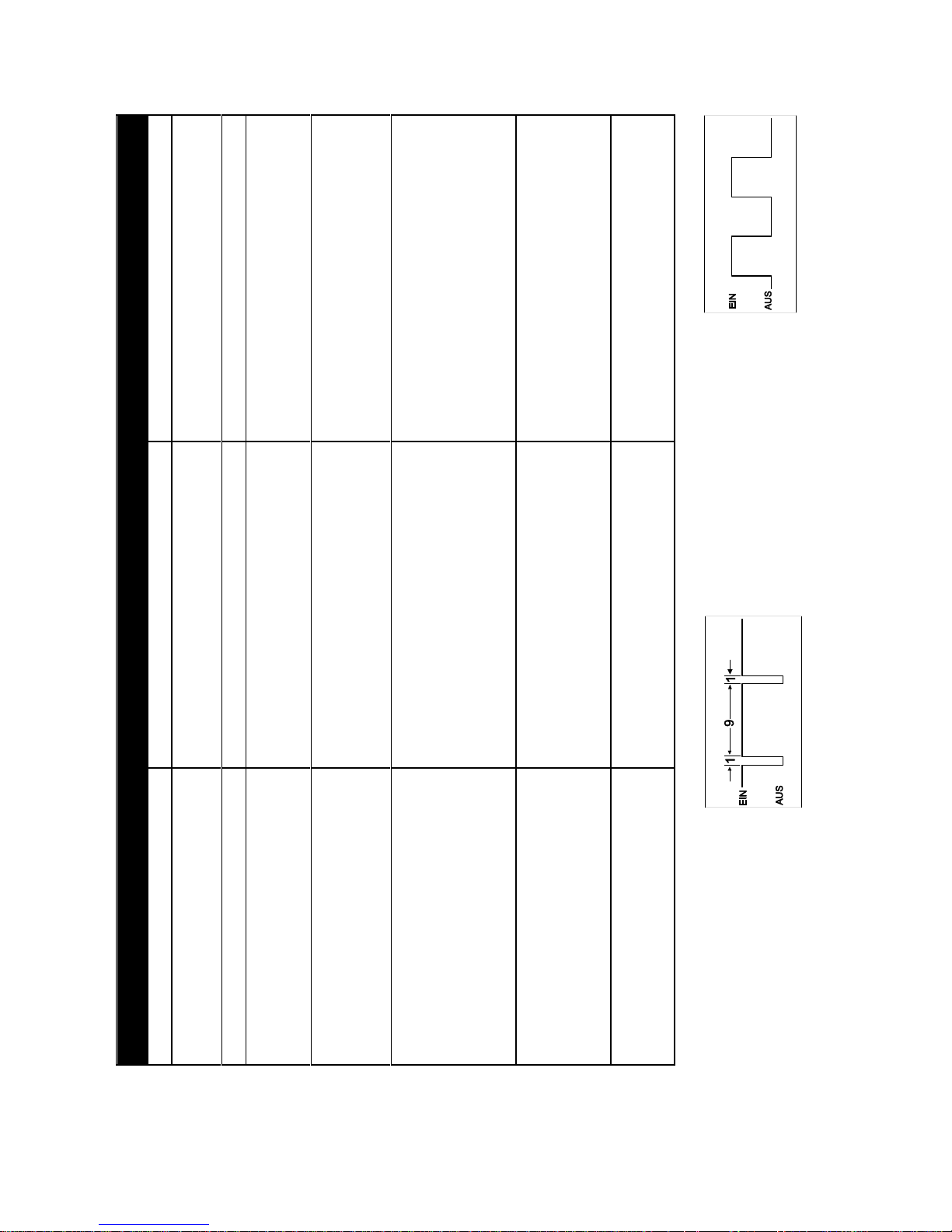
Es leuchten LED(s) Betriebszustand Bemerkungen
ROT
Verriegelung aktiv
GRÜN
Dauerfreigabe
Die Tür kann durch Schlüsseldrehung nach rechts
verriegelt werden. Ist dies nicht möglich, so ist sie
nicht geschlossen.
GELB
Alarm
GRÜN BLINKEND
mit kurzen Pausenzeiten (*)
Ablauf einer Kurzzeitfreigabe
Der Zeitablauf wird durch Öffnen und Schließen der
Tür automatisch abgebrochen.
Er kann durch Schlüsseldrehung nach rechts manu-
ell abgebrochen werden.
GRÜN BLINKEND
mit gleichlangen Pausen-
und Leuchtzeiten (**)
Es ist ein Alarm ausgelöst worden. Dieser wurde
zwar quittiert, die Alarmursache steht jedoch noch
an.
Die Alarmursache kann mit Hilfe der Tabelle auf Sei-
te 8 ermittelt werden. Nach Beseitigung der Alarm-
ursache (die grüne LED leuchtet dann dauernd)
kann die Tür durch eine Schlüsseldrehung nach
rechts wieder verriegelt werden.
GRÜN und GELB
Gefahrenalarm
Mögliche Alarmursachen:
C
Der Notschalter ist betätigt worden.CEin Rauchmelder hat ausgelöst.
C
Die Brandmeldezentrale hat ausgelöst.
C
Ein Verriegelungsbefehl konnte nicht aus-
geführt werden.
Diese Anzeige erscheint auch, wenn bei entriegelter
Tür das Terminalgehäuse geöffnet wird.
ROT und GELB
Sabotagealarm
Die Verriegelung der Tür bleibt aktiv.
Mögliche Alarmursachen:
C
Das Gehäuse des Türterminals bzw
Terminal-Modul wurde geöffnet.
C
Der Türkontakt wurde geöffnet (Sabotage
an der Tür).
GELB BLINKEND
Rot und Grün gemäß Schaltzustand.
Akkubetrieb
(Netzausfall)
Bei Netzwiederkehr stellt sich diese Anzeige auto-
matisch zurück.
Das Gerät behält seinen Schaltzustand bei.
Überbrückungszeit mindestens 15 Min.
(*) Das Impu ls-Pausen-Verhältnis beträgt ca. 9:1.
Dies bedeutet, daß die Leuchtphase neunmal
länger ist als die Dunkelphase.
(**) Das Impuls-Pausen-Verhältnis beträgt
ca. 1:1. Dies bedeutet, daß Leuchtphase und
Dunkelphase etwa gleich lang sind.
D0019203T0000100
1.2 Übersichtstabelle Betriebsanzeigen
Page 6

6
1.3 Überwachungs- und Alarm-
funktionen
Jeder Alarm des Fluchttürsicherungssystems
muß über den Schlüsselschalter im Türterm inal
oder erminal-Modul zurückgestellt werden,
nachdem zuvor das auslösende Alarmkriterium
behoben wurde.
Wird nach einer Alarmau s lösung der Schlüsselschalter ohne vorherige Beseitigung der Ursache des Alarms betätigt, so wird dieser lediglich quittiert. Die externe Signalisierung und
das akustische Signal im Türterminal oder
Terminal-Modul werden abgeschaltet, di e gelbe
LED erlischt, die grüne LED schaltet um auf
Blinksignal. Die Wiederverriegelung der Tür ist
nicht möglich.
1.3.1 Betätigung der Nottaste
Das Eindrücken der Nottaste bewirkt eine
unverzügliche Freischaltung der Tür und löst
grundsätzlich einen Alarm aus. Das akustische
Alarmsignal wird durch eine Betätigung des
Schlüsselschalters nach links abgeschaltet
(Quittieren des Alarms) .
Um die Tür wieder zu verriegeln, muß zunächst die eingedrückte Nottaste wieder herausgezogen werden. Eine Schlüsseldrehung
nach rechts verriegelt dann di e Tür wieder.
1.3.2 Tür offen Überwachung
Mit dem Öffnen einer Tür, die auf Kurzzeitfreigabe geschaltet wurde, wird für die von der
eingestellten Kurzzeitfreigabezeit noch verbleibende Zeit eine Überwachungsfunktion aktiviert. Wird die Tür innerhalb dieser "Türüberwachungszeit” nicht geschlossen, so wird zunächst durch einen intermittierenden akustischen Voralarm mit verminderter Lautstärke
gewarnt und nach Ablauf der Voralarmzeit ein
Alarm ausgelöst.
Wi rd die Tür innerhalb der Voralarmzeit geschlossen, so verriegelt sie. Es wird kein Alarm
ausgelöst.
Wird die Tür erst nach Auslösung des
Alarms geschlossen, werden die externe Alarmmeldung und die akustische Alarmmeldung im
Türterminal oder Terminal-Modul abgeschaltet.
Die Tür wird verriegelt, und die optische Anzeige zeigt weiterhin einen anstehenden Alarm an.
Es ist dann eine Quittierung des Alarms und
manuelle Rückstellung am Schlüsselschalter
des Türterminals oder Terminal-Moduls erforderlich.
Identische Abläufe ergeben sich, wenn die
Tür beim Abschalten einer Dauerentriegelung
offen steht.
1.3.3 Verriegelungsüberwachung
Wenn die verwendeten Verriegelungselemente entsprechende Überwachungskontakte
besitzen, wird auch die Aufrechterhaltung des
Zustandes “verriegelt” und die er folgreiche Ausführung des Befehls “verriegeln” bei geschlossener Tür überwacht.
Beim Flucht türöffner 331 RR AKRR wird diese Funktion durch den Ankerkontakt überwacht;
beim Flächenhaftmagneten 828 meldet ein integriertes Hall-Element den vollständigen Aufbau
des verriegelnden Magnetfeldes.
Wi rd also beim Einsatz des Modells 828 die
Tür gewaltsam aufgebrochen, oder kann bei
geschlossener Tür ein Verriegelungsbefehl
nicht realisiert werden, weil beispielsweise die
Haftgegenplatte nicht am Magneten anliegt,
wird Alarm ausgelöst.
1.3.4 Sabotage der Tür
Wi rd eine verriegelte Fluchttür in einer Weise sabotiert, die durch den Türkontakt bzw. den
im Fluchttüröffner integrierten Rückmeldekontakt erkannt werden kann, so wird unverzögert
ein Alarm ausgelöst. Eine Entriegelung der Tür
erfolgt bei diesem Sabotagealarm nicht.
1.3.5 Sabotage am Türterminal, Terminal-
Modul oder Bedienteil
Das Bedien- und Anzeigegeräte sind durch
einen Deckelkontakt geschützt. Bei einem Sabotageversuch durch Öffnen des Geräts wird
ebenfalls unverzüglich Alarm ausgelöst. Auch
bei diesem Sabotagealarm wird die Tür nicht
entriegelt.
1.3.6 Sabotage der Leitungen
Die Leitungen zwischen Fluchttür steuergerät
und Verriegelungselement werden ebenfalls
überwacht. Eine Leitungsunt erbr echung führt zu
einer unverzügli chen Al armauslösung.
Page 7

7
1.4 Schaltfunktionen
Der S chlüsselschal ter des Türterminals oder
Terminal- Moduls hat zwei Tastfunktionen, die –
je nach Ausgangszustand – unterschiedliche
Schaltvorgänge auslösen.
1.4.1 Kurzzeitfreigabe
Aus dem Zustand “verriegelt” nach
rechts tastend wird eine Kurzzeitfreigabe geschaltet. Dies bedeutet, daß
die Bestromung des Verriegelungs-
teils für eine bestimmte Zeit unterbrochen und
nach A blauf dieser Zeit automatisch wieder eingeschaltet wird. Die Tür kann innerhalb dieser
Zeit einmalig begangen werden. Mit dem
Schließen der Tür wird die Freigabezeit abgebrochen. (Beachte nebenstehend “Tür offen
Überwachung”!)
1.4.2 Dauerentriegelung
Nach links tastend wird durch den
Schlüsselschalter eine Dauerentrie-
gelung ausgelöst. Die Tür kann jetzt frei begangen oder auch offen festgestellt werden.
Dieselbe Funktion kann auch durch einen externen Taster – beispielsweise in einem zentralen
Steuer- und Überwachungstableau – ausgelöst
werden.
Eine Dauerentriegelung kann auch durch
einen externen Schalter mit Dauerkontakt, beispielsweise von einer Schaltuhr, bewirkt werden.
1.4.3 Verriegelung
Aus dem Zustand “entriegelt” nach
rechts tastend wird die Tür ve rriegelt,
sofern kein Alarmkriterium ansteht und die Tür
geschlossen ist.
Bei offener Tür wird der Befehl nicht ange-
nommen.
1.4.4 Alarmrückstellung
Aus dem Zustand “Alarm” nach links
tastend wird ein Alarm abgeschaltet,
die Tür wird auf Dauerentriegelung-
geschaltet. Die grüne Leuchtdiode
beginnt zu blinken, wenn das Alarmkriterium
noch ansteht. Mit der Beseitigung der Alarmursache hört die grüne Leuchtdiode auf zu blinken. Nun kann durch eine Schlüsseldrehung
nach rechts die Tür wieder verriegelt werden.
Page 8
8
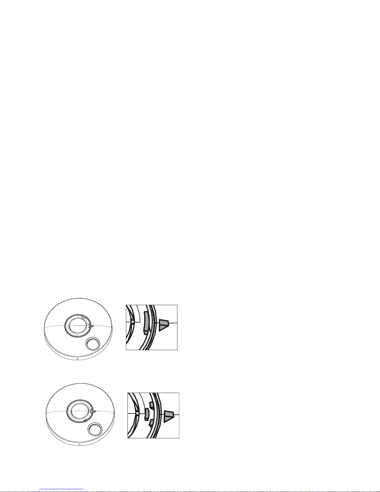
Einstellung für zerstörungsfreie Betätigung des
Notschalters
Einstellung für (die Kappe) zerstörende Betätigung
Besonderheiten beim Terminal-Modul 1370-10
Alle Schalt- und Anzeigefunktionen sind bei den beiden Terminal-Varianten 1337-XX und 1370-10
identisch. Das Terminal-Modul 1370-10 hat jedoch einige mechanische Besonderheiten.
Zerstörungsfreie / zerstörende Betätigung
des Notschalters.
Die rote Abdeckkappe des Notschalters
kann so eingestellt werden, daß sie bei dessen
Betätigung unzerstört bleibt, oder auch so, daß
sie dabei zerstört wird. Werksseitig ist sie auf
eine zerstörungsfreie Notschalterbetätigung
eingestellt.
Zur Umstellung auf eine zerstörende Notschalterbetätigung muß die Notschalterkappe
von hinten mit einem geeigneten Werkzeug –
beispielsweise einem Schraubendreher – aus
der Abdeckhaube herausgedrückt und um 60°
gedreht wieder eingesetzt werden.
Achtung! Beim Herausdrücken und Wiedereinsetzen der Notschalterkappe nur auf
deren Rand einwirken, da sonst das Mittelteil versehentlich herausgebrochen werden
könnte!
Zur genauen Ausrichtung der Notschalterkappe sind auf dieser zwei Markierungen angebracht, die jeweils auf eine Markierung in der
Abdeckhaube ausgerichtet werden müssen.
Öffnen der Abdeckhaube
Die Klarsicht-Abdeckhaube des TerminalModuls1370-10 wird entriegelt indem der
Schlüsselschalter bis zum zweiten Anschlag
entgegen dem Uhrzeigersinn gedreht wird.
Nach Abziehen des Schlüssels kann sie dann
abgenommen werden um beispielsweise den
Notschalter zurückzustellen.
Page 9

9
Alle Funktions- und Zeiteinstellungen am Steuergerät dürfen nur von einer
.
Fachkraft vorgenommen werden!
1.5 Funktionsvarianten
Die Funktionen des Fluchttürsteuergeräts
können über mehrere Dreh- und Schiebeschalter auf der Hauptplatine variiert und damit auf
den jeweiligen Anwendungsfall abgestimmt
werden.
1.5.1 Kurzzeitfreigabe
Die Dauer der Kurzzeitfreigabe kann zwischen 11 und 176 Sekunden in 11-SekundenSchritten eingestellt werden.
Die Kurzzeitfreigabe über den Schlüsseltaster im Türterminal oder Terminal-Modul kann
auch ganz abgeschaltet werden. (Die Kurzzeitfreigabe über den externen Taster ist jedoch
immer möglich.)
1.5.2 Dauerentriegelung
Die Dauerentriegelung über den im Türterminal oder Terminal-Modul integrierten Schlüsseltaster kann abgeschaltet wer den.
Für spezielle Anwendungsfälle, in denen eine versehentliche Auslösung der Dauerentriegelung verhindert werden soll, ist eine Verzögerung der Annahme des Befehls aktivierbar. Er
wird dann nur angenommen, wenn der Schlüssel länger als 5 Sekunden in der linken Schaltstellung gehalten wir d oder die betreffende Taste eines eventuell angeschlossenen Zentraltableaus 725 länger als 5 Sekunden betätigt
wird.
1.5.3 Voralarm
Die Funktion “Voralarm” kann abgeschaltet
werden. Die Dauer des Voralarms ist zwischen
4 und 64 Sekunden einstellbar.
1.5.4 Alarm
Die akustische Signalisierung eines Alarms
durch den im Türterminal bzw. Terminal-Modul
integrierten Summer kann für die Fälle einer
zentralen Alarmauslösung deaktiviert werden.
Bei zentraler Freischaltung und externer Notentriegelung (z.B. Brandmeldezentrale) wird dann
an der Einzeltür kein akustisches Signal gegeben.
Die auf die Einzeltür bezogenen Alarmursachen “Nottaste”, “Rauchmelderlinie” und “Sabotage” werden jedoch immer auch akustisch im
Türterminal und Terminal-Modul signalisiert.
1.5.5 Alarmzeit
Die akustischen Alarmmeldung ist zeitlich
begrenzt. Sie kann auf einen Wert zwischen 11
und 176 Sekunden eingestellt werden.
Page 10
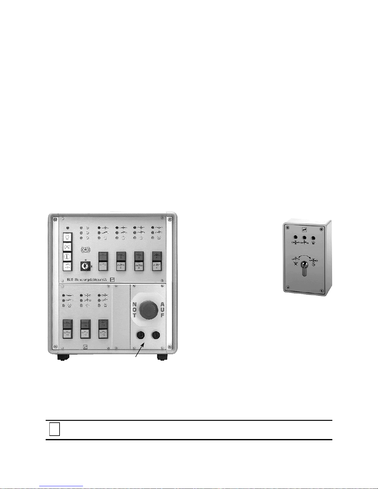
725 NAM-01
10
Abbildung 5: Zentraltableau mit integriertem Not-Auf-Modul
725 NAM-01
Abbildung 6: APBedienteil 1332-10
Alle Funktions- und Zeiteinstellungen am Steuergerät dürfen nur von einer
.
Fachkraft vorgenommen werden!
1.6 Sonderfunktion I: Anlagen mit indirekter Freischaltung. Das Fluchttürsteuergerät 720-32
Die Variante 720-32 des Fluchttürsteuergeräts stellt eine Sonderausführung dar für Fälle, in denen
Fluchttüren von einer zentralen Stelle aus freigeschaltet werden müssen. Sie enthält eine spezielle
Sicherheitsrelaisschaltung, die auch für die Freischaltung mehrerer Türen von einer zentralen Stelle
aus, die für diese Funktion erforder liche Sicherheit bietet.
Alle anderen Funkt ionen des Fluchttürsteuergeräts 720-32 sind identisch mit denen des St euergeräts 720-30.
Anlagen dieser Art werden in erster Linie in Sonderobjekten installiert, wo an den einzelnen Türen
keine Nottaste vorgesehen werden kann. In der Regel muß die zentrale Stelle, von der die Freischaltung der Türen ausgelöst wird, ständig besetzt sein.
Als Schalt- und Anzeigegerät an der Tür dient dann das Bedienteil 1332-10 (Abbildung 3) oder
dessen Unterputz-Version 1332-11. Die Schalt- und Anzeigefunktionen dieser Geräte sind – mit
Ausnahme der fehlenden Nottaste – identisch mi t denen des Türterminals und des Terminal-Modul s.
Zentral-NOT-AUF
Bei der Funktion Zentral-Not-Auf werden Türen
von einer Stelle aus freigeschaltet, die nicht im
unmittelbaren Bereich der betroffenen Türen
liegt. Meist handelt es sich dabei um ein zen-
trales Steuer- und Überwachungstableau, mit
einer Nottaste, die bei Betätigung alle angeschlossenen Türverriegelungen freischal tet.
Alarmrückstellung
Die Rückstellung des
Alarms muß auch bei einer
zentralen Freischaltung an
jeder einzelnen Tür vorgenommen werden.
Dazu muß zunächst die
Nottaste des NOT-AUF-Moduls im Steuerungstableau
wieder herausgezogen werden. Wenn die Nottaste
noch in betätigter Stellung
arretiert ist, ist an der Tür
eine Quittierung des Alarms, mit Abschaltung
des akustischen Signals, jedoch keine Rückstellung möglich.
Abschaltung des akustischen Alarmsignals
Im Fluchttürsteuergerät kann die akustische
Signalisierung eines zent ral ausgelösten Alarms
an der Tür abgeschaltet werden, wenn diese
nicht gewünscht ist.
Page 11

11
1.7 Sonderfunktion II: Betrieb des Fluchttürsteuergeräts mit dem ElektroSicherheitsschloß 809
Das effeff Elektro-Sicherheitsschloß 809 ist ein selbstverriegelndes Panikschloß mit elektrisch
steuerbarem Außendrücker und integri erten Überwachungs- und Schaltkontakt en.
Eine Fluchttürsicherung mit dem Fluchttürsteuergerät 720-30 oder 720-32 kann mit dem effeff
Elektro-Sicherheitsschl oß 809 ( Ausbauver si on mit vi er Über w achungskont akten) kombiniert werden. Mit
dieser G erätekombination können eine Reihe von Funktionen realisiert werden, die insbesondere an
einer Außentür in manchen Anwendungen gefordert sind:
! Die geschlossene Tür ist immer auch mechanisch verschlossen, da das Elektrosicherheits-
schloß eine Selbsverriegel ungsfunktion besitzt, die den Riegel beim Schließen der Tür automatisch vorschließt.
! Die Begehung der Tür von innen ist jederzeit möglich, w ird durch die Fluchttürsicherung jedoch
wirksam überwacht.
! Die Tür kann von außen mit Schlüssel begangen werden, ohne Einsatz eines zusätzlichen
Schlüsselschalters. Diese Funktion wird durch den Profilzylinderkontakt des Elektrosicherheitsschlosses ausgelöst.
! Für die berechtigte Begehung von außen oder von innen, kann die Tür durch Tasterbetätigung
freigegeben werden. Diese Tastfunktion kann von einem Freigabetaster von zentraler Stelle,
von einem Zutrittskontr ollsystem oder ähnlichem gegeben werden.
Begehung der Tür von innen
Die Bedienung einer mit einer solchen Gerätekombination ausgestatteten Tür von innen
unterscheidet sich nicht von der normaler Türen, d i e m i t e l ektr ischer Fluchtt ürsi cherung ausgestattet sind.
Da der Innendrücker des Elektrosicherheitsschlosses Panikfunktion aufweist, wird diese
Begehungsrichtung nur durch die elektrische
Fluchttürsicherung gesteuert. Diese muß also
zunächst durch eine entsprechende Ansteuerung des Fluchttürsteuergeräts, z.B. am Schlüsselschalter des Türt erminals oder Terminal-Moduls, entriegelt oder dur ch einen Gefahrenalarm
(Nottaste, Brandmeldeanlage etc.) freigeschaltet werden, bevor die Tür begangen werden
kann.
Begehung der Tür von außen
Der äußere Drücker des Elektrosicherheitsschlosses ist elektrisch steuerbar. Ohne Ansteuerung befindet er sich im Leerlauf; bei Betätigung bleiben Schloßriegel und Schloßfalle
vorgeschlossen, die Tür kann nicht geöffnet
werden.
Durch elektrische Ansteuerung wird der äußere Drücker des Elektro-Sicherheitsschlosses
auf den Schloßmechanismus aufgekoppelt und
hat dann die gleiche Funktion wie der Innendrücker. Um die Tür von außen begehen zu
können, muß also sowohl das Elektrosicherheitsschloss angesteuert, als auch die Fluchttürsicherung entriegelt werden.
Bei der Kombi nation der beiden Sicherungssysteme werden di ese so miteinander verschaltet, da ß b e i E ntriegelung der Fluchttürsicherung
gleichzeitig über das Fluchttürsteuergerät das
Elektrosicherheitsschoß angesteuer t wird.
Durch einen im Elektro-Sicherheitsschloß integrierten Schaltkontakt, der vom Profilzylinder
betätigt wird, kann andererseits eine Kurzzeitfreigabe der Fluchttürsicherung ausgelöst werden. Damit kann die Tür von außen mit Schlüssel jederzeit begangen werden. Ein zusätzlicher
Schlüsselschalter ist nicht erforderlich. Wird die
Tür geöffnet und wieder geschlossen, ist sie
wieder durch beide Systeme gesichert, wobei
die mechanische Verriegelung durch das Elektrosicherheitsschloß auch bei einem Totalausfall der Energieversorgung erhalten bleibt.
Page 12
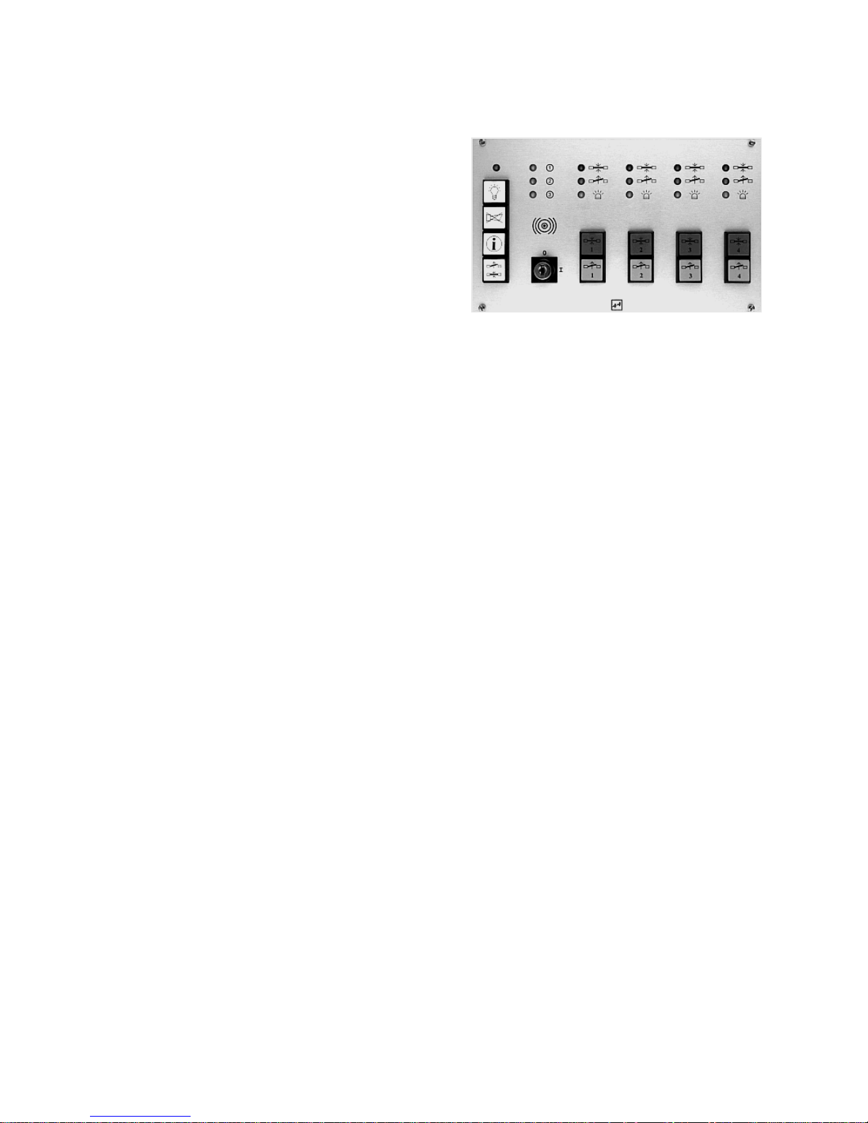
12
Abbildung 7: Hauptmodul des Bus-Steuerungstableaus
925 mit vier Türsteuereinheiten.
1.8 Sonderfunktion III: Betrieb am effeff-Türsteuerbus mit Steuerungstableau
925
Die mit einer Fluchttürsicherung mit dem Fluchttürsteu
ergerät 720-30 oder 720-32 überwachten und gesteuerten Türen können bei Bedarf auf einem zentralen
Anzeige- und Bedientableau zusammengeführt werden.
Die betriebsmäßige Steuerung der Türen erfolgt
dann über die im Tableau integrierten Taster. Die Anzeige des Zustandes jeder einzelnen T ür wird – analog
der optischen Anzeige am Türterminal – durch drei
LEDs dargestellt.
Dabei bleiben alle Funktionen des Fluchttürsteuergerätes, einschließlich der Schalt- und Anzeigefunktionen
des Türterminals oder Terminal-Moduls, wie beschrieben, erhalten.
Details zu Funktion und Bedienung des Zentraltableaus “Bus-Steuerungstableau 925"sind in
einer eigenen Bedienungsanleitung zu diesem Tableau aufgeführt.
Page 13

Die Zahlen in dieser Spalte beziehen sich auf die Abschnitte des folgenden Kapitels.
1
13
1.9 Ermittlung einer Alarmbedingung
Am Türte rminal1337-xx sowie am Terminal-Modul1370-10 besteht die Möglichkeit, die Ursache für
einen Alarm festzustel len solange sie noch besteht.
Dazu muß folgendermaßen vorgegangen werden. Zuerst muß der Al arm quittiert werden, indem am
Schlüsselschalter des Terminals nach links getastet wird. Wenn das Alarmkriterium noch ansteht,
beginnt die grüne LED nun zu blinken; die gelbe LED erlischt. Anschließend den internen Schlüsseltaster zuerst nach links drehen, halten, und die Anzeige im Steuerterminal beachten. Der gleiche
Vorgang ist bei der Schlüsseldrehung nach rechts zu wiederholen. Aus den Anzeigen am Steuerterminal kann aus nachfolgender Tabelle die Ursache des Alarms ermittelt werden. Nachdem diese
beseitigt ist, kann am Schlüsselschalter die Tür wieder verriegelt, also das System wieder in seinen
Grundzustand geschaltet werden.
Tabelle zur Ermittlung der Alarmbedingung:
Auslösekriterium Schlüsselschalter betätigt nach:
Links Rechts
Klem-
me
LED rot grün gelb rot grün gelb
1
Sabotage am Terminal 2
oder Bedienteil
Ç
Sabotage der Tür (*)
32
È
Not-Auf
(es war entriegelt)
É
Not-Auf
(es war verriegelt)
Ê
Zentral-Not-Auf
(720-32)
(es war entriegelt)
Ë
Zentral-Not-Auf
(720-32)
(es war verriegelt)
Ì
Verriegelungsrückmel- 15
dung fehlt
Í
Externe Notentriegelung. 17
(Brandmeldeanlage)
Î
Rauchmelderlinie 45-46 Ï
D0019203T0000200
(*) In diesem Fall blinkt die grüne LED nach Quittierung des Alarms nicht. Wenn der Türkontakt jedoch weiterhin geöffnet ist,
wird ein Verriegelungsbefehl nicht angenommen.
Das gleiche gilt, wenn ein Tür-offen-Alarm ausgelöst wurde, weil nach einer Kurzzeitfreigabe die Tür zu lange offen blieb.
Bei Ausfall der Netzspannung und Umschaltung auf Akkubetrieb, beginnt die gelbe LED zu
blinken und das Relais für externe Alarmierung zieht an. Die Tür bleibt verriegelt.
Quittierung des Alarms löscht die externe Signalisierung. Am Terminal bleiben jedoch alle
Schalt- und Anzeigefunktionen erhalten. Die gelbe LED blinkt jedoch ständig bis zur Wiederkehr
der Netzspannung.
Page 14

14
1.10 Beseitigung der Alarmursachen
Ç Sabotage am Steuergerät, Ter m inal- oder Bedienteil
Überprüfen Sie, ob bei allen Geräten die Deckel geschlossen sind bzw. das Oberteil richtig im Innengehäuse eingerastet und mit diesem gegebenenfalls verschraubt ist!
È Sabotage der Tür (*)
Überprüfen Sie die Tür und die korrekte Montage des Tür- bzw. Rückmeldekontaktes. Wenn die Tür
nicht sabotiert wurde, muß beim Fluchttüröffner eventuell der Fallenausschluß des Gegenstücks
vergrößert werden.
É Ê Not-Auf
Zur Rüc kstellung des Notschalters muß die Abdeckhaube abgenommen werden. Beim Türterminal
kann sie einfach abgenommen werden.Beim Terminal-Modul wird sie aus ihrer Verankerung gelöst,
indem der Schlüsselschalter bis zum zweiten Anschlag entgegen dem Uhrzeigersinn gedreht wird.
Der Betätigungspilz des Notschalters wird beim Türterminal ebenfalls einfach herausgezogen. Beim
Terminal-Modul muß er durch eine leichte Drehung nach links oder rechts zurückgestellt werden.
Danach kann mit dem Schlüsselschalter der gewünschte Schaltzustand wiederhergestellt werden.
Beim Terminal-Modul muß vor dem Wiedereinsetzen der Abdeckhaube bei zerstörender Einstellung der
Notschalterkappe diese noch erneuert werden. (Siehe Seite 8.)
Ë Ì Zentral-Not-Auf
Es muß zunächst der zentrale Not-Auf-Schalter zurückgestellt werden. Nach dem Rückstellen können
die einzelnen Türen wieder in den gewünschten Zustand geschaltet werden.
Í Verriegelungsrückmeldung fehlt
Diese Meldung kann beispielsweise entstehen, wenn die Tür nicht vollständig geschlossen ist, so daß
beim Flächenhaftmagneten die Haftgegenplatte nicht an der Polfläche anliegt bzw. der Fluchttüröffner
nicht verriegeln kann weil eventuell eine kräftige Türdichtung seine Falle ein wenig aufdrückt. Sorgen
Sie dafür, daß die Tür richtig schließen kann.(Eventuell muß der Türschließer neu eingestellt werden.)
Beim Flächenhaftmagneten dürfen keine Fremdpartikel das Anliegen der Haftgegenplatte an der
Polfläche behindern.
Î Externe Notentriegelung. (Brandmeldeanlage)
Nach der Quittierung des Alarms muß zunächst der externe Kontakt zurückgestellt (wieder geschlossen) werden. Danach kann am Steuerterminal mit dem Schlüsselschalter der gewünschte Schaltzustand wieder hergestellt werden.
Ï Rauchmelderlinie
Wenn ein Rauchmelder ausgelöst hat, muß am Schlüsselschalter des Terminals zweimal nach links
getastet werden. Nach dem zweiten Tastimpuls wird nach einer Verzögerungszeit von ca 7 Sekunden
der Melder zurückgesetzt und die Melderschleife wieder scharf geschaltet. (Vorausgesetzt, der Melder
ist inzwischen rauchfrei.)
Beachten Sie, daß die meisten Alarmmeldungen auch durch eine Leitungsunterbrechung – al so
beispielsweise einen Kabelbruch – ausgelöst werden können. Führt also eine Überprüfung und
Behebung der oben aufgeführten Kriter i en nicht zu einer Aufhebung des Alarmzustandes, ist die
Installation vom Fachmann zu überprüfen!
Page 15

15
Achtung!
Für die Installation und den Betrieb von elektrischen Verriegelungen von Türen in
Rettungswegen sind baurechtliche Bestimmungen zu beachten!
Die Geräte entsprechen den in der Europäischen Union geltenden Richtlinien bezüglich
elektromagnetischer Verträglichkeit (EMV).
Bei der Elektroinstallation sind die VDE-Vorschriften sowie die Bestimmungen der örtlichen
EVUs zu beachten.
Achtung!
An Rauchschutztüren oder Feuerschutztüren dürfen elektrische Verriegelungssysteme nur
wenn der Verwendbarkeitsnachweis für die betreffende Tür dies vorsi eht und nur nach dessen
Maßgabe angebracht werden. Ausnahme: Elemente, die auch an bereits hergestellten
Feuerschutzabschlüssen angebracht werden dürfen.
Die Übereinstimmung der Gerä te mit der “Richtlinie über elektrische Verriegelungssysteme von
Türen in Rettungswegen (EltVTR)” (Bauregelliste A Teil 1, lfd. Nr. 6.19) ist geprüft vom TÜV
Rheinland, Köln.
Nr. des Prüfzertifikats: R 9910839
2 Installation
Page 16
225,5
300
186
125
16
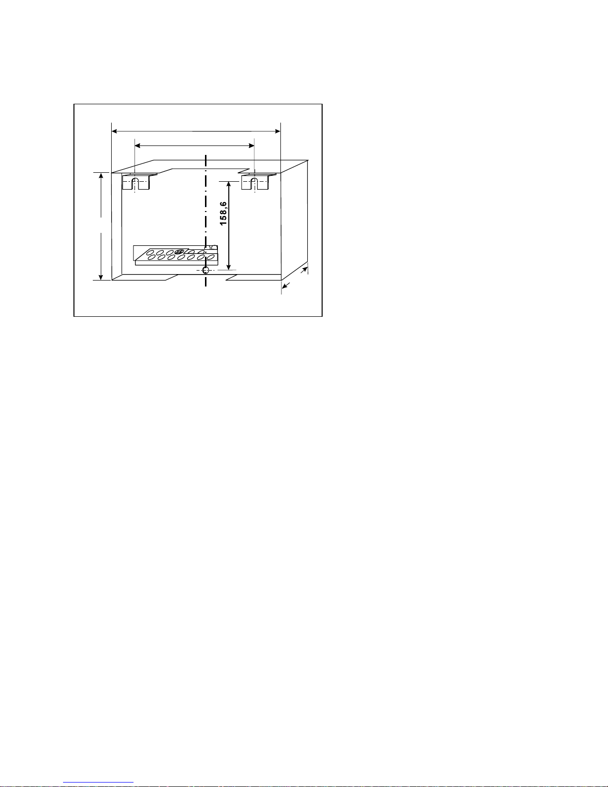
Abbildung 8: Montageskizze D0019203G0000100
2.1 Montage des Steuergeräts
Das Gehäuse des Steuergeräts ist für
Wandmontage vorgerichtet.
Es wird an zwei Sc h r a uben mit Durchmesser
4,5 mm an den Montagewinkeln eingehängt
und mit einer dritten Schraube, die durch die
untere, mittige Bohrung in der GehäuseRückwand geschraubt wird, fixiert.
Aufputz verlegte Kabel können von oben
oder von unten zur Kabeleinführung geführt
werden.
Der Montageort des Steuergeräts darf
nicht direkter Sonnenei nstrahlung ausgesetzt sein.
Bei Montage in einer Zwischendecke ist
auf die Einhaltung der zulässigen Umgebungsbedingungen gemäß technischen
Daten S 41 zu achten!
Page 17

17
Es ist auf Einhaltung der einschlägigen VDE-Vorschriften sowie der Bestimmungen des
örtlichen EVUs zu achten.
2.2 Allgemeine Hinweise zur elektrischen Installation
Achtung:
Auf richt igen Anschluß achten! Bei falschem Anschluß keine Garantieleistung.
Zulässige Belastung des Netzteils des Steuergeräts mit externen Geräten 24 V DC: max 1,1 A
Tabelle 3: Stromaufnahme typischer, an das Steuergerät anschließbarer Geräte
Haftmagnet Modell 828 315 mA
Fluchttüröffner Modell 331 RR AKRR 160 mA
Pendeltüröffner 351 AKRR 160 mA
Haftmagnet Modell 827 250 mA
Türterminal Modell 1337-10/11 60 mA
Terminal-Modul 1370-10 60 mA
Bedienteil Modell 1332-10/11 50 mA
Blitzlampe Model l 1055-24 250 mA
Piezohorn Modell 1037-10 20 mA
Rauchmelder Modell 60030 3 mA
D0019203T0000300
EMV-Schutz:
! Es sind abgeschirmte Leitungen zu verwenden. Alle Kabelschirme müssen einseitig auf
die dafür im Gehäuse des Steuergerät s vorgesehene Erdungsschiene aufgelegt werden
Steuerleitungen:
! Länge max. 300m, Mindestdurchmesser 0,6mm.
Leitungen zum Verriegelungselement:
! Länge max. 300m.
! Der Querschnitt der Leitung ist so zu bemessen, daß am bestromten Verriegelungs-
element eine Spannung von 24V ansteht.
! Eine Anhebung der Ausgangsspannung um ca. +10% (lastabhängig) ist zum Ausgleich
von Leitungsverlusten am Pot entiometer PO1 einstellbar.
Alle in den Anschlußplänen gestrichelt gezeichneten Steuer- und Anzeigeelemente und Leitungen sind optional anzuschließen.
Page 18
720-30
230 V ± 10%
L N PE
6
16
Türterminal
oder
Terminal-Modul
Ò
Fluchttürsteuergerät
Türsteuerungstableau 925 (Bus-Technik)
Zentraltableau 725
Ext. Notentriegelung
(z.B. Brandmeldeanlage)
Bedienteil 1332-10/11
2
8
2
10
2
2
2
Schaltuhr
Externer Taster Kurzzeitfreigabe
Rauchmelder
Ñ
Verriegelungselement
(Modell 331 RR AKRR mit Gegenstück Modell 807-10
oder Modell 351 RR AKRR)
18
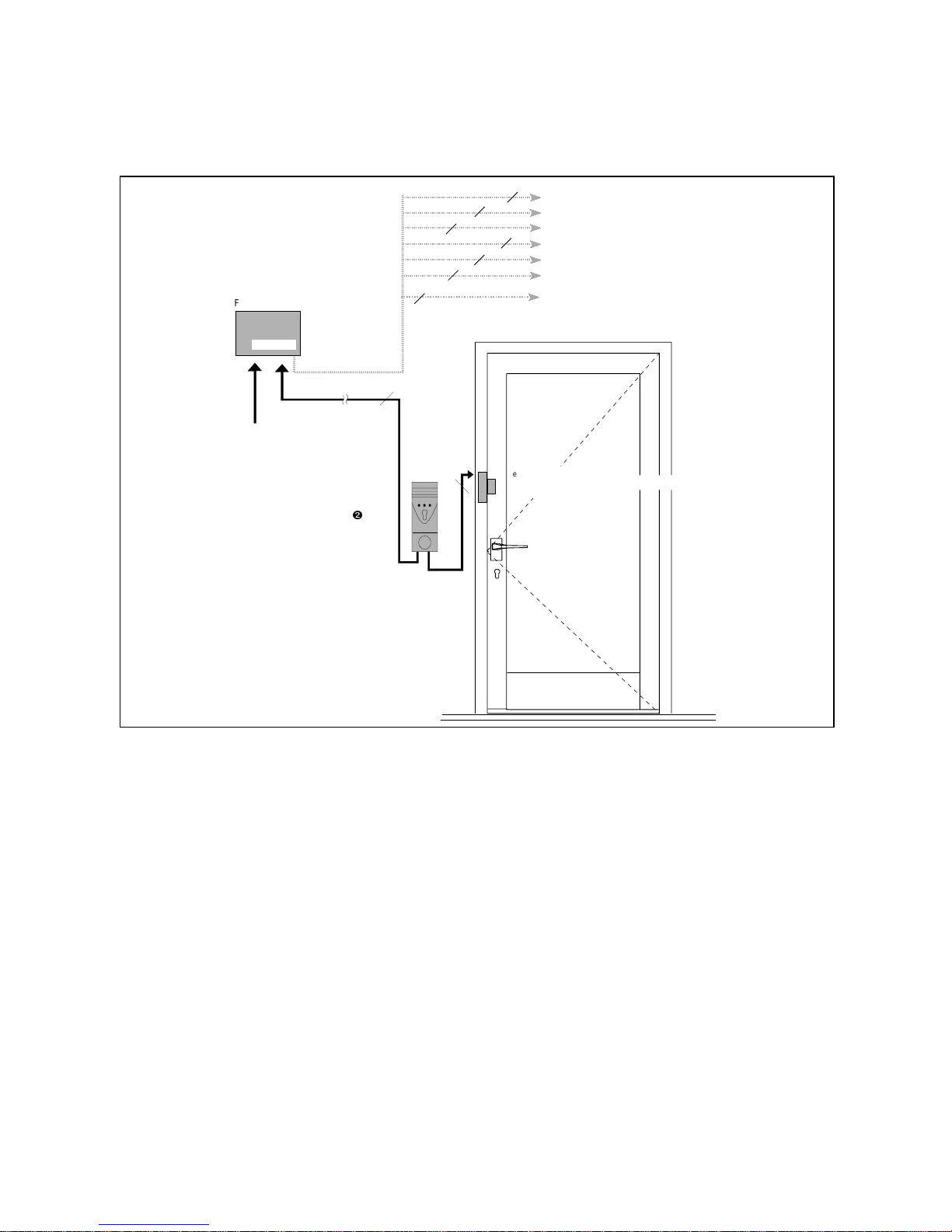
Abbildung 9: Skizze Verkabelung einflügelige Fluchttür mit Flucht- oder Pendeltüröffner D0019203G0000200
2.3 Kabelpläne und Anschlußdetails
2.3.1 Fluchttürsicherung für eine einflügelige Fluchttür (Kabelplan)
Ñ Die Verriegelungselemente 331 oder 351 werden üblicherweise, wie in der Skizze dargestellt,
möglichst nahe beim Schloß eingesetz t, um Hebelkräfte so gering wie mögl ich zu halten.
Flächenhaftmagnete werden oben quer eingesetzt. Dabei muß auf die Einhaltung der minimalen
lichten Durchgangshöhe von 2000 mm geachtet werden.
Ò Der Verkabelungsplan ist für beide Terminal varianten gleich.
Page 19
19
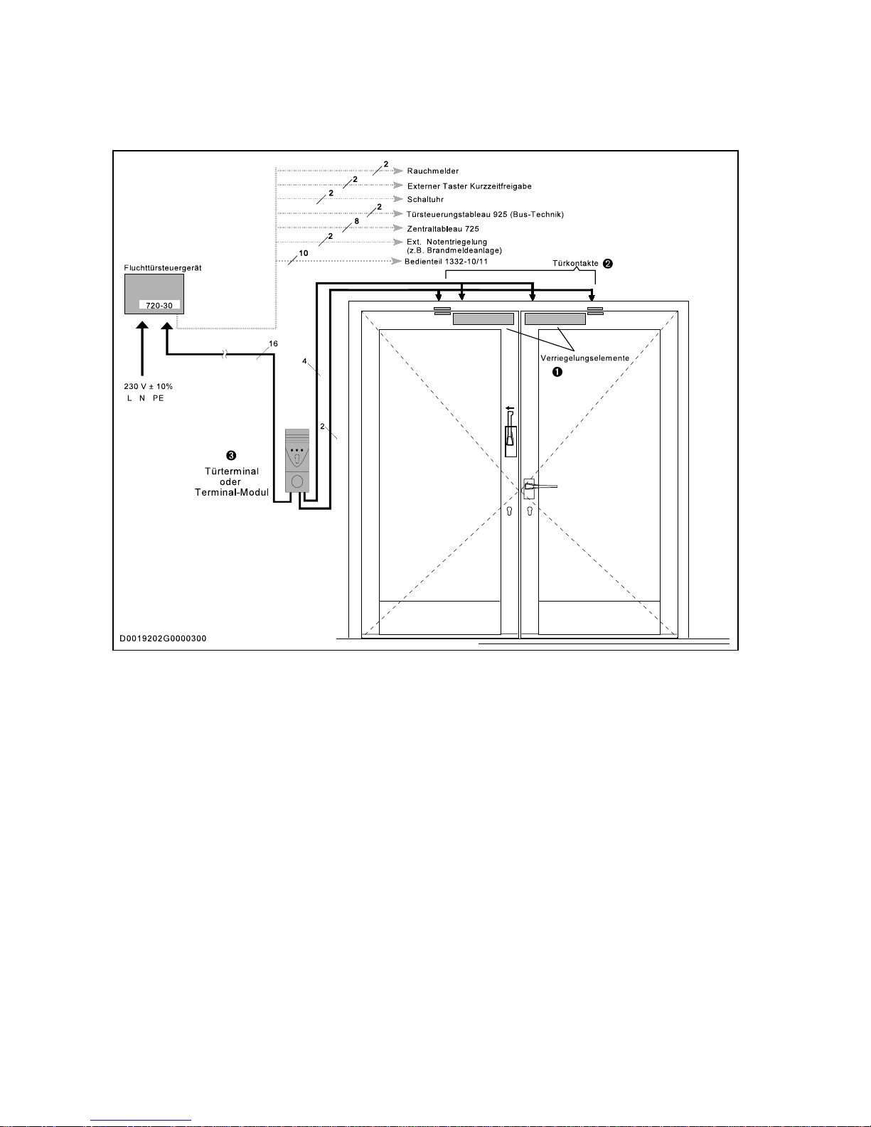
Abbildung 10: Skizze Verkabelung zweiflügelige Fluchttür mit Flächenhaftmagnet D0019203G0000300
2.3.2 Fluchttürsicherung für eine zweiflügelige Fluchttür (Kabelplan)
Ñ An zweiflügeligen Türen ist pro Flügel ein Verriegelungselement einzusetzen. Es können alle
Fluchtür-Verriegelungsel emente aus dem effeff-Programm eingesetzt werden.
Bei Verwendung der Flächenhaftmagnete muß auf Einhaltung der minimalen lichten Durchgangshöhe von 2000 mm geachtet werden!
Ò Bei Verwendung des Fluchttüröffners 331 RR AKRR oder des Pendeltüröffners 351 RR AKRR
entfällt der Einbau von Türkontakt en, da diese bereits im Türöffner integr iert sind.
Ó Der Verkabelungsplan ist für beide Terminal varianten gleich.
Page 20
=
F 1
0,5 A T
F 2
2 A T
F 3
1,25 A T
F 6
1,25 A T
F 5
1,25 A T
rot
rot-schwarz
rot-schwarz
rot
L 1
N
PE
Netzzuleitung
L 1, N, PE;
3 x 1,5 mm
2
AK 1
AK 2
Akku 1
12 V / 2 Ah
Akku 2
12 V / 2 Ah
PO 1
Einstellbereich
Ausgangsspannung
24 V + 10%
PO 2
AkkuLadespannung
LED “NT”
(grün)
LED “AK”
gelb
Ñ
Ò
Ó
Ô
Õ
Ö
F 7
0,1 A T
F 4
1,25 A T
Zum Anschluß der Netzleitung:
Zur Einhaltung der Niederspannungsrichtlinie (DIN-EN 60950) ist folgendes beim Anschluß der Netzleitung
zu beachten:
1. Netzleitung ca. 15 cm abmanteln.
2. Schwarze und blaue Ader auf ca. 3 cm kürzen.
3. Alle drei Adern ca. 8 mm abisolieren.
4. Schwarze Ader auf Klemme “L” und blaue Ader
auf Klemme “N” führen und unterklemmen. Dabei
Mantel dicht an Klemmen heranführen.
5. Grün-gelbe Ader umbiegen, auf Erdungsschiene
führen und anklemmen.
6. Mit Kabelbinder die drei Adern möglichst nahe
den Klemmen fassen und binden.
20
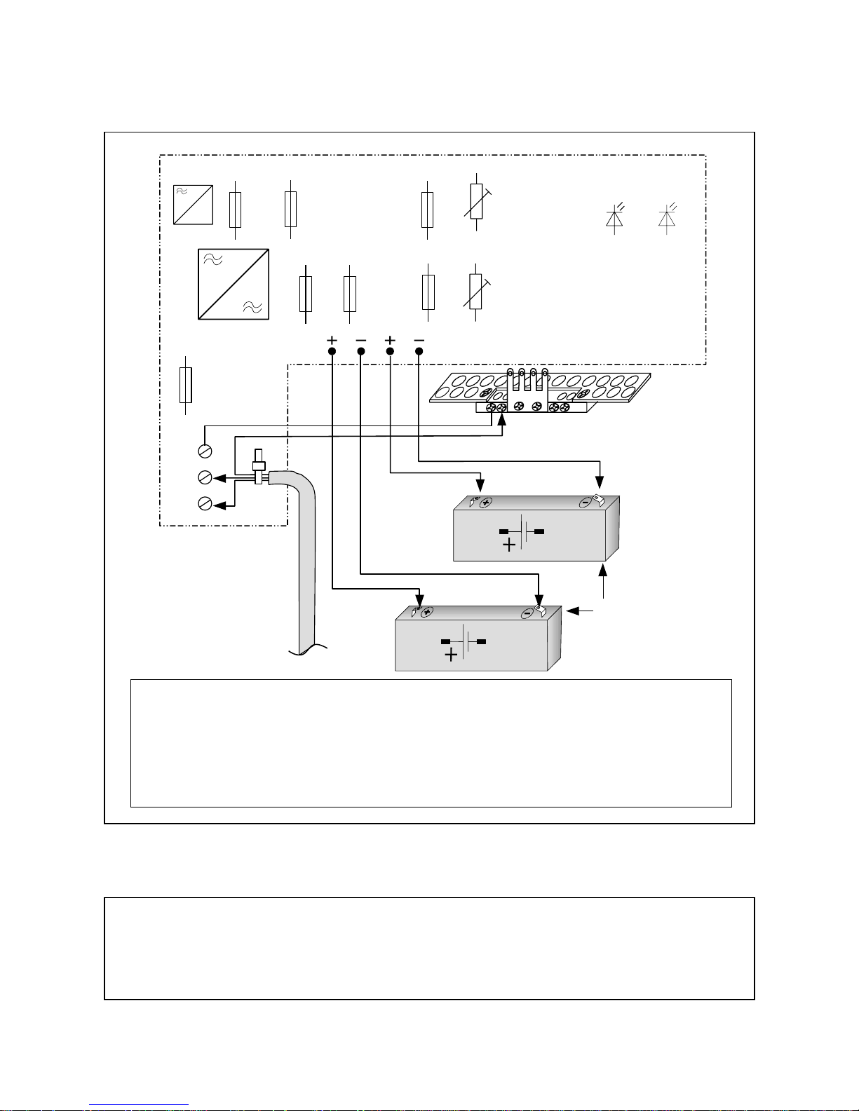
Abbildung 11: Detailskizze Netz- und Akkuanschluß D0019203A0000100
Achtung!
Bei Versorgung des Geräts mit externer Spannung über die Klemmen 25-26 darf keine
Netzzuleitung angeschlossen sein! – Akkus dürfen dann nicht angeschlossen werden! –
Schalter S 5.6 muß in Stellung “of f” stehen! Nas Netzteil muß DIN EN 60950 ent sprechen!
Eigen-Stromaufnahme der Steuerung: 150 mA.
2.3.3 Netz- und Akkuanschluß
Page 21

21
Anmerkungen zu Seite 20
Ñ Netzanschluß und Kabelführung
Alle Anschlüsse sollen so kurz wie möglich gehalten werden. Der Schutzleiter muß auf die Erdungsschiene des Gehäuses
aufgelegt werden. Die Verbindung zwischen der Erdungsschiene und PE ist bereits werksseitig hergestellt.
Das Gerät muß durch eine leicht zugängliche Trennvorrichtung vom Versorgungsstromkreis getrennt werden
können.
Ò Potentiometer PO 1
Mit PO 1 kann die Ausgangsspannung für das Verriegelungselement nachgeregelt werden. Dies kann in den Fällen erforderlich werden, wo es, bedingt durch größere Leitungslängen zwischen Steuergerät und Verriegelungselement, zu
nennenswerten Leitungsverlusten kommt. Die Spannung muß in einem solchen Fall so nachgeregelt werden, daß an den
Klemmen des bestromten Verriegelungselements 24 Volt anliegen.
Ó Potentiometer PO 2
Mit PO 2 wird die Akku-Ladespannung eingestellt. Diese ist werksseitig bei jedem Gerät bereits genau eingestellt.
PO 2 darf in keinem Fall verstellt werden!
Ô Akkus 12 V, 2 Ah
Das Gerät kann auch ohne Akkus betrieben werden. Wenn jedoch Akkus angeschlossen werden, dürfen nur die von effeff
unter der Bestellnummer 18002 angebotenen Bleiakkus 12 V, 2 Ah angeschlossen werden.
Die Akkus werden im Raum vor den Anschlußklemmen waagrecht auf den Gehäuseboden gestellt.
Die Akkus sind in regelmäßigen Abständen durch einen 15-minütiger Notstrombetrieb zu überprüfen. Nach W iedereinschalten der Netzspannung muß das Steuergerät den Betriebszustand I gemäß Tabelle 4 einnehmen. Wird einer der
Betriebszustände II oder III eingenommen, müssen die Akkus ausgetauscht werden.
Bei Akku-W echsel oder -Neuanschluß kann der Beriebszustand III gemäß Tabelle 4 eingenommen werden. W echselt die
Anzeige nicht innerhalb drei Sekunden zu Betriebszustand II oder I, ist das Gerät kurzzeitig vom Netz zu trennen und wieder
einzusc h a l t e n. Danach muß innerhalb von 10 Minuten Betriebszustand II oder I erreicht werden. Geschieht dies nicht, sind
die angeschlossenen Akkus defekt.
Õ LED-Anzeigen auf Platine:
LED “NT” LED “AK” Betriebszustand Bemerkungen
grün gelb
EIN AUS Akku innerhalb von 24 Stunden auf 80%
(I) Netzbetrieb. U > Entladeschlußspan-
Akkus
nung
Nach Erlöschen der gelben LED wird der
seiner Nennkapazität aufgeladen.
EIN Die Akkus werden geladen.
langsam
blinkend 1:1
(II) Netzbetrieb. 12 V < U < Entlade-
Akkus
schlußspannung
EIN EIN (III) Netzbetrieb. U < 12 V oder fehlend
Akkus
Die Akkus sind tiefentladen, defekt oder
nicht angeschlossen.
AUS blitzend kungszeit von mindestens 15 Min. garan-
(IV) Akkubetrieb (Netzausfall bei vorhande-
nen Akkus)
Bei geladenen Akkus wird eine Überbrük-
tiert.
AUS AUS
(V) externe 24 V -Versorgung (kein Netz, kei-
ne Akkus)
S 5.6 muß in Stellung “off” stehen. (Siehe
S. 36)
EIN
schnell blin-
kend 1:1
(VI) Kurzschluß auf Akkuklemmen
Tabelle 4: LED-Anzeige auf Hauptplatine
D0019203T0000400
Ö Erdungsschiene im Gehäuse
Im Gehäuse befindet sich, direkt unter der Kabeleinführungsöffnung, fest mit dem Kabelbefestigungssteg verbunden, die
Erdungsschiene. Sie ist werkseitig bereits mit der PE-Klemme verbunden. Der Schutzleiter der Netzzuleitung muß auf die
zweite Schraubklemme der Erdungsschiene aufgelegt werden.
Auf diese Erdungsschiene sind die Kabelschirme aller ankommenden Leitungen aufzulegen!
Sicherungen:
F 1 Primärsicherung Transformator 0,5 AT F 4 Eingangssicherung externe Stromversorgung (Klem-
F 2 Sekundärsicherung Transformator 2 AT F 5, F 6 Akkusicherungen 1,25 AT
F 3 Eingangsicherung Steuerteil 720-30/32 1,25 AT
men 25-26) 1,25 AT
F 7 Versorgung Auswerteelektronik Haftmagnet (Klemme
14) 0,1 AT
Page 22
12 14 19 20 21 22
1
23 4
56
78 9
10 11 12131415 313247 48
12345678910 111315161718
1310 7 9 11 14 4 6 5 2 3116 17
Summer
rt gn
ge
rt
gn ge
Bedienteil 1332-10/11
Türterminal 1337-10/11
Fluchttürsteuergerät 720-30/32
Anschluß Verriegelungselement
Siehe Gesamtanschlußplan
720-30 720-32
22
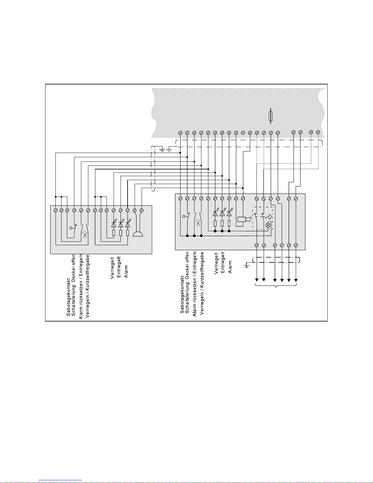
Abbildung 12: Anschlußdetail Türterminal und Bedienteil D0019203A0000200
2.4 Verriegelungssy steme mit dem Türterminal 1337- 10/11
2.4.1 Anschlußdetail paralleler A nschluß Bedienteil 1332 und Türter minal 1337-10/11
Page 23
23
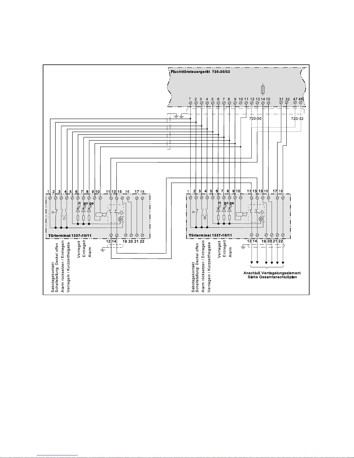
Abbildung 13: Parallelschaltung zweier Türterminals D0019203A0000300
2.4.2 Anschlußdetail: Paralleler Anschluß von zwei Türterminals 1337-10/11
Page 24
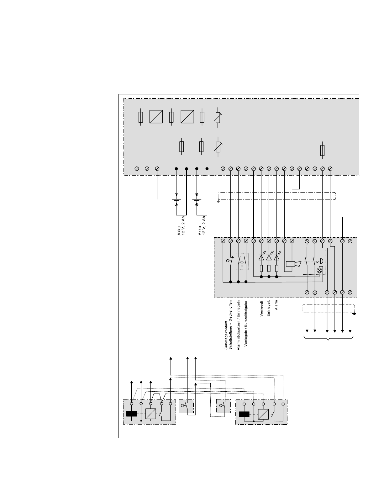
+
+
+
=
F1
0,5AT
F2
2AT
F3
1,25AT
F7
0,1AT
F5
1,25AT
F6
1,25AT
AK1 AK2
+-+-
123456789101112131415
Einstellbereich
Ausgangsspannung
24V +10%
AkkuLadespannung
(sie he Bedienungsanleitung )
++
PO1
PO2
rt
gn ge
12345678910
11 13
15 16
17 18
12
14
19 20 21 22
Türter minal 133 7.10/11
Achtung!
Wenn zwei Verriegelungselemente auf
das Steuergerät aufgeschaltet werden,
(z.B. bei zweiflügeligen Türen) müssen
sowohl die Türkontakte, als auch die
Verriegelungsüberwachungen
(Ankerkontakt bzw. Hallelement) in Reih
e
geschaltet werden.
Anschluß des Verriegelungsteils
siehe unten!
Haftmagnet Modell 828 24 V
Haftmagnet Modell 828 24 V
Türkontakt
Türkontakt
56432
56432
A
B
D
E
F
C
A
BD
E
F
C
Netzspannung
230 V / 50-60 Hz
L1 N PE
L1 N PE
24
2.4.3 Gesamtanschlußplan 720-30 mit Türterminal 1337-10/11
Page 25

F4
1,25AT
+
-
S1 S2 S3 S6S4 S5 S7
(Schalterbelegung und Einstellung si ehe Bedienungsanleitung)
16 17 18 19 20 21 22 23 24 25 26 27 28 29 30 31 32 33 34 35 36 37 38 39 40 41 42 43 44 45 46 47 48 A B
+UB
rt
gn ge
Zentraltableau 725......
Relais - 5
max. 24V / 1A
Relais - 4
Alarmrelais
max. 24V / 1A
Melder-1
Melder-..n
2,43K
BM
BM
Brandmelderschleife
LED “NT”
grün
2,43 K
Fluchttürsteuergerät 720-30
ge
gn br
ws ge
gn br
ws
ABD EF
Türkontakt
Haftmagnet
Modell 827 24 V
Haftmagnet
Modell 827 24 V
Pendeltür öff ner Modell 351 R R AKRR 24 V
Ankerkontakt Türkontakt
(RR-Kontakt)
AB DEF
blgnrt
rt
bl
gn
rt
Fluchttüröffner Modell 331 RR AKRR 24 V
AB DE F
Spule
Ankerkontakt
Rückmeldekontakt
rt
bl
gn
bl rt gn
bl rt
LED “AK”
gelb
74568321
Busanschluß
effeff TS-Bus
25
D0019203A0000400
Page 26
rt gn
ge
3
1
2
SK
J1
789101112
123456
Terminal-Modul 1370-10
16
23 17
18 221920 21 14
13
1
2 3 4 5 6 7 8 9 10 11 12 1314 15 31 32 47 48
13 10 7 9 11 14 4 6 5 2 3116 17
Summer
Bedienteil 1332-10/11
Fluchttürsteuergerät 720-30/32
Anschluß Verriegelungselement
Siehe Gesamtanschlußplan
720-30 720-32
ABCDE F
rt
gn
ge
26
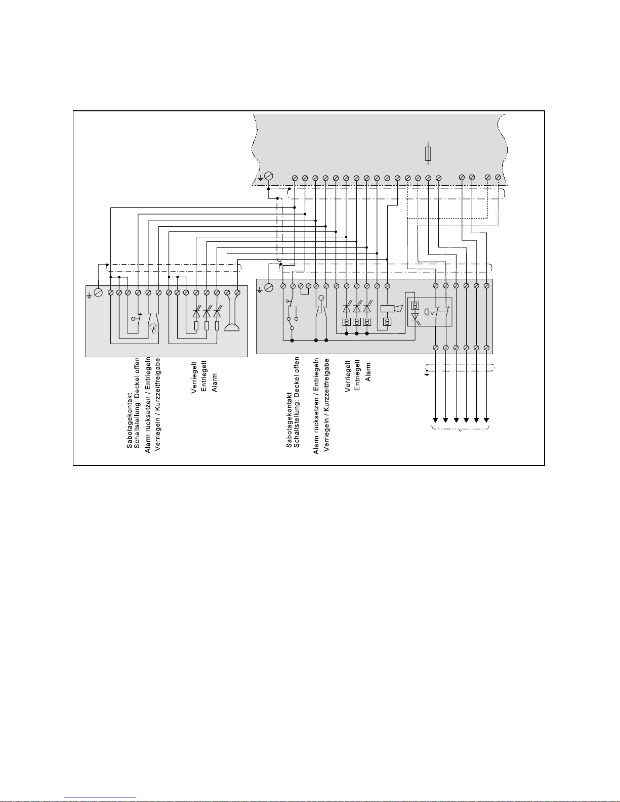
Abbildung 14: Anschlußdetail Terminal-Modul und Bedienteil D0019203A0000500
2.5 Verriegelungssy steme mit dem Terminal-Modul 1370-10
2.5.1 Anschlußdetail: Terminal-Modul 1370-10 mit Bedienteil 1332
Ñ Steuergerät und Terminal-Modul müssen über die Kabelschirme miteinander verbunden werden.
Diese dürfen jedoch nur einseitig (am Steuergerät) geerdet wer den.
Ò Die Abschirmungen aller am Steuer gerät ankommenden Leitungen sind dort auf die Erdungsschiene
aufzulegen. Sie dürfen nur einseitig geerdet werden.
Ó Jumper J1
Der Sabotagekontakt des Terminal-Moduls kann mit Hilfe des Jumpers J1 als Schließer oder Öffner
eingestellt werden. Beim Steuergerät 720-30 muß er als Schli eßer eingestellt sein.
Er muß deshalb auf die Position 2-3 umgestekt werden. Achtung! Der Auslieferungszustand ist
Position 2-1!
Page 27

rt gn
ge
3
1
2
SK
789101112
123456
Türterminal 1370-10
16
23 17
18 221920 21 14
13
Anschluß Verriegelungselement
Siehe Gesamtanschlußplan
ABCDE F
J1
1
2 3 4 5 6 7 8 9 10 11 12 1314 15 31 32 47 48
rt gn
ge
3
1
2
SK
789101112
123 456
Türterminal 1370-10
16
23 17
18 221920 21 14
13
J1
Fluchttürsteuergerät 720-30/32
720-30 720-32
27
Abbildung 15: Anschlußdetail 2 Terminal-Module D0019203A0000600
2.5.2 Anschlußdetail paralleler Anschluß zweier Terminal-Module 1370-10
Steuergerät und Terminal-Modul müssen über die Kabelschirme miteinander verbunden werden. Di ese
dürfen jedoch nur einseitig (am Steuergerät) geerdet werden.
Die Abs chirmungen aller am Steuergerät ankommenden Leitungen sind dort auf die Erdungsschiene
aufzulegen. Sie dürfen nur einseitig geerdet werden.
Jumper J1
Der Sabotagekontakt des Terminal-Moduls kann mit Hilfe des Jumpers J1 als Schließer oder Öffner
eingestellt werden. Beim Steuergerät 720-30 muß er als Schli eßer eingestellt sein.
Er muß deshalb auf die Position 2-3 umgestekt werden. Achtung! Der Auslieferungszustand ist
Position 2-1!
Page 28
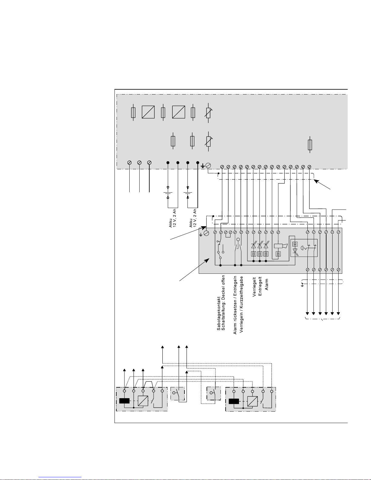
+
+
+
=
F1
0,5AT
F2
2AT
F3
1,25AT
F7
0,1AT
F5
1,25AT
F6
1,25AT
AK1 AK2
+-+-
12 13 14 15
Einstellbereich
Ausgangsspannung
24V +10%
AkkuLadespannung
(siehe Bedienungsanleitung)
++
PO1
PO2
Achtung!
Wenn zwei Verriegelungselemente auf
das Steuergerät aufgeschaltet werden,
(z.B. bei zweiflügeligen Türen) müssen
sowohl die Türkontakte, als auch die
Verriegelungsüberwachungen
(Ankerkontakt bzw. Hallelement) in Reihe
geschaltet werden.
Haftmagnet Modell 828 24 V
Haftmagnet Modell 828 24 V
Türkontakt
Türkontakt
56432
56432
A
B
D
E
F
C
Netzspannung
230 V / 50-60 Hz
L1 N PE
L1 N PE
rt
gn
ge
3
1
2
SK
J1
789101112
Terminal-Modul 1370-10
16
23 17
18
221920 21 14
13
1
23 4
56
78 9
10 11 12131415
Anschluß Verriegelungseleme
nt
ABCDEF
123 456
Ñ
Ò
Ó
28
Ñ Steuergerät und Ter-
minal-Modul müssen
über die Kabelschirme
miteinander verbunden
werden. Diese dürfen
jedoch nur einseitig
(am Steuergerät) geerdet werden.
Ò Die Abschirmungen
aller am Steuergerät
ankommenden Leitungen sind dort auf die
Erdungsschiene aufzulegen. Sie dürfen nur
einseitig geerdet werden.
Ó Jumper J1
Der Sabotagekontakt
des Terminal-Moduls
kann mit Hilfe des Jumpers J1 als Schließer
oder Öffner eingestellt
werden. Beim Steuergerät 720-30 muß er
als Schließer eingestellt
sein.
Er muß deshalb auf
die Position 2-3 umgestekt werden.
Achtung! Der Auslieferungszustand ist
Position 2-1!
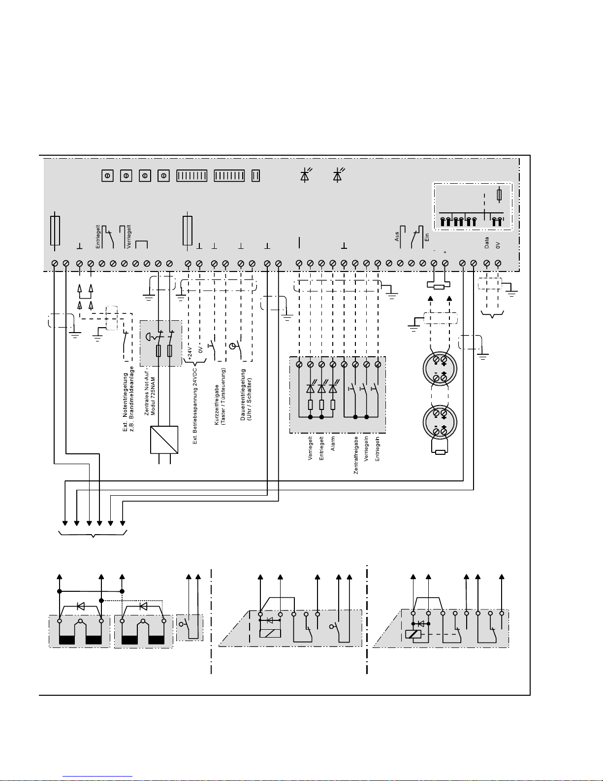
2.5.3 Gesamtanschlußplan 720-30 mit Ter m inal-Modul 1370-10
Page 29
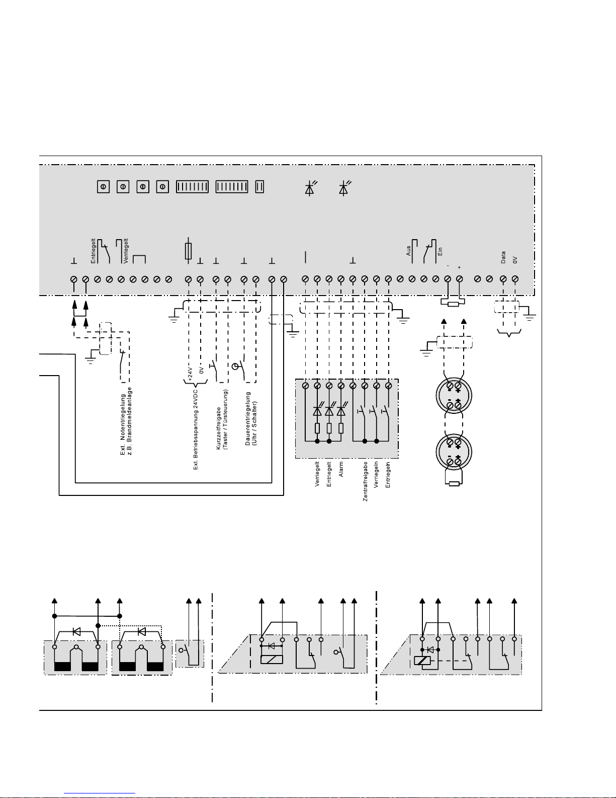
F4
1,25AT
+
-
S1 S2 S3 S6S4 S5 S7
(Schalterbelegung und Einstellung siehe Bedienungsanleitung)
16 17 18 19 20 21 22 23 24 25 26 27 28 29 30 31 32 33 34 35 36 37 38 39 40 41 42 43 44 45 46 47 48 A B
+UB
rt
gn ge
Zentralt ableau 725......
Relais - 5
max. 24V / 1A
Relais - 4
Alarmrelais
max. 24V / 1A
Melder-1
Melder-..n
2,43K
BM
BM
Brandmelderschleife
LED “NT”
grün
2,43 K
Fluchttürsteuergerät 720-30
ge
gn br
ws ge
gn br
ws
ABD EF
Türkontakt
Haftmagnet
Modell 827 24 V
Haftmagnet
Modell 827 24 V
Fluchttüröffner Modell 331 RR AKRR 24 V
AB DE F
Spule
Ankerkontakt
Rückmeldekontakt
rt
bl
gn
bl rt gn
bl rt
LED “AK”
gelb
74568321
Busanschluß
effeff TS-Bus
Pendeltüröffner Modell 351 RR AKRR 24 V
Ankerkontakt Türkontakt
(RR-Kontakt)
AB DEF
blgnrt
rt
bl
gn
rt
29
D0019203A0000700
Page 30

30
2.6 Anlagen mit indirekter (zentraler ) Freischaltung (Sonderfunktion I)
Ist i n e i n e r A n l a g e m i t mehreren Fl u c h t t ü r e n e i n e indirekte (zentr ale) Freischal tung aller Türen über eine
einzige Notschalterbetätigung gefordert, muß als Steuergerät Modell 720-32 eingesetzt werden. Dieses
Steuergerät ist mit einer Sicherheitsrelaisschaltung ausgestattet, über deren Kontakte das jeweilige
Verriegelungselement bestromt wird. Die zwangsgeführten Kontakte der drei Sicherheitsrelais, aus
denen die Schaltung aufgebaut ist, sind so mitei nander verknüpft, daß im Fehlerfall, wie beispielsweise
Kontaktverschweißen oder Feder bruch, das Wiedereinschalten der Verriegelung verhindert wird.
In diese m Fall wird die Stromversorgung der Sicherheitsrelais für alle Türen über eine Nottaste Modell
725 NAM-01 geführt und im Notfall zweipolig abgeschaltet.
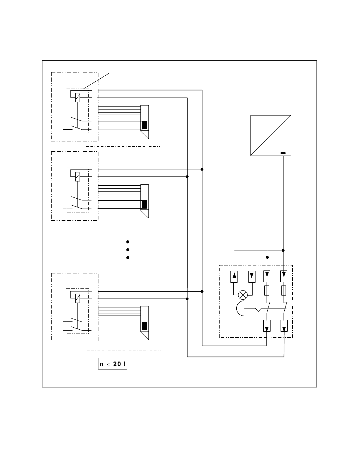
Es können maximal 20 Türen über ein Not- Abschaltmodul 725-NAM-01 geschaltet werden.
Gesamtstromaufnahme der Sicherheitsrelaisschaltung je Steuergerät 720-32: ca. 110 mA
Page 31
+
24 V DC
Tür 2
23
24
47
48
720-32
Steuergerät 2
+
–
23
24
47
48
720-32
Steuergerät 1
Sicherheitsrelaisschaltung
(Prinzipschaltbild)
+
–
Tür 1
Tür n
23
24
47
48
720-32
Steuergerät n
+
–
Not-AbschaltModul
725-NAM-01
Externes Netzteil
gemäß DIN EN 60950
Stromaufnahme der Sicherheitsrelaisschal tung: 110 mA
31
Abbildung 16: Anschlußschema indirekte Freischaltung D0019203A0000800
2.6.1 Anschlußschema indir ekte (zentrale) Freischalt ung
Page 32
1234567910 1113 14 16 17
rt
gn ge
Summer
Bedienteil 1332-10 / 11
1
2
34
5
6
7
8
9
10
111213
F 2
2 A T
F 3
1,25 A T
F 5
1,25 A T
F 6
1,25 A T
PO 1
Einstellbereich
Ausgangsspannung
24 V + 10%
AkkuLadespannung
PO 2
Achtung!
Wenn zwei Verriegelungselemente a
uf
das Steuergerät aufgeschaltet werde
n,
(z.B. bei zweiflügeligen Türen) müss
en
sowohl die Türkontakte, als auch die
Verriegelungsüberwachungen
(Ankerkontakt bzw. Hallelement)
in Reihe geschaltet werden.
F 1
0,5 A T
Netzspannung
230 V / 50-60 Hz
L1 N PE
L1 N PE
Haftmagnet Modell 828 24 V
Haftmagnet Modell 828 24 V
Türkontakt
Türkontakt
56432
56432
A
B
DE
F
C
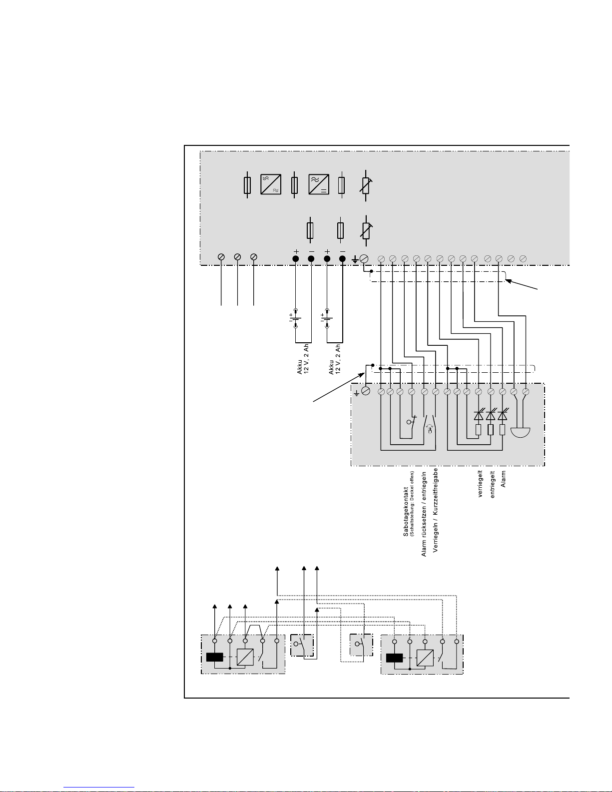
Ñ
Ò
32
Ñ Steuergerät und
Bedienteil müssen
über die Kabelschirme miteinander verbunden werden.
Diese d ü r fen jedoch
nur einseitig (am
Steuergerät) geerdet werden.
Ò Die Abschirmun-
gen aller am Steuergerät ankommenden Leitungen sind
dort auf die Erdungsschiene aufzulegen. Sie dürfen
nur einseitig geerdet
werden.
2.6.2 Gesamtanschlußplan 720-32
Page 33
+
-
24V-
230V~
Netz
230VAC / 5 0Hz
+
-
S1 S2 S3 S6S4 S5 S7
(Schalterbelegung und Eins tellung siehe Bedienu n gs a nleitung)
16 17 18 19 20 21 22 23 24 25 26 27 28 29 30 31 32 33 34 35 36 37 38 39 40 41 42 43 44 45 46 47 48 A B
+UB
F1
0,16AT
Sicherheits
-Relaisschaltung
720.22-92-02
ABCD
EF
Anschluß des
Verriegelungsteils
rt
gn ge
Zentraltableau 725......
Relais - 5
max. 24 V / 1A
Relais - 4
Alarmrelais
max. 24V / 1A
Melder-1
Melder-..n
2,43K
Brandmelder-
schleife
BM
BM
1514
F 7
0,1 A T
F 4
1,25 A T
LED “NT”
grün
LED “AK”
gelb
Fluchttürsteuergerät 720-32
ge
gn br
ws ge
gn br
ws
ABD EF
Türkontakt
Haftmagnet
Modell 827 24 V
Haftmagnet
Modell 827 24 V
Fluchttürö ffner Modell 331 RR AKRR 24 V
AB DE F
Spule
Ankerkontakt
Rückmeldekontakt
rt
bl
gn
bl rt gn
bl rt
2,43 K
7
4568321
Busanschluß
effeff TS-Bus
Pendeltüröffner Modell 351 RR AKRR 24 V
Ankerkontakt Türkontakt
(RR-Kontakt)
AB DEF
blgnrt
rt
bl
gn
rt
33
D0019203A0000900
Page 34
Kurzzeitfreigabezeit
Voralarmzeit
Alarmzeit
S 4
(nicht bestüc kt)
Funktionsvarianten
Busadresse
Voralarm
Stellung “ON” wen
n
Sicherheitsrelaisschaltun
g
nicht vorhanden
Akkuüberwachung
Dauerentriegelung
akustischer Alarm im T ür t er mi nal
Dauerfreigabe unverz öge rt
Kurzzeitfreigabe
Türüberwachung
nicht belegt
D0019202G0000400
34
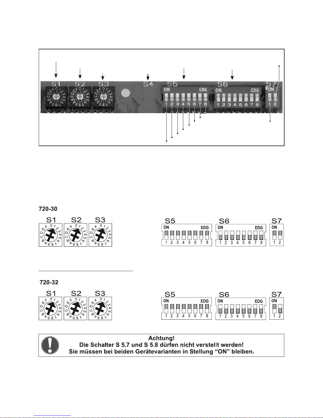
Abbildung 17: Einstellschalter D0019203G0000400
D0019203G0000500
2.7 Einstellschalter für Funktionen und Zeitabläufe
Mit den Einstellschaltern S 1 bis S 7 kann die Dauer der vom Fluchttürsteuergerät kontrollierten
Zeitabläufe und Varianten der Schalt- und Alarmierungsfunktionen vorgegeben werden.
2.7.1 Werkseitige Stellung der Einstellschalter
Page 35

35
2.7.2 Zeitvorgaben
S 1 Kurzzeitfreigabezeit
Mit dem Drehschalter S 1 wird die Dauer der
Türentriegelung bei Kurzzeitfreigabe festgelegt.
Wird die Tür innerhalb der hier vorgegebenen
Zeit nicht geöffnet, so wird sie wieder verri egelt.
Schließen der Tür bricht den Zeitablauf ab, so S 3 Alarmzeit
daß sie unverzüglich wieder verriegelt wird. Nach Ablauf der an S 3 eingestellten Zeit
Ist die Tür nach Ablauf der an S 1 vorgege- tet. Die Alarmsignalisierung durch die gelbe
bene Zeit noch geöffnet, werden Voralarm und LED und durch das Alarmrelais (Klemmen 42
danach Alarm ausgelöst, sofern die Funktion bis 44) bleibt jedoch bis zur Quittierung und
“Türüberwachung” nicht abgeschaltet wurde. Rückstellung des Alarms bestehen.
Schalterstellung 0: 11 Sekunden Schalterstellung 0: 11 Sekunden
Zeitraster: 11 Sekunden Zeitraster: 11 Sekunden
Schalterstellung F: 176 Sekunden Schalterstellung F: 176 Sekunden
S 2 Voralarmzeit S 4
Drehschalter S 2 gibt die Dauer des Vor- Schalter S 4 ist nicht bestückt.
alarms an. Wird die Tür nicht geschlossen, wird
nach A blauf dieser Zeit ein Vollal arm ausgelöst.
Schalterstellung 0: 4 Sekunden
Zeitraster: 4 Sekunden
Schalterstellung F: 64 Sekunden
wird die akustische Alarmmeldung abgeschal-
2.7.3 S 5 Funktionsvarianten
Mit den Schiebeschaltern des Schalterblocks S 5 können verschiedene Schalt- und Überwachungsfunktionen der Steuerung ein- oder ausgeschal tet werden.
S 5.1 Türüberwachung
Schalterstellung “on”: Die Tür wird auf eine
maximal zulässige Öffnungszeit überwacht.
(Siehe auch: “Kurzzeitfreigabezeit” und “Voralarmzeit”!)
Schalterstellung “off”: Die Öffnungsdauer der
Tür nach Kurzzeitfreigabe oder nach Ablauf einer Dauerentriegelung bei offener Tür wird nicht S 5.3 Unverzögerte Dauerentriege-
überwacht. Eine offen gebliebene Tür löst also
keinen Alarm aus.
S 5.2 Kurzzeitfreigabe traltableau)
Schalter S 5.2 beeinflußt lediglich die Funktion des Steuereingangs Klemme 4 (Schlüssel- Bei Schalterstellung “on” wird ein Dauerentdrehung nach rechts am Türterminal bzw riegelungsbefehl unverzögert angenommen.
Terminal-Modul).
Bei Schalterstellung “on” und verriegelter Tür triegelungsbefehl nur angenommen, wenn das
bewirkt ein Tastimpuls auf diesen Eingang die Signal länger als 5 Sekunden ansteht.
Auslösung einer Kurzz eitfreigabe. (Siehe oben!)
In Schalterstellung “off” kann an Klemme 4
ausschließlich der Steuerbefehl “verriegeln” gegeben werden.
Die Kurzzeitfreigabe über die Klemmen 27
und 28 wird durch die Stellung von S 5.2 nicht
beeinflusst.
lung
Schalter S 5.3 beeinflußt die Funktion des
Steuereingangs Klemme 3 (Schlüsseldrehung
nach links am Terminal) und Klemme 40 (Zen-
Bei Schalterstellung “off” wird ein Daueren-
Page 36

36
Die Funktion des Steuereingangs “Daueren- Bei Schalterstellung “on” ist eine Dauerentriegetriegelung” an Klemmen 29 und 30 wird durch lung über den Schlüsselschalter im T erminal
die Stellung von S 5.3 nicht beei nflußt. möglich.
S 5.4 Akustischer Alarm
Über diesen Schalter kann das akustische
Alarmsignal im Türterminal oder Terminal-Modul bei zentraler Alarmauslösung ausgeschaltet
werden.
In Schalterstellung “on” wird jeder Alarm Mit Schiebeschalter S 5.6 muß, in den Fällen
auch akustisch im Terminal signalisiert. wo keine Akkus angeschlossen sind, deren
In Schalterstellung “off” werden die Alarmursa- Schalter in Stellung off gebracht wird.
chen:
-Ext. Notentriegelung Bei externer Spannungsversorgung muß
-Zentral-Not-Auf (720-32) Sc halter S 5.6 in Stellung off stehen! – Akkus
-Zentralfreigabe Klemme 38 dürfen dann nicht angeschlossen werden! Das
am Terminal nicht akustisch signalisiert. Netzteil muß DI N EN 60950 entsprechen.
S 5.5 Dauerentriegelung
Schalter S 5.5 beeinflußt lediglich die Funk- S 5.7, S 5.8
tion des Steuereingangs Klemme 3 S 5.7 und S 5.8 sind für Kundenspezifische
Bei Schalterstellung “off” kann vom Terminal
aus keine Dauerentriegelung ausgelöst werden.
Der Steuereingang “Dauerentriegelung”
(Klemmen 29-30) wird durch die Stellung von S
5.5 nicht beeinflußt.
S 5.6 Akku-Überwachung
Überwachung abgeschaltet werden, indem der
Speziallösungen reserviert. Bei den Standard-
Versionen der Steuergeräte 720-30 und 72032 müssen beide Schalter in Stellung “ON”
stehen.
2.7.4 S 6 Busadresse
Der Schalterblock S 6 wird nur benötigt, wenn das Steuergerät mit einem zentralen Steuerungstableau 925 verbunden ist und von di esem gest euert und überw acht w ird. Ist dies der Fall, wird an diese
Schaltern der Busbetrieb akti v ier t und di e Geräteadresse eingest ellt. Näheres dazu findet sich auf Seite
35 und in der Anleitung zum Steuerungstableau 925.
Wird das Fluchttürsteuergerät als Einz el gerät betr ieben, oder ist es nur mit einem Zentraltableau 725
verbunden, müssen alle Schalter von S 6 in Stellung “off” stehen.
2.7.5 S 7 Sonderfunktionen
S 7.1 Voralarm S 7.2 Sicherheitsrelaisschal tung
Wenn bei einer Kurzzeitfreigabe, nach Ab- Schalter S 7.2 muß beim Fluchttürsteuergelauf der an S 1 vorgegebenen Zeitdauer, die Tür rät 720-32 oder bei Nachrüstung eines Geräts
noch offen steht, beginnt die Voralarmzeit (S 2) 720-30 mit der Relaissteckkarte für zentrale
abzulaufen. In Schalterstellung “ON” wird dies Freischaltung in Stellung “off” stehen.
akustisch mit verminderter Lautstärke signalisiert.
In Schalterstellung “OFF” erfolgt diese akustische Warnung vor einer bevorstehenden
Alarmauslösung nicht. (Die Voralarmzeit läuft
dennoch ab.)
Page 37

37
2.8 Steuereingänge
Externe Notentriegelung (Kl 16-17)
Auf diesen Eingang kann beispielsweise der
Meldekontakt einer ext ernen Brandmeldeanlage
als Öffner aufgeschaltet werden.
Wenn keine externe Notentriegelung vorgesehen ist, muß hier eine Brücke eingesetzt werden. Dauerentriegelung (Kl 29-30)
Das Öffnen dieses Eingangs schaltet das lung ssystem durch einen ex ternen Kontakt dauFluchttürsteuergerät unverzüglich auf Alarm; die ernd entriegelt werden. Dieser kann beispielsTür wird entriegelt. Quittieren des Alarms am weise der Ausgangskontakt einer Schaltuhr
Fluchttürterminal (Schlüsseltaster nach links) sein, wenn die Dauerentriegelung regelmäßig
schaltet die akustische Signalisi erung ab. zu bestimmten Zeiten akt iviert werden soll.
Mit dem Schließen des Eingangs wird der Die Dauerentriegelung wird aktiviert, wenn
Alarm zurückgesetzt; di e Tür wird wieder verr ie- der Kontakt schließt. Öffnet der Kontakt wieder,
gelt, sofern sie geschlossen ist. wird die Tür unverzüglich wieder verr iegelt.
Ist die Tür geöffnet worden, wi rd die Türüber- Öff net der Kontakt bei offener Tür, wird der
wachung gestartet. Nach Ablauf der Überwa- Funktionsablauf “Türüberwachung” gestartet:
chungszeit und gegebenenfalls des Voralarms, Die grüne LED am Türterminal oder Terminalerfolgt Alarmauslösung. Modul beginnt zu blinken; nach Ablauf der Tür-
Kurzzeitfreigabe (Kl 27-28)
Über diesen Eingang kann durch einen externen Taster eine Kurzzeitfreigabe mit automatischen Zeitabläufen, analog den Abläufen bei
Kurzzeitfreigabe vom Tterminal aus, ausgelöst
werden.
Er wird beispielsweise benutzt, um die
Fluchttür durch ein Zutrittskontrollsystem oder
einen Türöffnertaster freizugeben. Der Eingang
ist nachtriggernd.
Über die Klemmen 29-30 kann das Verriege-
überwachungszeit wird – sofern aktiviert – Voralarm ausgelöst; und nach dessen Ablauf wird,
falls die Tü r weiterhin offen ist, Alarm ausgelöst.
2.9 Meldeausgänge
Das Fluchttürsteuergerät 720-30 / 32 st ellt zwei Relaisausgänge zur Verfügung, die als potentialfrei e
Umschaltkontakte auf die Klemmen 18 bis 20 und 42 bis 44 geführt sind. Über sie können die Zustände
“Verriegelt”, “Entriegelt” und “Alarm” weitergemeldet werden .
Die Relaiskontakte sind mit maximal 1 A und maximal 24 V belastbar.
Page 38

38
2.10 Anschluß von Brandmeldern (Klemmen 45-46)
Das effeff-Fluchttürsteuergerät 720-30 / 32 enthält eine Auswerteeinheit zum direkten Anschluß von
Brandmeldern. Sind Brandmelder angeschlossen, wird bei Auslösen eines Melders der Linie unverzüglich die Tür entriegelt und Alarm ausgelöst.
Verwendbare Brandmelder
An das Fluchttürsteuergerät können bis zu 5 Anschluß der Brandmelder
effeff-Brandmelder der Typenreihen 60 030 (op- Alle anzuschließenden Melder werden in eitischer Rauchmelder) angeschlossen werden. ne Schleife eingeschleift. Als AbschlußwiderDer optische Rauchmelder 60030 detektiert stand muß ein Widerstand von 2,43 k
S über die
Rauch nach dem Streulichtprinzip. Er wird be- Ausgangsklemmen des letzten Melders gevorzugt dort eingesetzt, wo in der Entstehungs- schaltet werden.
phase mit einem Schwelbrand z u rechnen ist.
Anordnung der Brandmel der Betrieb ohne Brandmelder
Bei der Anordnung der Brandmelder wird Wenn das Fluchttürsteuergerät ohne direkt
davon ausgegangen, daß ein einzelner Melder angeschlossene Brandmelder betrieben wird,
einen Bereich überwacht mit einem waagrech- muß der Abschlußwiderstand mit 2,43 k
S direkt
ten Abstand von ca. 2 Meter um die Position über die Anschlußklemmen 45-46 verdrahtet
des Melders. werden (=Auslieferungszustand).
Page 39
oder
720-30
720-32
S 1
S 2 S 3
S 4
L 1
Elektrosich erheitsschloß 809
Ausbauversionen mit vier Überwachungskontakten
Arbeitsstromausführung für 24 V DC
18
19
25
26
27
28
Freigabetaster
z.B. von
Zutrittskontrollsystem
42
43
L 1 = Spule:
Polarität und Nennspannung beachten!
S 1 = Riegelschaltkontakt
(gezeichnet = Riegel ausgeschlossen).
S 2 = Endschalter Tür-Außendrücker
schaltet nur bei Betätigung des Tür-Außendrückers.
S 3 = Endschalter Tür-Innendrücker
schaltet bei Betätigung des Tür-Innendrückers.
S 4 = Profilzylinderkontakt
schaltet nur bei Betätigung des Profilzylinders.
Der die Spule ansteuernde Kontakt
ist bei der Arbeitsstromversion als
Arbeitskontakt ( Schließer), bei der
Ruhestromversion als Ruhekontakt
( Öffner ) aufzuschalten.
Hinweis:
sämtliche Kontaktstellungen sind unbetätigt
gezeichnet.
Bei Betätigung des aufgekoppelten Außendrückers
werden beide Türdrückerkontakte geschaltet.
Riegelschaltkontakt
Außendrückerkontakt
Innendrückerkontakt
Profilzylinderkontakt
39
D0019203A0001000
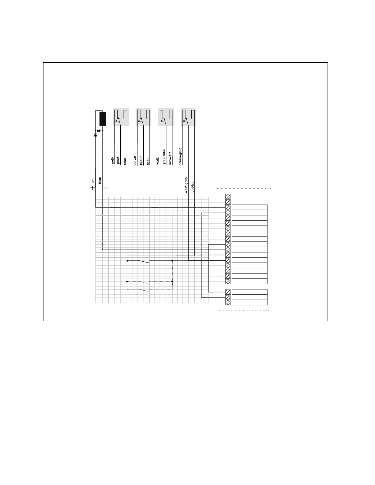
2.11 Sonderfunktion II: Betrieb des Fluchttürsteuergeräts mit dem Elektrosi-
cherheitsschloß 809
Werden an einer Tür sowohl eine Fluchttürsicherung mit dem Steuergerät 720-30 oder 720-32 als auch
ein Elektrosicherheitsschloß 809 eingesetzt, empfiehlt es sich, die Verschaltung entsprechend obigem
Anschlußplan auszuführen.
Das Elektrosicherheitsschloß wird über den Gefahrentriegelung der Fluchttürsicherung das
Relaisausgang “entriegelt” des Fluchttürsteuer- Elektrosicherheitsschloß nicht angesteuert wird.
geräts angesteuert.
Im oben wiedergegebenen Anschlußschalt- heitsschlosses steuert seinerseits den Eingang
bild ist zusätzlich der Öffner des Alarmrelais in Kurzzeitfreigabe des Fluchttürsteuergeräts an.
die Ansteuerleitung geschleift, so daß bei einer
Der Profilzylinderkontakt des Elektrosicher-
Page 40
ON
¼
20 = 1
¼
21 = 2
¼
22 = 4
¼
23 = 8
¼
24 = 16
¼
25 = 32
¼
26 = 64
Busbetrieb Ein / Aus
ON
¼
20 = 1
¼
21 = 2
¼
23 = 8
¼
24 = 16
¼
25 = 32
Busbetr ieb Ein
Beispiel:
Adress-Nr. = 59
3
= 59
40
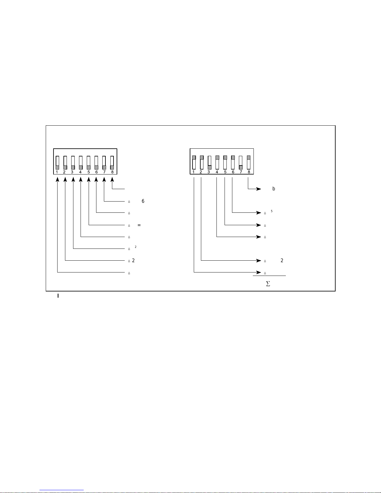
Abbildung 20: Einstellung der Teilnehmeradresse für den Busbetrieb D0019203G0000600
2.12 Sonderfunktion III Betrieb der Steuerung am Steuerungstableau 925 (Bus-
Technologie)
Wenn das Fluchttürsteuergerät 720-30 oder 720-32 an ein zent ra les Steuer- und Überwachungstableau
(Bus-Steuerungstableau) 925 angeschlossen ist, sind die Schalt- und Anzeigefunktionen an der Tür
bzw. am Terminal im wesentlichen die gleichen.
Einstellung der Bus-Adresse ( S 6 )
Bei Betrieb am Bus-Steuerungstableau 925 muß jedem Steuergerät eine eigene Teilnehmeradresse
zugewiesen werden, die sowohl am DIP-Schalter S 6 des Steuergeräts selbst, als auch an der zugehörigen Türeinheit des Zentraltabl eaus eingestellt werden muß.
Anschluß des Türsteuerbusses
Die zweiadrige Busleitung des Türsteuerbusses wird auf die Klemmen A und B des Fluchttürsteuergeräts aufgelegt. Achtung! Leitungen A und B nicht verwechseln!
Entnehmen Sie bitte alle weiteren Informationen zu Installation, Funktion und Inbetriebname der
”Bedienungs- und Installationsanleitung zum Bus-Steuerungstableau Modell 925”!
Page 41

41
2.13 Technische Daten
Spannungsversorgung 230 V +6%, -10%, 50 - 60 Hz
Maximale Stromaufnahme bei Nennspannung 0,3 A
Eingangsspannungsbereich bei ext. Stromversorgung 24 V DC stabilisiert +15%, -10%
(Sicherheitskleinspannung)
Eigen-Stromaufnahme der Steuerung 150 mA
Stromaufnahme der Sicherheitsrelaisschaltung in 720-32 110 mA
Betriebsnennspannung 24 V DC
Maximal zulässige Gesamtstromaufnahme aller exter nen Verbraucher ca 1,1 A
Notstromversorgung / Akkukapazität 24 V DC, 2Ah
Überbrückungszeit bei Nennlast: ca. 15 Minuten
Schutzmaßnahme nach VDE 0100: Schutzklasse I
Schutzart nach DIN 40050 IP 20
Betriebstemperaturberei ch 0°C bis +40°C
Lagertemperaturbereich -20°C bis +60°C
Abmessungen BxHxT in mm 300 x 186 x 125
Farbe RAL 9002 Grauweis
Gewicht (ohne Akkus)
720-30: 5,28 kg
720-32: 5,52 kg
Gewicht Akkus (2 Stück 18002) 1,92 kg
Page 42

42
3 Inbetriebnahme, Wartung, wiederkehrende Prüfung
Einbau und Betrieb von elektrischen Verriegelungen von Türen in Rettungswegen unterliegen bauaufsichtlichen Regelungen, deren Einhaltung sowohl von Seiten des Installateurs als auch seitens des
Betreibers sicherzustellen ist.
3.1 Inbetriebnahme und w i ederkehrende Prüfung
Vor der ersten Inbetriebnahme eines elektrischen Fluchttürverriegelungssystems muß der ordnungsgemäße
Einbau aller Elemente und deren elektrischer Anschluß überprüft werden. Besondere Sorgf alt ist hierbei auf die
Elemente zur Freischaltung der Verriegelung im Gefahrenfall zu verwenden.
In der Regel ist der ordnungs gemäße Einbau und die Funktionsf ähigkeit der elektrisc hen Fluchttürverriegelung
durch einen Sachkundigen festzustellen.
Darüber hinaus müssen Türen in Rettungswegen mit elektrischen Verriegelungen mindestens einmal jährlich von
einem Sachkundigen geprüft werden. Der Sachkundige hat über die wiederkehrende Prüfung eine Bescheinigung
auszustellen, die der Betreiber der Bauaufsichtsbehörde auf Verlangen vorzulegen hat.”
Achtung!
Bei de n vo r stehenden Hi nweisen handel t e s sich um Standardvorgaben. Da der Einsatz von Rettungswegverriegelungen auf Ebene der Bundesländer geregelt ist, sind in jedem Fall die betreffende Landesbauordnung und die Prüfverordnungen für technische Anlagen zu beachten.
3.2 Wartung
Die Ge räte bedürf en keiner W artung. Treten während des Betriebs oder bei einer der vorgesc hr iebenen Prüf ungen Störungen auf, die nicht durch fehlerhafte Installation oder Montage verursacht wurden, so ist das betreffende
Gerät unverzüglich außer Betrieb zu nehmen und zur Überprüfung an den Hersteller zu senden.
Die Wartungsfreiheit der Geräte entbindet nicht von der Pflicht zu regelmäßig wiederkehrender Prüfung der
Fluchttürverriegelung!
Page 43

43
D0019203G0000700
4 Checkliste zur Prüfung vor Erstinbetriebnahme
Komponenten
C Alle Komponenten entsprechen der EltVTR
– eingebautes Verriegelungselement ....................................................................................................
– Steuerung ..........................................................................................................................................
– Bedienelement ..................................................................................................................................
C
Einbau- und Betriebsanleitung ist vorhanden ........................................................................................
C
Formular für Prüfung des Fluchttürverriegelungssystems vor Erstinbetriebnahme ist vorhanden ........
Bei externer Stromversorgung des Verriegelungssystems oder von Teilen desselben:
C Entspricht die Energieversorgung EN 60 950 (CE-Zeichen vorhanden)? ............................................
Einbau
C Die lichte Durchgangshöhe der Tür wird durch das Verriegelungselement nicht auf einen Wert unter 200
cm eingeschränkt. .................................................................................................................................
C
Die Positionierung des Nottasters entspricht den Vorgaben des Landesbaurechts und den Richtlinien über
elektrische Verriegelungen von Türen in Rettungswegen. ...................................................................
C
Das Hinweilschild “NOTTASTE” ist vorhanden und korrekt angebracht. .............................................
Bei Einbau der Verriegelung an einer Rauch-/ Feuerschutztür:
C Positionierung und Einbauweise des Verriegelungselements entsprechen den Vorgaben des Eignungs-
nachweises des Türherstellers ..............................................................................................................
Funktion
- Verriegelungssystem aktivieren!
- Prüfen, ob rote Anzeige am Bedienelement leuchtet!.
- Prüfen (manuell), ob Tür sicher verriegelt ist!
- Nottaste im Terminal bzw. im Tableau (bei indirekter Freischaltung) betätigen!
C Die Tür wird unverzögert freigegeben. ..................................................................................................
C
Die Tür kann ohne erheblichen Kraftaufwand geöffnet werden ............................................................
C
Gelbe und grüne LED am Terminal leuchten. .......................................................................................
C
Der integrierte akustische Alarmgeber hat angesprochen. ...................................................................
-
Alarm zurücksetzen!
- Verriegelungssystem aktivieren!
- Prüfen, ob rote Anzeige am Bedienelement leuchtet!.
- Prüfen (manuell), ob Tür sicher verriegelt ist!
- System auf Dauerentriegelung schalten!
C Tür ist entriegelt. ...................................................................................................................................
-
Nottaste im Terminal bzw. im Tableau (bei indirekter Freischaltung) betätigen!
C Gelbe und grüne LED am Terminal leuchten. ......................................................................................
C
Der integrierte akustische Alarmgeber hat angesprochen. ..................................................................
Wenn eine Gefahrenmeldeanlage (z.B. Brandmeldeanlage) aufgeschaltet ist:
- Alarm zurücksetzen!
-Verriegelungssystem aktivieren!
- Prüfen, ob rote Anzeige am Bedienelement leuchtet!.
- Prüfen (manuell), ob Tür sicher verriegelt ist!
- Ruhestromschleife der Gefahrenmeldeanlage öffnen!
C Die Tür wird unverzögert freigegeben. ...................................................................................................
C
Die Tür kann ohne erheblichen Kraftaufwand geöffnet werden .............................................................
C
Gelbe und grüne LED am Terminal leuchten. .......................................................................................
C
Der integrierte akustische Alarmgeber hat angesprochen. ...................................................................
Page 44

eff-eff Fritz Fuss GmbH & Co
Kommanditgesellschaft auf Aktien
Bildstockstraße 20
72458 Albstadt-Ebingen
Deutschland
Tel.: (07431) 123-0 http/www.effeff.com
fax (07431) 123-240/303 [email protected]
An ASSA ABLOY Group company
ASSA ABLOY
Page 45
Security and precision
Emergency Exit Control Unit 720-30
720-32
Operating and
Installation Instructions
D0019203
(OW 975
7h95KHLQODQG
Page 46

46
Contents
1 Operation and functional characteristics ...........................................................................................47
1.1 Door terminal and terminal module 48
1.2 Overview of operating displays 49
1.3 Monitoring and alarm functions 50
1.3.1 Actuating the emergency button 50
1.3.2 Door open monitoring 50
1.3.3 Locked status monitoring function 50
1.3.4 Door sabotage 50
1.3.5 Sabotage at the door terminal, terminal module or control unit 50
1.3.6 Sabotage to cables 50
1.4 Switching functions 51
1.4.1 Temporary release 51
Permanent unlocking 51
1.4.3 Locking 51
1.4.4 Alarm reset 51
1.5 Function variants 53
1.5.1 Temporary release 53
1.5.2 Permanent unlocking 53
1.5.3 Pre-alarm 53
1.5.4 Alarm 53
1.5.5 Alarm time 53
1.6 Special function I: Systems with indirect release. The Emergency Exit Control Unit 720-3254
1.7 Special functions II: Operation of the emergency exit control unit using electrical security lock 809 55
1.8 Special function III: Operation at the effeff door control bus with control panel 925 56
1.9 Determination of an alarm condition57
1.10 Eliminating the reasons for the alarm 58
2 Installation ............................................................................................................................................. 59
2.1 Mounting the control unit 60
2.2 General information on the electrical installation 61
2.3 Cable diagrams and connection details 62
2.3.1 Emergency exit security system for a single-leaf door (cable diagram) 62
2.3.2 Emergency exit security system for a two-leaf emergency exit (cable diagram) 63
2.3.3 Mains and battery connection 64
2.4 Locking systems with the door terminal 1337-10/11 66
2.4.1 Connection detail parallel connection control unit 1332 and door terminal 1337-10/11 66
2.4.2 Connection detail: Parallel connection of two door terminals 1337-10/1167
2.4.3 Overall terminal diagram 720-30 with door terminal 1337-10/1168
2.5 Locking systems with terminal module 1370-10 70
2.5.1 Connection detail: Terminal module 1370-10 with operator terminal 1332 70
2.5.2 Connection detail parallel connection of two terminal modules 1370-10 71
2.5.3 Overall terminal diagram 720-30 with terminal module 1370-1072
2.6 Systems with indirect (central) release (special function I) 74
2.6.1 Terminal diagram, indirect (central) release 75
2.6.2 Overall terminal diagram 720-32 76
2.7 Setting switches for functions and time sequences 78
2.7.1 Default positions of setting switches78
2.7.2 Time inputs 79
2.7.3 S 5 function variants 79
2.7.4 S 6 Bus address 80
2.7.5 S 7 Special functions 80
2.8 Control inputs 81
2.9 Signal outputs 81
2.10 Connection of fire alarm systems (terminals 45-46) 82
2.11 Special function II: Operation of the emergency exit control unit with the electrical security lock 80983
2.12 Special function III Operation of the control system at control panel 925 (bus technology) 84
2.13 Specifications 85
3 Commissioning, maintenance, recurring tests.................................................................................. 86
3.1 Commissioning and recurring tests 86
3.2 Maintenance 86
4 Checklist for testing prior to initial commissioning.......................................................................... 87
Page 47

47
1 Operation and functional characteristics
Doors positioned in escape routes - Em ergenc y exits - m ust be capable of being opened at any time without
outside aids. As a result, their locks must feature a panic function, i.e. when actuating the internal handle , the prelocked bolt must als o open. On the other hand, the doors must remain locked for security reasons. This leads in
many instances in administrative buildings, department stores, industrial plants and similar properties to problems.
The relevant doors can no longer be effectively monitored.
In order to gain control over this situation without incurring unreasonable expense, systems are integrated which
electrically lock the doors, monitor their locked status and signal when they are opened or unlocked.
To allow opening in case of emergency this type of system - with only a few exceptions - is always equipped w ith
an emergency switch whose actuation imm ediately switches off the electrical lock, and so r eleases the door for
people to pass through and initiates an alarm.
The locking elements must hold the door shut with suff icient holding power and reliably unlock it in case of
emergency, even when it is subjected to a preload.
Furthermore, this type of system must also offer certain control functions to allow doors to be briefly or
continuously released should the circumstances so require.
In addition, it must also be possible for a fire alarm system, if available, to trigger emergenc y unlocking of the
door.
As a supplementary function, the effef f em ergency exit control unit 720-30/32 f eatures an evaluating unit for
effeff smoke detectors.
Generally, the emergency exit terminal 1337-10/11 or the terminal module 1370-10 is used as a control and
signalling device for the effeff emergency exit control unit. On a parallel basis, a 1332 control unit - for example as
an external operator terminal -and also a central control panel can be connected to the emergency exit control unit.
In exceptional cases, i.e. when release of the door(s) should take place only from a central location, the 1332
control unit can also be used directly at the door as a stand-alone switching and display element. However, then
special regulations must be observed and model 720-32 equipped with a special security relay circuit must be used
as a control unit.
Note!
The relevant statutory building regulations must be observed when installing and operating electrical
locks in escape routes.
Agreement of the units with the "Directive on locking systems for doors in escape route s (EltV TR 12/97)”
(Building register A part 1, no. 6.19) has been tested by TÜV Rheinland in Cologne.
Test Certificate no: R 2011393
Page 48
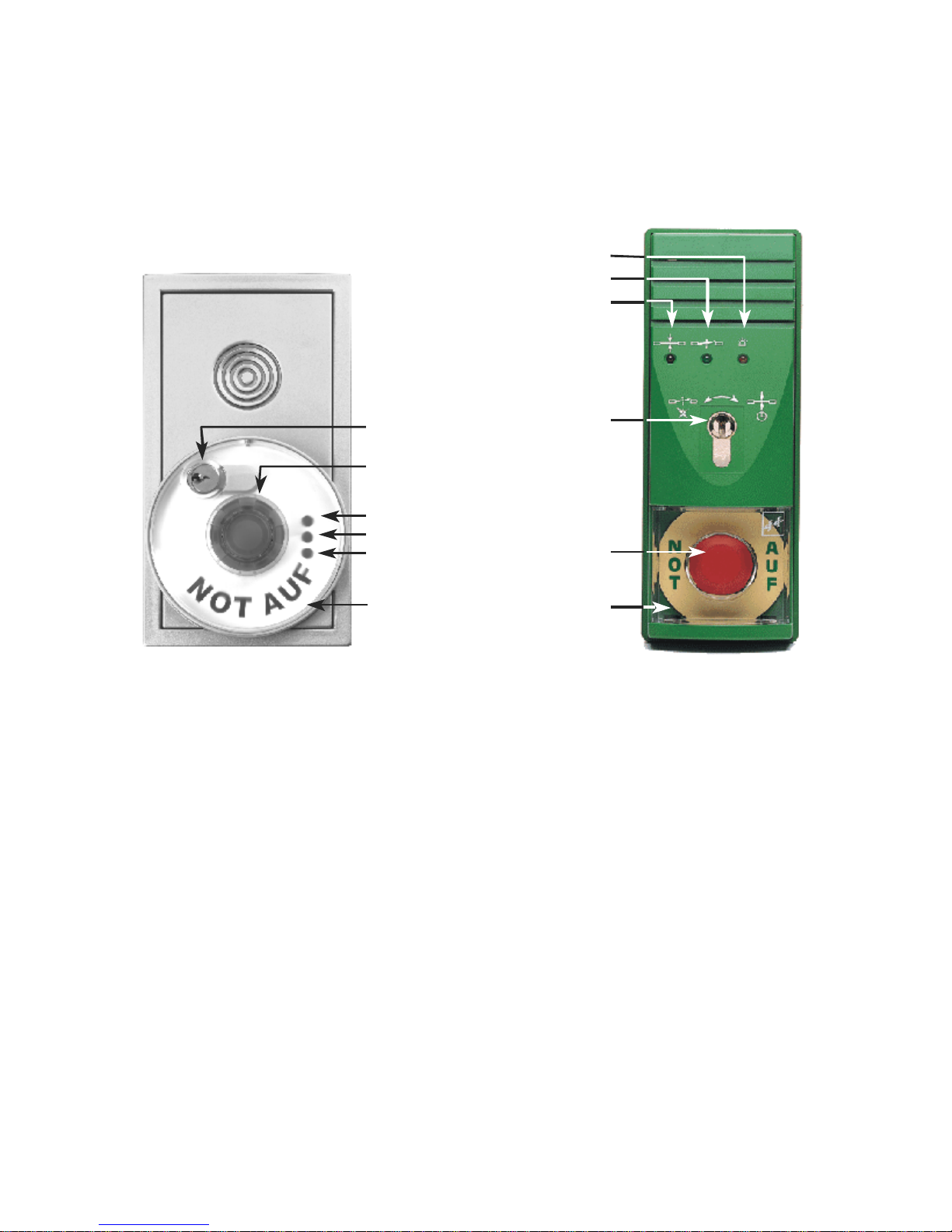
48
1.1 Door terminal and terminal module
Generally, a 1337-10/11 do or terminal or the terminal module 1370-1 0 (Fig. 2) is used as a n e mergency exit security
switching or display device (exceptions see page 9: "Special function I …"). This f eatures three LEDs for optical
display of the operating status, a key-operated switch for all operational s witching f unc tions , the red panic button
for door release and, integrated in the housing, an alarm buzzer.
The most important element of the door terminal and
the terminal module in acc ordance with Fig. 2 is the
emergency switch, which is designed as a red
illuminated panic button. This interrupts the circuit of
the locking element when actuated and so unlocks it.
At the same time, an alarm is triggered. The actuating
button locks into place and has to be pulled out again
before the alarm can be reset.
In the case of the door terminal 1337-10/11, the cover
cowl over the panic button is pressed in at the same
time, but not damaged. It can be pulled out without the
need to use any instrument and used again after the
panic button has been pulled back out.
In the door terminal 1337-10, the red cap of the
panic button only is pressed in case of emergency. To
reset the emergency switch, the transparent cover
cowl must first be unlocked with the aid of the key (for
more details, see page 8).
The key-operated switch integrated in the door
terminal or terminal module can be used to switch all
operating functions of the emergency exit security
system such as temporary and continuous unlocking,
locking and alarm acknowledgement.
Three LEDs indicate the current status of the
locking system:
The yellow LED indicates a live alarm
The green LED indicates an unlocked door
The red LED indicates a locked door.
Ñ
Ò
Ó
Ô
Õ
Ö
1337-101370-10
Ñ
Ò
Ó
Ô
Õ
Ö
Page 49
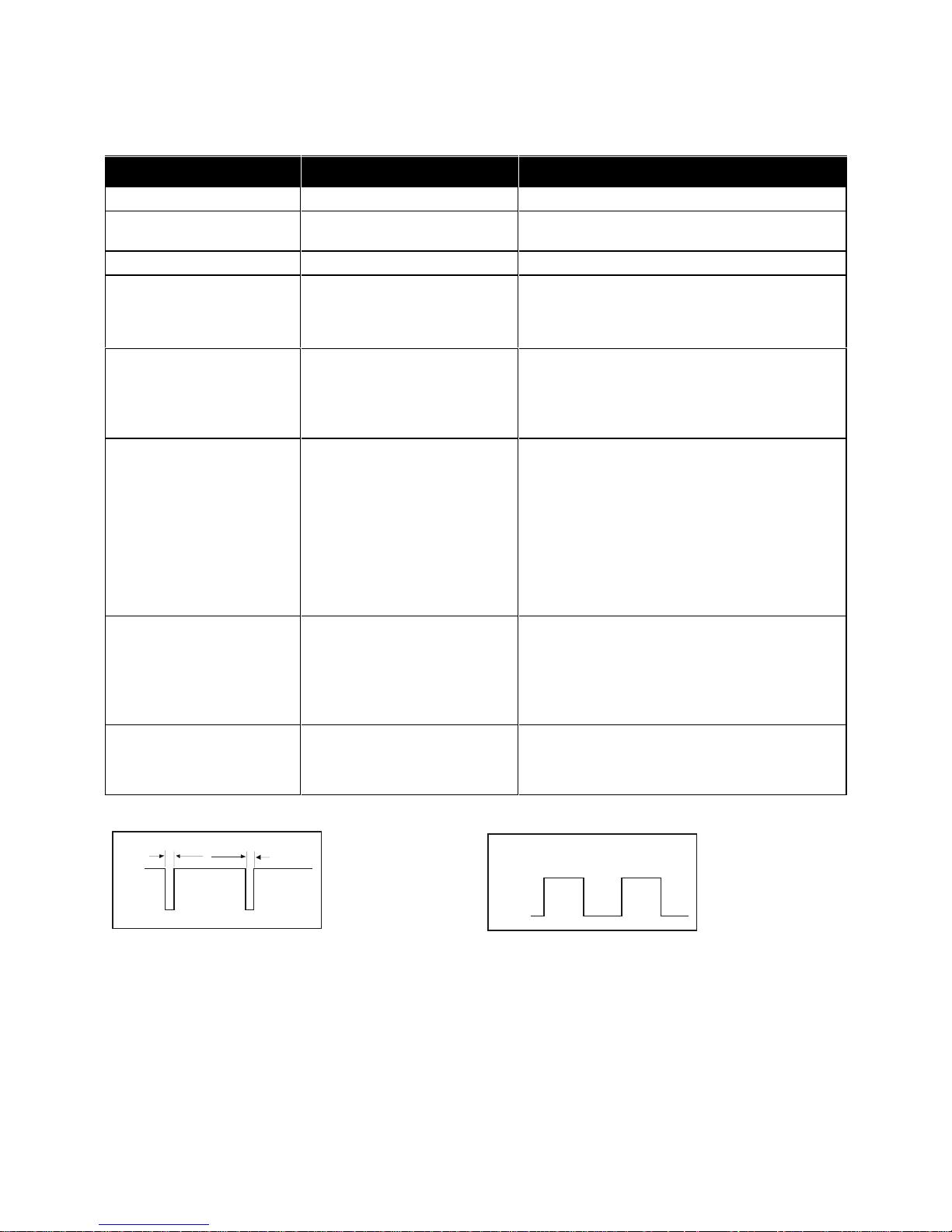
49
1.2 Overview of operating displays
LEDs which light up Operating status Remarks
RED
Locking active
GREEN
Continuous release
The door can be locked by turning the key to
the right. If this is not possible, it is not closed.
YELLOW
Alarm
GREEN FLASHING
with short breaks
Duration of a temporary
release
The time sequence is automatically interrupted
by opening and closing the door.
It can be manually interrupted by turning the key
to the right.
GREEN FLASHING
with break and lighting
times of equal length
An alarm has been initiated.
Although this has been
acknowledged, the cause of
the alarm is still active.
The cause of the alarm can be ascertained with
the aid of the table on page 8. After eliminating
the cause of the alarm (the green LED then
lights up continuously) the door can be locked
again by turning the key to the right.
GREEN and YELLOW
Danger alarm
Possible alarm causes:
• The emergency switch has been
actuated.
• A smoke detector has triggered.
• The fire alarm control centre has been
triggered.
• A locking command could not be
executed.
This display also appears if the terminal housing
is opened when the door is unlocked.
RED and YELLOW
Sabotage alarm
The door remains locked.
Possible alarm causes:
• The housing of the door terminal /
terminal module has been opened.
• The door contact has been opened
(sabotage at the door).
YELLOW FLASHING
Red and green according
to switching status.
Battery operation
(power failure)
When the power is returned, this alarm resets
automatically.
The device retains its switching status.
Bridging time at least 15 mins.
(*) The puls e- paus e ra t io
is appr. 9:1. This means
that the light phase is
nine times longer than the
dark phase.
(**) The pulse-pause
ratio is appr.1:1. This
means that the light
phase and the dark
phase are approximately
the same length.
ON
OFF
1
9
1
ON
OFF
Page 50

50
1.3 Monitoring and alarm functions
Each alarm of the emergency exit security system
must be reset via the key-operated switch in the door
terminal or terminal module, after remedying the
cause of the alarm.
If the key-operated switch is actuated after an
alarm has been triggered without first eliminating the
cause of the alarm, this is only acknowledged. The
external indication and acoustic signal in the door
terminal or the terminal module are switched off, the
yellow LED goes out, the green LED switches over to
a flashing signal. It is not possible to re-lock the door.
1.3.1 Actuating the emergency button
Pressing the emergency button results in an
immediate release of the door and always initiates an
alarm. The acoustic alarm signal is switched off by
turning the key-operated switch to the left
(acknowledging the alarm).
In order to lock the door again, initially the
depressed emergency button has to be pulled out.
Turning the key to the right then locks the door again.
1.3.2 Door open monitoring
When opening a door which has been switched
over to temporary release, a monitoring f unction is
activated for the remaining period of the set
temporary release time. If the door is not closed
within this "Door monitoring time", initially a warning
is issued in the form of in intermittent acoustic alarm
with diminishing volume, and after expiry of the prealarm period an alarm is given off.
If the door is closed within the pre-alarm period, it
locks. No alarm is initiated.
If the door is only closed after an alarm is
triggered, the external alarm signal and the acoustic
alarm signal in the door terminal or term inal m odule
are switched off. The door is locked, and the optic al
display continues to indicate an active alarm.
Acknowledgement of the alarm and manual reset at
the key-operated switch of the door terminal or
terminal module are then required.
Identical sequences result when the door remains
open when switching off a continuous unlocked
status.
1.3.3 Locked status monitoring function
If the used locking elements are fitted with the
relevant monitoring contacts, maintenance of the
"locked" status and successful execution of the
"locking" command when the door is closed are
monitored.
In the case of emergency exit release 331 RR
AKRR, this function is monitored by the armature
contact, in the case of sur face holding magnet 828,
an integrated Hall-effect element signals completion
of the locking magnetic field.
If, when using model 828, the door is opened by
violence, or if a locking command cannot be
implemented when the door is closed bec ause, for
example, the counter-holding plate is not making
contact with the magnet, an alarm is triggered.
1.3.4 Door sabotage
If a locked emer gency exit is sabotaged so that
this can be detected by the monitoring contact
integrated in the door contact / the emergency exit
release, an alarm is triggered immediately. Following
this type of sabotage alarm the door will not unlock.
1.3.5 Sabotage at the door terminal, terminal
module or control unit
The control and display units are protected by a lid
contact. In the event of an attempted sabotage by
opening the device, an alarm is also immediately
triggered. Also in the case of this type of sabotage
alarm, the door is not unlocked.
1.3.6 Sabotage to cables
The cables between the emergency exit c ontrol
unit and the locking element are also m onitor ed. An
interruption to a cable results in an immediate alarm
being triggered.
Page 51

51
1.4 Switching functions
The key-operated switch of the door terminal or
terminal module has two momentary contact
functions which - depending on the output status initiate differing switching processes.
1.4.1 Temporary release
From the "locked status", turning
momentarily to the right initiates a
temporary release. This means that the
current to the locking element is interrupted for a
certain time and after expiry of this time then switches
back on. The door can be passed though once during
this time window. (Note "Door open monitoring" on
the right!)
1.4.2 Permanent unlocking
Turning the key-operated switch
momentarily to the left initiates a permanent
unlocking status. The door can then be passed
through freely or also held open.
The same function can also be initiated b y an external
key - for example in a central control and monitoring
panel.
A permanent unlocking status can also be initiated
using an external switch with continuous contact, for
example from a time switch.
1.4.3 Locking
From the "unlocked" status, turning the
key-operated switch momentarily to the
right locks the door, provided no alarm cr iterion is
active and the door is closed.
When the door is open, the command is not
accepted.
1.4.4 Alarm reset
Turning the key-operated switch mom entarily to the
left in the "Alarm" status switches off an
alarm, the door is switched to permanent
unlocking. The green LED starts to flash if
the alarm criterion is still active. When the
cause of the alarm has been remedied, the green
LED stops flashing. It is now possible for the door to
be locked again by turning the key to the right.
Page 52
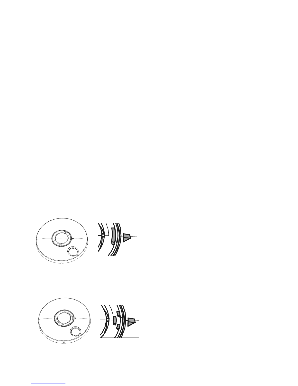
52
Special features of the terminal module 1370-10
All the switching and display functions are identical in both terminal variants 1337-XX and 1370-10. However, the
terminal module 1370-10 has a number of special features.
Destructive/non-destructive actuation of the
emergency switch
The red cap of the emer gency switch can be s et
in such a way that it remains undamaged when
actuated, or so that it is destroyed. The default status
is for non-destructive emergency switch actuation.
To change over to destructive emergency switch
actuation, the emergency switch cap must be pressed
out of the cover cowling using a suitable tool - f or
example a screwdriver - turned by 60° and replaced.
Note! When pressing out and replacing the
emergency switch cap, only exert any pressure
on the edge areas, as otherwise the centre could
unintentionally be broken out.
For precise alignment of the em ergency switch
cap, it is fitted with two markings which each have to
be aligned to a marking in the cover cowling.
Opening the cover cowling
The see-through cowling of the terminal module
1370-10 must be unlocked by turning the keyoperated switch as far as the second stopping point.
After pulling out the key, it can be removed, f or
example to reset the emergency switch.
Setting for none destructive actuation of the
emergency button
Setting for destructive actuation of the emergency
button
Page 53

53
1.5 Function variants
The functions of the em ergency exit control unit
can be varied by means of several rotary and slide
switches on the main circuit board and so adjusted in
line with the relevant application.
1.5.1 Temporary release
The duration of the temporary release can be set
between 11 and 176 seconds in 11-second steps.
The temporary release actuated with the keyoperated switch in the door terminal or the term inal
module can also be switched off completely.
(However, temporary release using the external keys
is always still possible.)
1.5.2 Permanent unlocking
Permanent unlocking via the key-operated swit ch
integrated in the door terminal or the terminal module
can be switched off.
For special applications, in which you wish to
prevent unintentional initiation of a permanent release
status, it is possible to activate a delayed acceptance
of the command. In this c ase, the comm and is only
accepted when the key is held for longer than 5
seconds in the left-hand switching position or the
relevant key of a central control panel 725 (if
connected) is actuated for longer than 5 seconds.
1.5.3 Pre-alarm
The "pre-alarm" function can be switched off. The
duration of the pre-alarm can be set between 4 and
64 seconds.
1.5.4 Alarm
The acoustic signalling of an alarm by the buzzer
integrated in the door terminal / terminal module can
be deactivated in cases where alarms are triggered
centrally. With central release and external
emergency unlocking (e.g. fire alarm control centre),
no acoustic signal is then given off at the individual
door.
The alarm causes "Emergency button", "Smoke
detector line" and "Sabotage" are, however, always
also signalled acoustically in the door terminal and
terminal module.
1.5.5 Alarm time
The acoustic alarm signal has a tim e limit. This
can be set to a value between 11 and 176 seconds.
All function and time settings at the control unit may only be performed by suitably trained or qualified
staff!
Page 54
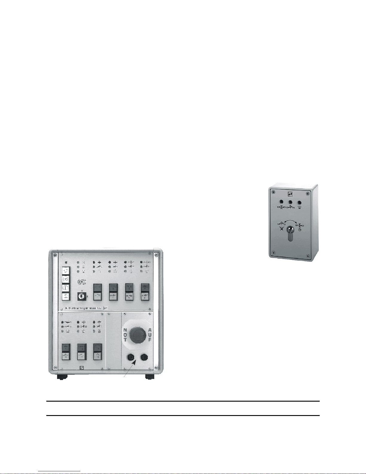
54
725 NAM-01
1.6 Special function I: Systems with indirect release. The E mergenc y Exit Control Unit
720-32
The 720-32 variant of the emergency exit control unit is a non-standard version for cases in which emergency
exits have to be released from a central location. It contains a special security relay circuit which offers the required
degree of security for this function, also for release of several doors from a central location.
All other functions of the emergency exit control unit 720-32 are identical with those of the control unit 720-
30.
This type of system is used primarily for special projects in which it is not possible to install an emergency button
at the individual doors. As a rule, the central location from which the door release f unction is initiated m ust be
permanently manned.
The operator terminal 1332-10 (Fig. 3) or the flush-mounting version 1322-11 is used as a switching and display
unit at the door. The switching and display functions of these devices - with the exception of the missing emergency
button - are identical to those of the door terminal and the terminal module.
Central EMERGENCY OPEN function
With the central emergency open function, doors are
released from a location which is not in the immediate
vicinity of the affected doors. Generally this is a
central control and monitoring panel with an
emergency button which releases all the closed
locking mechanisms when actuated.
Alarm reset
The alarm must be reset at
each individual door, even
where a central release
system is used.
For this, initially the
emergency button of the
EMERGENCY OPEN
module in the control panel
must be pulled out again. If
the emergency button is still
locked in the actuated
position, it is still possible to
acknowledge the alarm at any time by switching off
the acoustic signal, but not to reset the system.
Switching off the acoustic alarm signal
In the emergency exit control device, it is possible
to switch off the acoustic signalling of a centrally
initiated alarm at the door if it is not required.
! All function and time settings at the control unit may only be performed by suitably trained or qualified
staff!
Page 55

55
1.7 Special functions II: Oper ati on of t he emergency exit control unit using electrical
security lock 809
The effeff electrical security lock 809 is a self-locking panic lock with electrically controllable external handle and
integrated monitoring and switching contacts.
An emergency exit security system with emergency exit control unit 720-30 or 720-32 can be combined with the
effeff electrical safety lock 809 (upgrade versio n wi th four monito ring conta cts). This unit combinat ion ca n be used
to implement a series of functions which are required particularly at outside doors in certain applications.
• The closed door is always mechanically locked, as the electrical safety lock features a self-locking function
which automatically extends the bolt when the door is closed.
• It is possible to pass through the door from the inside at any time, although this is monitored effectively by
the emergency exit security system.
• The door can be passed through from the outside with a key without the use of an additional key-operated
switch. This function is initiated by the profile cylinder contact of the electrical safety lock.
• For authorized pass-through from the outside or the inside, the door can be released by actuating a button.
This actuation process can be performed from a central release key, or from an access control system or
similar.
Passing through the door from the inside
Operation of a door fitted with this type of device
combination is not different from that of a normal door
equipped with an electrical emergency exit security
system.
As the internal handle of the electrical security
lock has a panic function, this direction through the
door is only controlled by the electrical emergency
exit security system. This m ust therefore initially be
unlocked by a suitable actuation process by the
emergency exit control unit, for exam ple at the keyoperated switch of the door terminal or terminal
module, or released by a hazard warning alarm
(emergency button, fire alarm system etc.) before it is
possible to pass through the door.
Passing through the door from the
outside
The outer handle of the electrical sec urity lock is
electrically controllable. Without being actuated, it is
in the idle mode, when actuated the dead bolt and
latch bolt remain locked and the door cannot be
opened.
By means of electrical actuation, the outer handle
of the electrical security lock is connected to the lock
mechanism and then has the same functional
characteristics as the internal handle. T o be able to
pass through the door from the outside, this means
that both the electrical security lock has to be
actuated and the emergency exit control system
unlocked.
When the two control systems are combined,
these are interconnected in such a way that when the
emergency exit security system is unlocked, at the
same time the electrical security lock is actuated via
the emergency exit control device.
By means of a switching contact integrated in the
electrical security lock which is actuated by the profile
cylinder, on the other han d it is also possible to init iate
a temporary release of the emergency exit security
system. This allows the door to be passed through at
any time from the outside using a key. No additional
key-operated switch is required. If the door is opened
and closed again, it is secured by both systems
again, whereby the mechanical locked status is
retained even in case of a total f ailure of the energy
supply.
Page 56
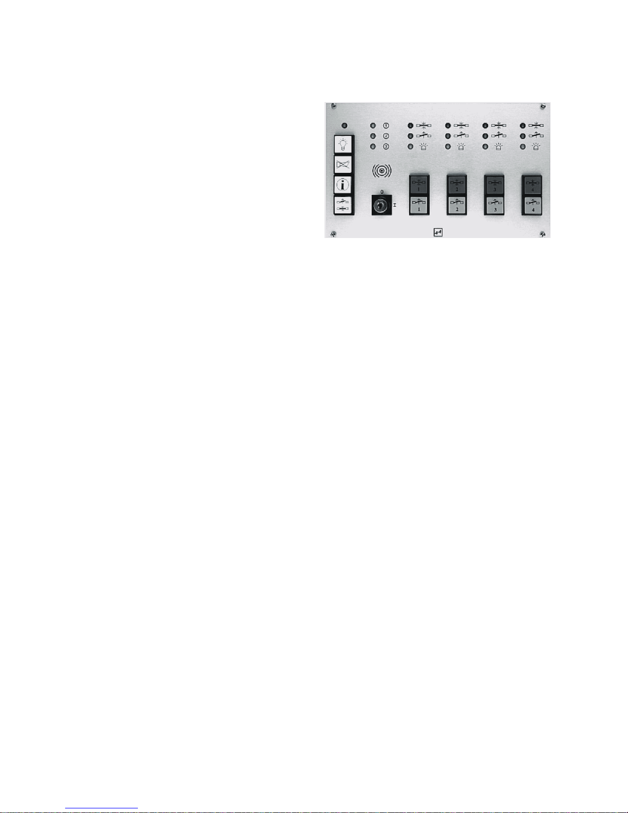
56
1.8 Special function III: O peration at the effeff do or control bus with control panel 925
Doors monitored and controlled with an emergency exit
security system wit h emergency exit control unit 720-30 or
720-32 can be jointly managed at a central display and
control panel if required.
In this case, operational control of the doors takes place
using keys integrated in the panel. The status of each
individual door is displayed - in analogy to the optical
display at the door terminal - by three LEDs.
Using this method, all functions of the em ergenc y exit
control device, including switching and display functions of
the door terminal or terminal module are retained as
described.
Details relating to the function and operation of the central panel "Bus control panel 925" are provided in
a separate set of operating instructions for the panel.
Page 57

57
1.9 Determination of an alarm condition
At door terminal 1337-xx and at the terminal module 1370-10 it is possible to determine the cause of an alarm
as long as the alarm is still active.
To do this, proceed as follows. First acknowledge the alarm by turning the key-operated swit ch at the terminal
momentarily to the left. When the alarm criterion still exists, the green LED begins to flash and the yellow LED goes
out. Subsequently turn the internal key-operated switch first to the left, then hold, and note the display at the control
terminal. Repeat the same process when turning the key to the right. The displays at the control terminal provide
an indication of the cause of the alarm . After this has been confir med, the door can be lock ed again at the keyoperated switch, i.e. the system returned to its basic status.
Table to ascertain the alarm condition:
Key-operated switch actuated after:
Criterion for actuation
Left
Right
Termi
nal LED red green yellow red green yellow
1
Sabotage at the terminal
or control unit
2
Ç
Sabotage at the door (*)
32
È
Emergency open
(was unlocked)
É
Emergency open
(was locked)
Ê
Central emergency open
(720-32)
(was unlocked)
Ë
Central emergency open
(720-32)
(was locked)
Ì
No Locked
acknowledgement
15
Í
External emergency
unlocking
(fire alarm system)
17
Î
Smoke detector line 45-46
Ï
D0019203T0000200
(*) In this case, the gre en LE D do es not flash after acknowledging the alarm. However, if the door contact remains
opened, a locking command is not accepted.
The same applies if a door-open alarm has been initiated because the door remained open too long after a
temporary release.
In case of a power failure and switch over to battery operation, the yellow LED starts to flash and the relay
for an external alarm picks up. The door remains locked.
Acknowledgement of the alarm deletes the external sign al. At the terminal, however, all switching and
display functions are retained, although the yellow LED continues to flash until the power supply is
restored.
1
The numbers in this column refer to the sect ions of the following chapter.
Page 58

58
1.10 Eliminating the reasons for the alarm
Ç Sabotage at the control unit, terminal or operator terminal
Check whether the lids of all devices are properly closed, i.e. whether the top is correctly latched into place and also
screwed to the internal housing.
È Door sabotage (*)
Check the door and correct installation of the door / monitoring contact. If the door has not been sabotaged, it may
be necessary to enlarge the latch bolt throw of the mating part slightly in the emergency exit strike.
É Ê Emergency open
To reset the emergenc y switch, the cowling must be rem oved. In the terminal module, it is released from its
anchorage by turning the key-operated switch as far as the second stop in the counter clockwise direction.
The panic button of the emergency switch is also simply pulled out in the door terminal. In the terminal module, it
must be reset by a slight turn to the left or right. After this, the required switching status can be restored using the
key-operated switch.
In the terminal module, when the emer gency switch cap is set for destructive operation, before replacing the
cowling, the cap must be renewed (see page 8).
Ë Ì Central emergency open
Initially, the central emergency open switch must be reset. After resetting, the individual doors must be switched
back to the required status.
Í No locked status acknowledgement
This message can occur, for example, if the door has not been fully closed, so that in the case of surface holding
magnets the counter holding plate is not making contact with the pole surface or the emergency exit strike is unable
to lock because a strong door seal is pres sing slightly onto its latch bolt. Ensure that the door is able to close
properly. (It may be necessary to reset the door shutter). In the case of surface holding m agnets, no external
particles may be permitted to pre ve nt the surface hold in g magnet from making flush contact with the pol e surface.
Î External emergency unlocking. (Fire alarm systems)
After acknowledging the alarm initially the external contact mus t be reset (clos ed again). After this , the r equired
switching status can be restored again at the control terminal.
Ï Smoke detector line
When a smoke detector has triggered, turn the key-operated switch of the terminal momentarily to the left twice.
After the second momentary contact pulse, the alarm is reset after around 7 seconds and the detector loop
reactivated. (Provided there is no further evidence of smoke at the detector).
Please note that most alarm signals can be triggered also by a line interruption - fo r example a cable
breakage. If a check and remedy of the above listed criteria f ail to reverse the alarm status, have the
installation checked by a specialist!
Page 59

59
2 Installation
Note!
The relevant statutory building regulations must be observed when installing and operating electrical locks
in escape routes.
The devices are in compliance with the directives applicable in the European Union relating to
electromagnetic compatibility (EMC). During electrical installation, the VDE stipulations and regulations of
the local power utility companies must be observed.
Agreement of the units with the "Directive on locking systems for doors in escape routes (EltVTR
12/97)” (Building register A part 1, no. 6.19) has been tested by TÜV Rheinland in Cologne.
Test Certificate no: R 2011393
Note!
Electrical locking sy s tems may on ly be ins talled a t s moke prote cti on or fire doors when provided for by the
application verification for the relevant door and when such systems are mounted in accordance with the
stipulations contained in it. Exception: Elements which may be mounted on already created fire doors.
Page 60
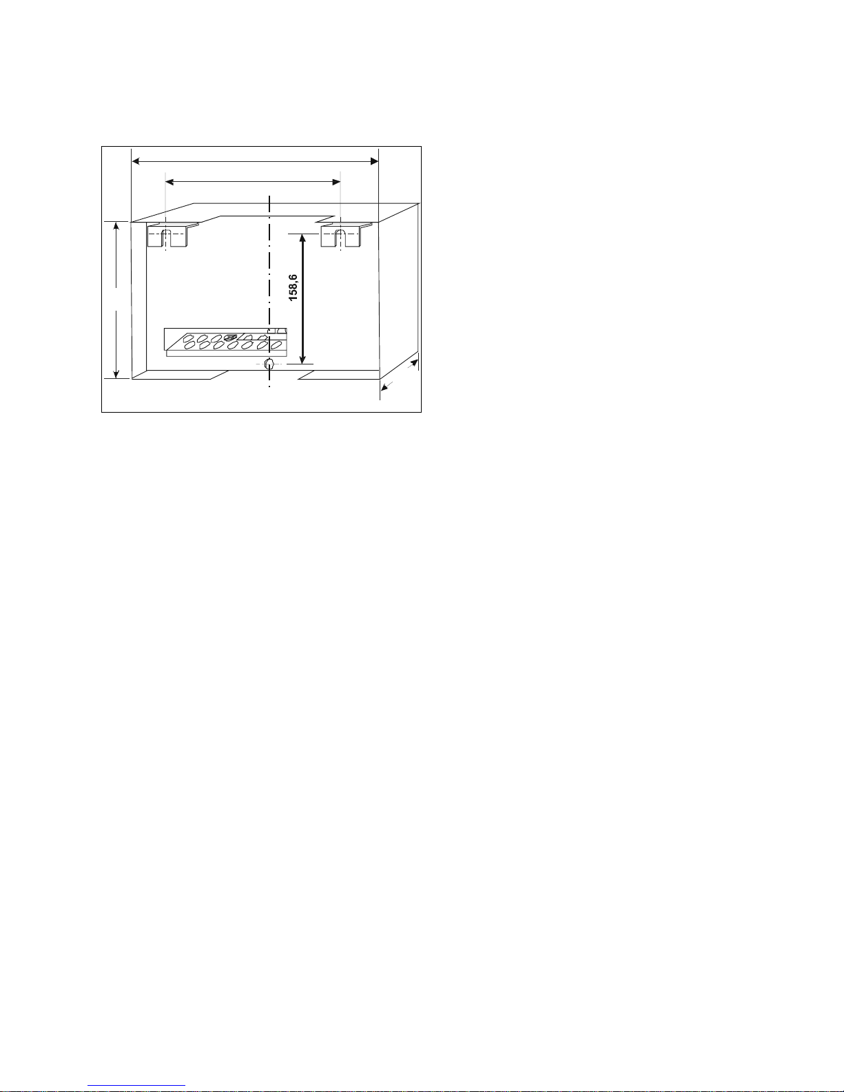
60
2.1 Mounting the control unit
The housing of the control unit is prepared for wall
mounting.
It is suspended using two screws with a 4.5 mm
diameter at the mounting brack ets and fixed using a
third screw which is screwed into the rear wall of the
housing through the bottom, central borehole.
Surface laid cables can be guided from above or below
into the housing.
The mounting position of the control unit must not
be subject to the direct influence of sunlight. When
mounting within a false ceiling, attention must be
paid to adhering to the admissible ambient
conditions in accordance with the technical data on
page 41.
225,5
300
186
125
D0019203G0000100
Page 61

61
2.2 General information on the electrical installation
Note:
Ensure correct connection. If the equipment is incorrectly connected, the warranty cover will not be
applicable.
Admissible load of the control system’s power supply unit with external devices 24 V DC: max 1.1 A
Table 3: Current consumption of devices typically connected to the control unit
Holding magnet model 828 315 mA
Emergency exit strike model 331 RR AKRR 160 mA
Swing door strike 351 AKRR 160 mA
Holding magnet model 827 250 mA
Door terminal model 1337-10/11 60 mA
Terminal module 1370-10 60 mA
Control unit model 1332-10/11 50 mA
Flash lamp model 1055-24 250 mA
Piezo horn model 1037-10 20 mA
Smoke detector model 60030 3 mA
D0019203T0000300
EMC protection:
Shielded conductors must be used. All cable shields must be mounted on one side on the
grounding bar provided in the control unit housing for this purpose.
Control cables:
Length max. 300m, minimum diameter 0.6mm.
Cables to the locking element:
Length max. 300m.
The cable cross section must be dimensioned so that a voltage of 24 V is act ive at the live lo ck ing
element.
It is possible to set an increase of the output voltage by around +10% (load-dependent) at
potentiometer PO1 to balance out the conductor loss .
All control and display elements and cables shown in dotted lines in the terminal diagrams may be
optionally connected.
Ensure adherence to the valid VDE regulations and the stipulations of the loca l energ y utility companies.
Page 62
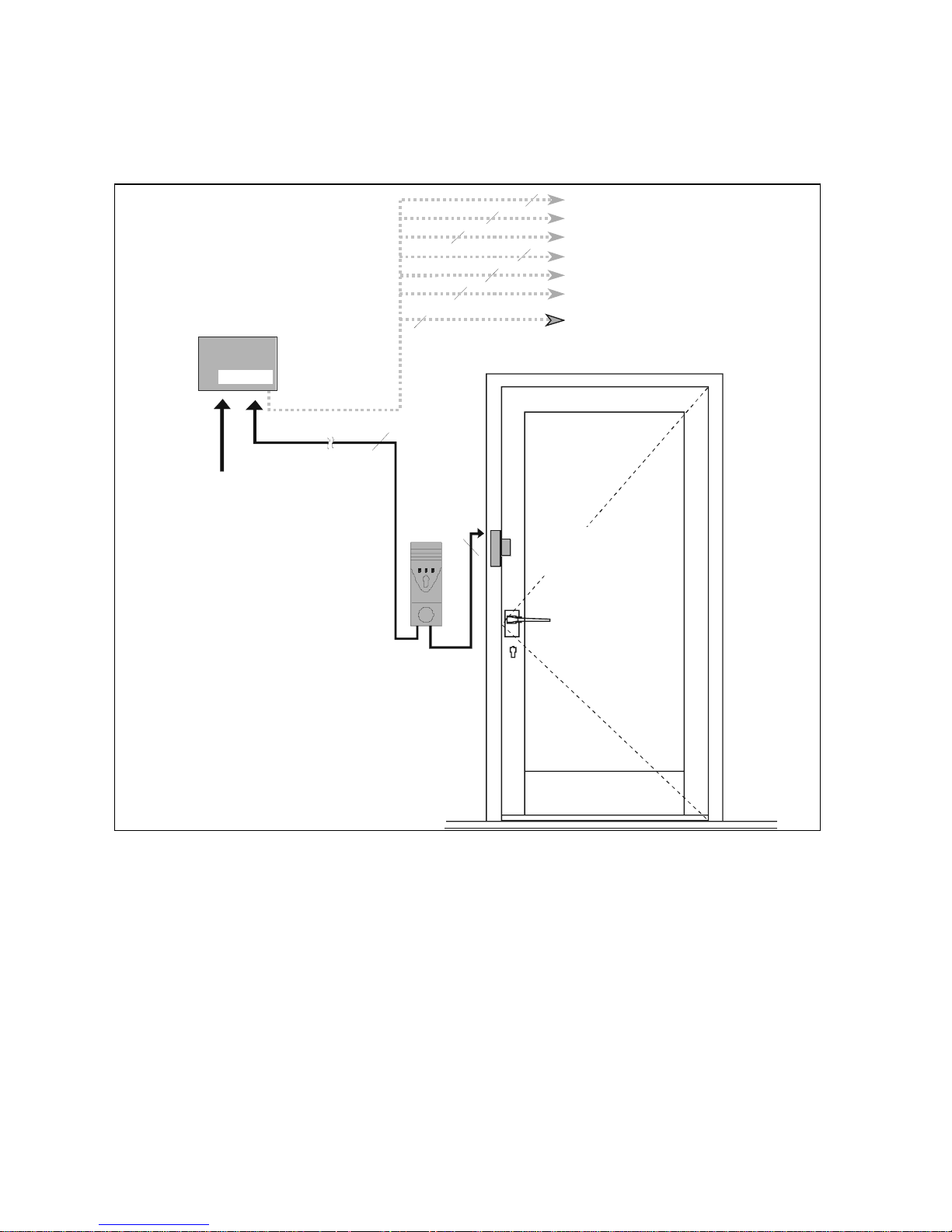
62
2.3 Cable diagrams and connection details
2.3.1 Emergency exit security system for a single-leaf door (cable diagram)
Ñ The locking elements 331 or 351 are customarily set as close to the lock as possible in order to minimize levering
forces.
Surface holding magnets are inserted transversely at the top, paying attention to adhere to the minimum clear
passage height of 2000 mm.
Ò The cable diagram is the same for both terminal variants.
720-30
230 V ± 10%
L N PE
6
16
Ò
282102
2
2
D0019203G0000200
Ñ
Smoke detector
External button, temp or ary release
Time switch
Door control panel 925 (bus technology)
Central control panel 725
Ext. emer gency unloc king
(e.g. fire alarm system)
Operator terminal 13 32-10/11
Emergency exit control unit
Door terminal
or
terminal m odule
Locking element
(model 331 RR AKRR with
counterelement mod el 807-10
or model 351 RR AKRR)
Page 63
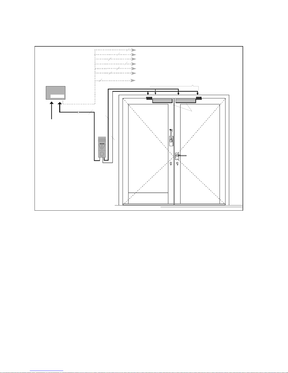
63
2.3.2 Emergency exit security system for a two-leaf emergency exit (cable diagram)
Ñ On two-leaf doors, a locking elem ent mus t be used in each leaf . Any of the em ergenc y exit lock ing elem ents
offered in the effeff range can be used.
When using the surface holding magnets, pay attention to adhere to the minimum clear passage height of
2000 mm.
Ò When using emergency exit strike 331 RR AKRR or swing door strike 351 RR AKRR, there is no need to mount
door contacts, as these are already integrated in the strike.
Ó The cable diagram is the same for terminal variants.
720-30
4
16
2
2
8
10
2
2
2
2
Türkontakte
Ñ
Ò
D0019203G0000300
Ó
Smoke detector
External button, temporary release
Time switch
Door control panel 925 (bus technology)
Central control panel 725
Ext. emer gency unlocking
(e.g. fire alarm system)
Operator terminal 1332-10/11
230 V ± 10%
L N PE
Door terminal
or
terminal m odule
Emergency exit control unit
Locking elements
Page 64
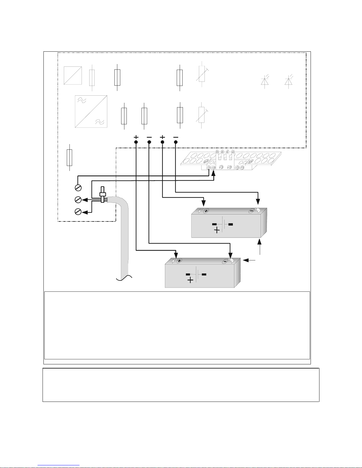
64
2.3.3 Mains and battery connection
Note!
When supplying the device with external voltage via terminals 25-26, no mains supply line may be
connected. In this case, no batteries may be connected. Switch S 5.6 must be in the "off" position. The
power supply unit must be in compliance with DIN EN 60950!
Intrinsic current consumption of the control system: 150 mA.
=
F 1
0,5 A T
F 2
2 A T
F 3
1,25 A T
F 6
1,25 A T
F 5
1,25 A T
L 1
N
PE
L 1, N, PE;
3 x 1,5 mm
2
AK 1
AK 2
12 V / 2 Ah
12 V / 2 Ah
PO 1
24 V + 10%
PO 2
LED “NT”
LED “AK”
Ñ
Ò
Ó
Ô
Õ
Ö
F 7
0,1 A T
F 4
1,25 A T
D0019203A0000100
For connection of the mains supply cable:
To adhere to the low-voltage directive (DIN-EN 60950), the following points must be observed when
connecting the mains cable:
1. Remove the sheathing on the mains cable to
around 15 cm
2. Shorten the black and blue cores to around 3 cm
3. Strip all three cores to around 8 mm
4. Guide the black core to terminal L and the blue
core to terminal N and connect, bringing the sheath
up as close as possible to the terminals.
5. Bend over the green/yellow core, guide to the
grounding bar and connect.
6. Use the cable binder to fix and bind the three cores as
close to the terminals as possible.
Output voltage
Setting range
(grn)
(yellow)
Battery charge voltage
Red / black
Red / black
Red
Red
Battery1
Battery2
Mains supply cable
Page 65

65
Remarks relating to page 20
Ñ Mains connection and wiring
All terminals should be kept as short as possible. The PE conductor must be laid to the grounding bar of the housing. A
connection is already created between the grounding bar and the PE in the factory.
The device must be configured to permit isolation from the supply circuit by means of an easily accessible isolating
device.
Ò Potentiometer PO 1
Using PO 1, the output voltage for the locking element can be adjusted. This may become possible in cases where, due to the
greater conductor lengths between the control unit and locking element, appreciable conductor losses occur. The voltage may
have to be adjusted in such cases so that 24 Volts are applied to the locking element when activated.
Ó Potentiometer PO 2
PO 2 is used to set the battery charge voltage. This is set precisely in the factory for each device.
PO 2 may not be adjusted under any circumstances!
Ô Batteries 12 V, 2 Ah
The device can also be operated without batteries. However, when batteries are connected, only the 12 V, 2 Ah lead batteries
offered by effeff under the order number 18002 may be used.
The batteries are installed in the compartment in front of the terminals on the floor of the housing.
The batterie s mu st be checked at regul ar intervals by operating in the em er gency power mod e fo r 15 min utes. After switching
the mains power supply back on, the control unit must assume operating status I in accordance with Table 4. If the display fails
to change within three seconds to operating status II or I, the device must be briefly isolated from the mains supply and
switched back on. After this, operating status II or I must be reached again within 10 minutes. If this fails to happen, the
connected batteries are defective.
Õ LED displays on the circuit board:
LED “NT”
green
LED “AK”
yellow
Operating status Remarks
ON OFF
(I) Mains operation. U
Batt
>
Cut-off voltage
After the yellow LED goes out, the
battery is charged within 24 hours to 80%
of its rated capacity
ON
Slow blinking
1:1
(II) Mains operation. 12 V < U
BATT
< Cut-off
voltage The batteries are being charged
ON ON
(III) Mains operation. U
BATT
< 12 V or missing
The batteries are exhaustively
discharged, defective or not connected
OFF flashing
(IV) Battery operation (mains failure where
batteries are fitted)
With charged batteries, a bridging time of
at least 15 mins. is guaranteed
OFF OFF
(V) external 24V supply (no mains, no
batteries)
S 5.6 must be in the "off" position (see
page 36)
ON
Fast blinking
1:1
(VI) Short circuit at battery terminals
Table 4: LED display on main circuit board D0019203T0000400
Ö Grounding bar in the housing
In the housing directly under the cable inlet and firmly connected to the cable fixing web is the grounding bar. This is already
connected to the PE terminal in the factory. The PE conductor of the mains supply cable must be laid to the second screw-type
terminal for the grounding bar.
The cable shields of all incoming cables must be laid to this grounding bar.
Fuses:
F 1 Primary fuse, transformer 0.5 AT
F 2 Secondary fuse, transformer 2 AT
F 3 Input fuse control unit 720-30/32 1.25 AT
F 4 Input fuse external power supply (terminals 25-26) 1.25 AT
F 5, F 6 battery fuses 1.25 AT
F 7 Supply to the electronic evaluator, holding magnet
(terminal 14) 0,1 AT
Page 66
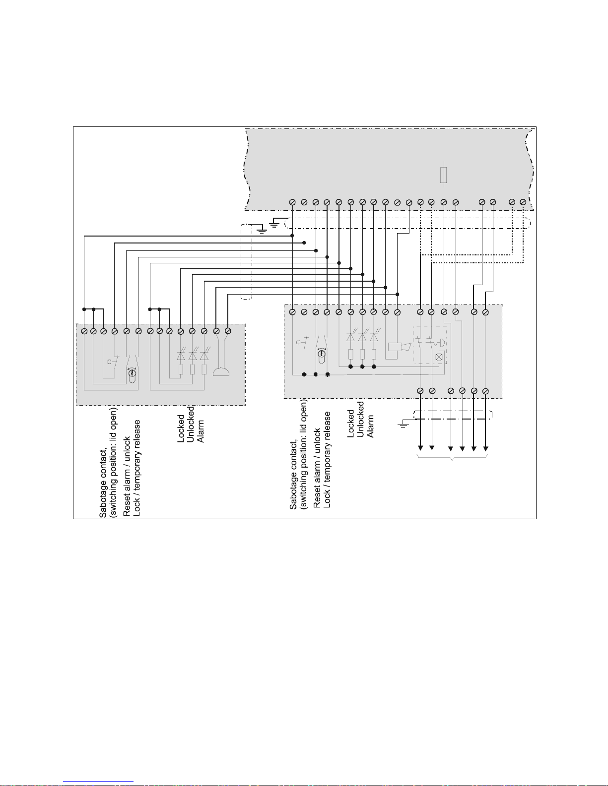
66
2.4 Locking systems with the door terminal 1337-10/11
2.4.1 Connection detail parallel connection control unit 1332 and door terminal 1337-10/11
12 14 19
202122
1
23456789101112131415313247
48
1
23456789
10111315161718
1310 7 9 1114 4 6 5 2 3 1 16 17
rdrdgngnyeye720-30
720-32
D0019203A0000200
Emergency exit control unit 720-30/32
Operator terminal 1332-10/11
Buzzer
Door terminal 1337-10/11
Locking element connection,
see overall terminal plan
Page 67
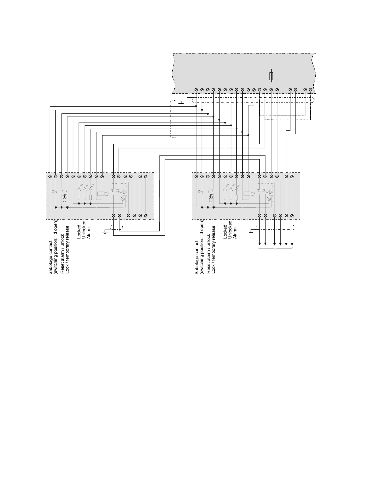
67
2.4.2 Connection detail: Parallel connection of two door terminals 1337-10/11
1214192021
22
12345678910111213141531324748
123456789
10111315161718rdgn
ye
720-30
720-32
Emergency exit control unit 720-30/32
Door terminal 1337-10/11
Locking elem ent conn ect io n,
see overall terminal plan
12 14 19 20 21 22
12345678910 1113
rd gn ye
Door terminal 1337-10/11
D0019203A0000300
Page 68
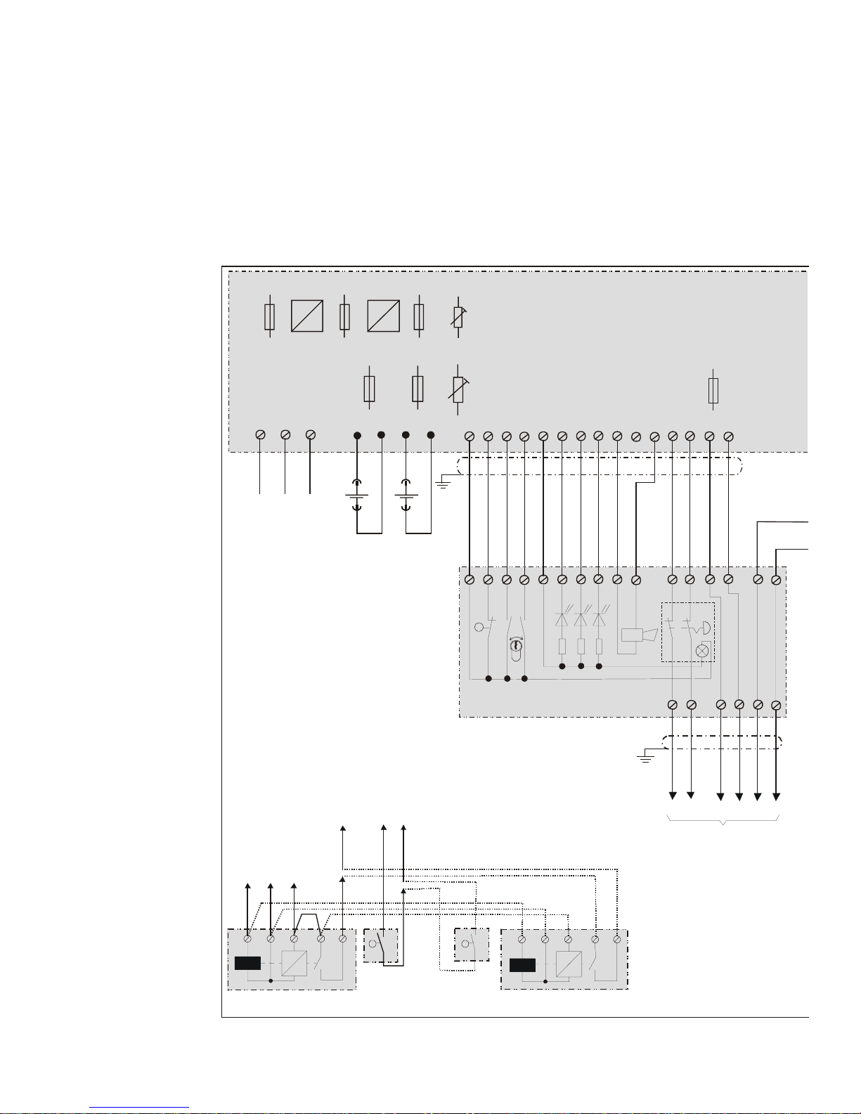
68
2.4.3 Overall terminal diagram 720-30 with door terminal 1337-10/11
»
»
»
=
++--
56432
564 32
AB
DEF
C
230 V / 50-60 Hz
L1 N PE
12 14 19 20 21 22
1 2 3 4 5 6 7 8 9 10 11 12 13 14 15
1 23456 78910 11131516 1718
rd gn ye
Door terminal 1337-10/11
Emergency exit control unit 720-30
Note:
When two locking elements are
connected to the control unit
(e.g. in the case of two-leafed doors),
both the door contact and the locked
status monitors (armature contact /
Hall element) must be switched
. in series
Mains voltage
Battery
12 V, 2 AH
Battery
12 V, 2 AH
Locking element connection,
see below
Sabotage contact,
(switching position: lid open)
Reset alarm / unlock
Lock / temporary release
Locked
Unlocked
Alarm
Holding magnet
model 828 24 V
Holding magnet
model 828 24 V
Door
contact
Door
contact
AB CDEF
L1 N PE
F 1
0,5 AT
F 2
2 AT
F 3
1,25 AT
F 5
1,25 AT
F 6
1,25 AT
Setting range
Output voltage
24 V +10%
PO 1
PO 2
F 7
0,1 AT
AK 1 AK 2
Battery charge voltage
(See operating instructions)
Page 69
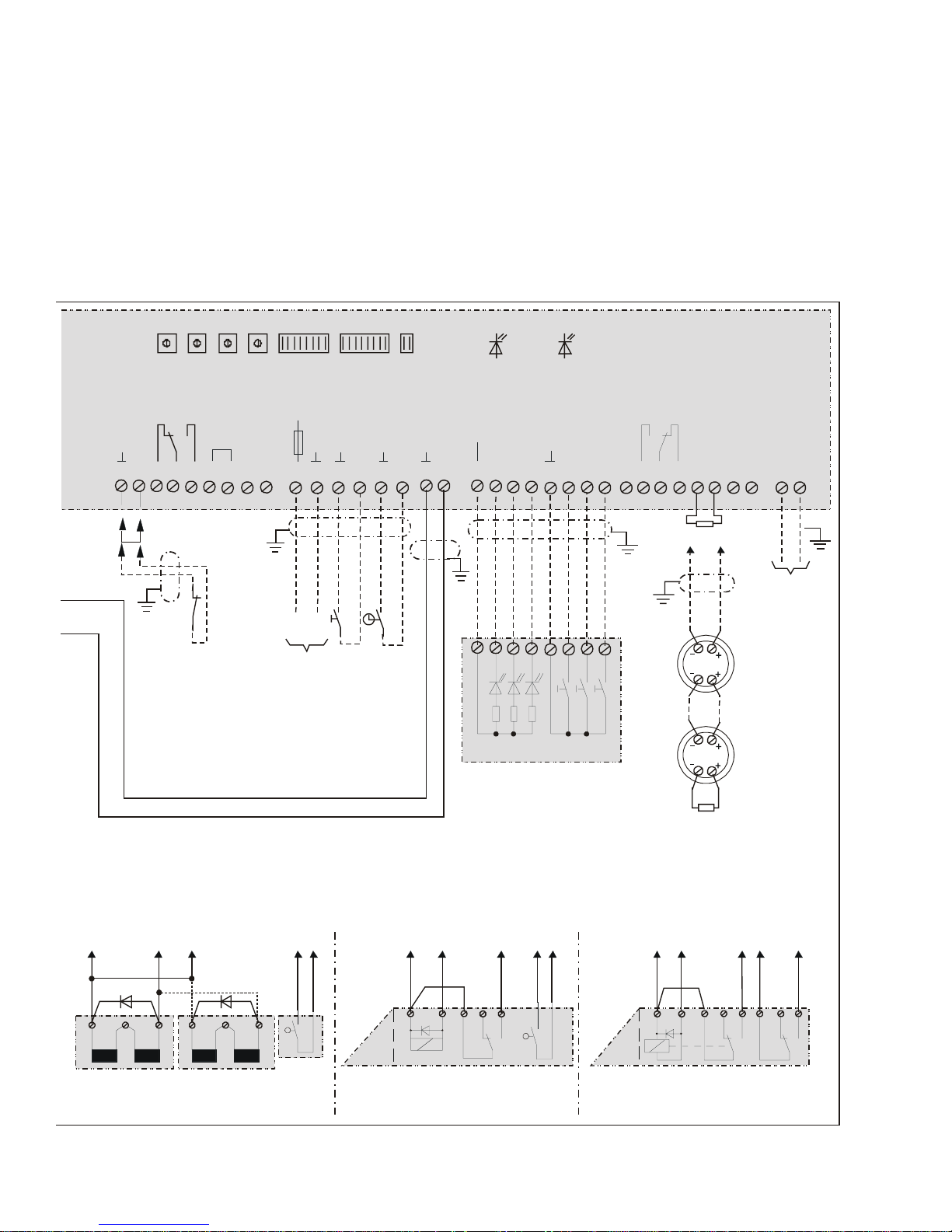
69
F 4
1,25AT
+
-
A
B
+UB
rd gn ye
Relais 5
max. 24 V, 1A
Relais 4
Alarmrelais
max. 24 V, 1A
BM
BM
LED “NT”
green
2,43 K
ye ye
gn gnbr br
wt wt
ABD EF AB DEF
bl
gn gn
rd
rd
rd bl
A
BDEF
LED “AK”
yellow
7 4568 3 2 1
D0019203A0000400
For switch assignment and settings,
see operating instructions
S1 S2 S3 S4 S5 S6 S7
ON
OFF
Data
0 V
unlocked
locked
16 17 18 19 20 21 22 23 24 25 26 27 28 29 30 31 32 33 34 35 36 37 38 39 40 41 42 43 44 45 46 47 48
24 V
0 V
Locked
Unlocked
Alarm
Central panel 725 …
Central release
Lock
Unlock
Ext. operating
voltage 24 V DC
Detector n
Detector 1
2,43K
Smoke detektor
loop
Bus terminals
effeff TS-Bus
Temporary release
(push button,
access control device)
Permanent unlocking
(clock/switch)
Ext. emergency unlocking
(e.g. ire alarm system)
bl = blue
rd = red
wt = white
br = brown
gn = green
ye = yellow
Holding magnet
model 827 24 V
Holding magnet
model 827 24 V
Door
contact
Swing door release
model 351 RR AKRR
Armature
contact
Armature
contact
Door contact
“RR” contact
Door contact
“RR” contact
Emergency exit release
model 331 RR AK RR
blgnrdrd bl blgnrd
Page 70
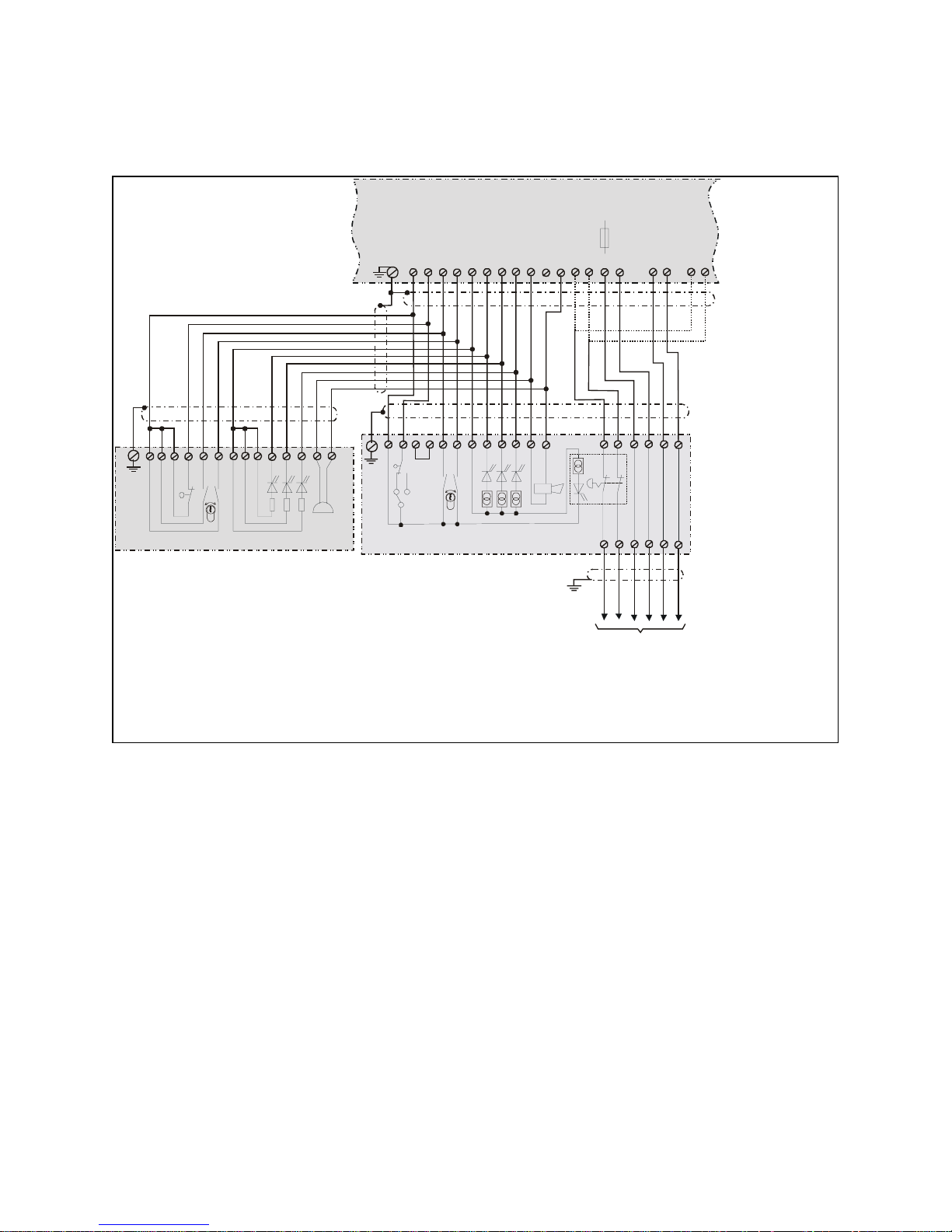
70
2.5 Locking systems with terminal module 1370-10
2.5.1 Connection detail: Terminal module 1370-10 with operator terminal 1332
ΠThe control unit and terminal module must be connected via the cable shields. However, these must only be
grounded on one side (at the control unit).
The shields of all conductors occurring at the control unit must be connected here to the grounding bar. They may
only be grounded on one side.
Ž Jumper J1
The sabotage contact of the terminal module can be set as a n.c. or n.o. contact using jumper J1. In the control unit
720-30 it must be set as a n.o. contact.
For this reason, it must be plugged over to position 2-3. Note: The status on delivery is position 2-1!
1310 7 9 11 14 4 6 5 2 3 1 16 17
rd gn ye
Emergency exit control unit 720-30/32
Operator terminal 1332-10/11
Buzzer
D0019203A0000500
rd gn ye
720-30 720-32
Terminal module 1370-10/11
Locking element connection,
see overall terminal plan
16
23 17 18 22 19 20 21 14 13
123456
1
2 3 4 5 6 7 8 9 10 11 12 13 14 15 31 32 47 48
789101112
3
1
2
SK
J1
Locked
Locked
Unlocked
Unlocked
Alarm
Alarm
Sabotage contact,
(switching position: lid open)
Sabotage contact,
(switching position: lid open)
Reset alarm / unlock
Reset alarm / unlock
Lock / temporary release
Lock / temporary release
Page 71

71
2.5.2 Connection detail parallel connection of two terminal modules 1370-10
The control unit and terminal module must be connected via the cable shields. However, these must only be
grounded on one side (at the control unit).
The shields of all conductors occurring at the control unit must be connected here to the grounding bar. They may
only be grounded on one side.
Jumper J1
The sabotage contact of the terminal module can be set as a n.c. or n.o. contact using jumper J1. In the control unit
720-30 it must be set as a n.o. contact.
For this reason, it must be plugged over to position 2-3. Note: The status on delivery is position 2-1
Emergency exit control unit 720-30/32
D0019203A0000600
rdrd gngn yeye
720-30 720-32
Terminal module 1370-10/11Terminal module 1370-10/11
Locking element connection,
see overall terminal plan
16
23 17 18 22 19 20 21 14 13
16
23 17 18 22 19 20 21 14 13
123456123456
1
2 3 4 5 6 7 8 9 10 11 12 13 14 15 31 32 47 48
789101112789101112
3
1
2
SK
J1
3
1
2
SK
J1
Locked
Locked
Unlocked
Unlocked
Alarm
Alarm
Sabotage contact,
(switching position: lid open)
Sabotage contact,
(switching position: lid open)
Reset alarm / unlock
Reset alarm / unlock
Lock / temporary release
Lock / temporary release
Page 72
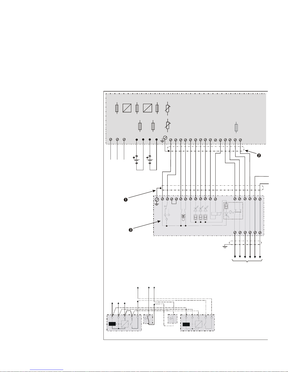
72
2.5.3 Overall terminal diagram 720-30 with terminal module 1370-10
ìThe control unit and
terminal module must be
connected via the cable
shields. However, these
must only be grounded on
one side (at the control
unit).
íThe shields of all
conductors occurring at
the control unit must be
connected here to the
grounding bar. They may
only be grounded on one
side.
îJumper J1
The sabotage contact o
f
the terminal module can
be set as a n.c. or n.o.
contact using jumper J1.
In the control unit 720-30
it must be set as a n.o.
contact.
For this reason, it must
be plugged over to
position 2-3. Note: The
status on delivery is
position 2-1!
rd gn ye
Terminal module 1370-10/11
Locking element
connection,
16
23 17 18 22 19 20 21 14 13 1 2 3 4 5 6
789101112
3
1
2
SK
J1
Locked
Unlocked
Alarm
Sabotage contact,
(switching position: lid open)
Reset alarm / unlock
Lock / temporary release
»
»
»
=
+-+-
230 V / 50-60 Hz
L1 N PE
L1 N PE
1
2 3 4 5 6 7 8 9 10 11 12 13 14 15
Emergency exit control unit 720-30
Note:
When two locking elements
are connected to the control
unit (e.g. in the case of
two-leafed doors), both the door
contact and the locked status
monitors (armature contact /
Hall element) must be switched
. in ser ies
Battery charge voltage
(See operating instructions)
Mains voltage
Battery
12 V, 2 AH
Battery
12 V, 2 AH
56432
564 32
AB
DEF
C
Holding magnet
model 828, 24 V
Holding magnet
model 828, 24 V
Door
contact
Door
contact
F 1
0,5 AT
F 2
2 AT
F 3
1,25 AT
F 5
1,25 AT
F 6
1,25 AT
Setting range
Output voltage
24 V +10%
PO 1
PO 2
F 7
0,1 AT
AK 1 AK 2
Page 73
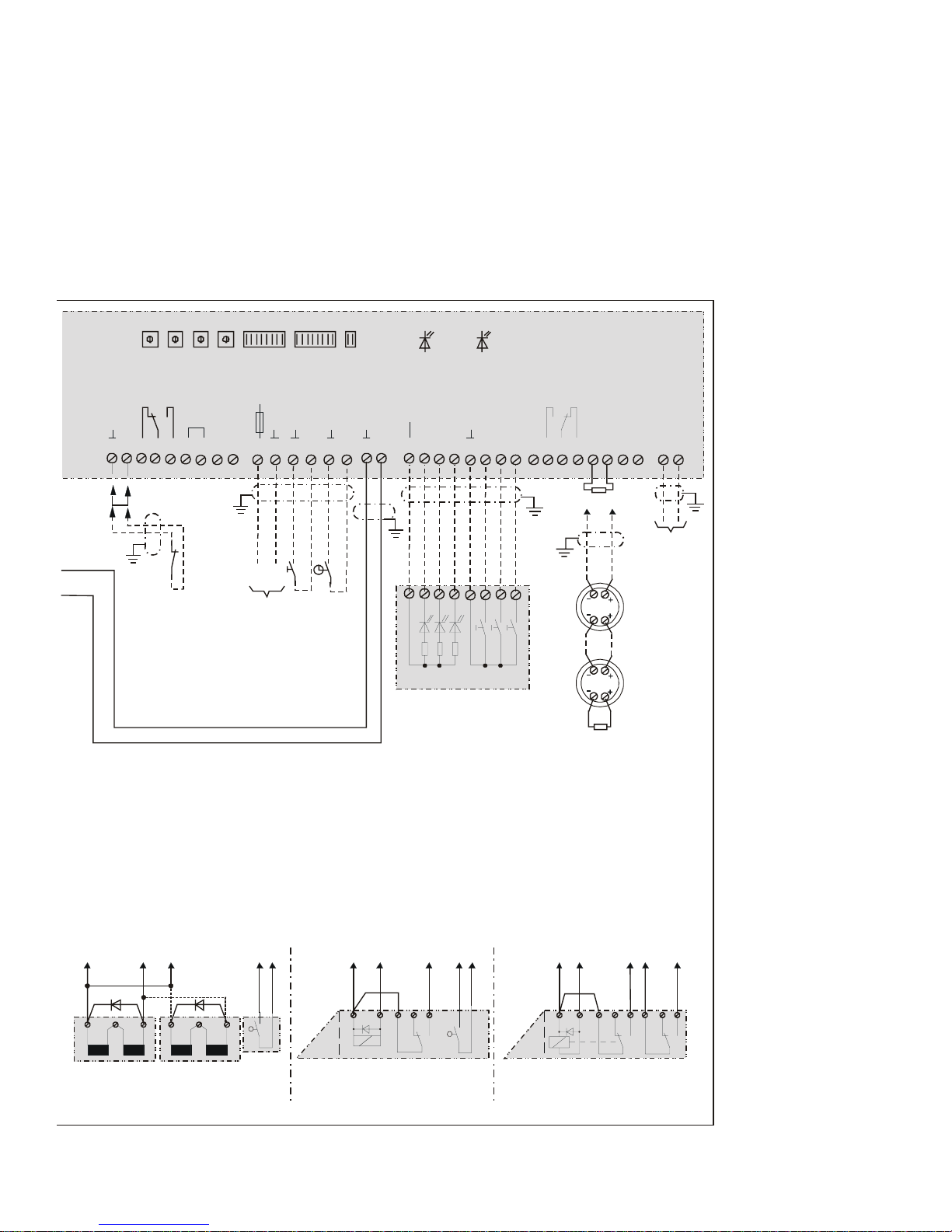
73
F 4
1,25AT
+
-
A
B
+UB
rdgnye
Relais 5
max. 24 V, 1A
Relais 4
Alarmrelais
max. 24 V, 1A
BM
BM
LED “NT”
green
2,43 K
ye ye
gn gnbr brwt wt
ABD EF AB D EF
bl
gn gn
rd
rd
rd bl
A
BDEF
LED “AK”
yellow
7 456832 1
D0019203A0000700
For switch assi
g
nment and settings,
see operating instructions
S1 S2 S3 S4 S5 S6 S7
ON
OFF
Data
0 V
unlocked
locked
16 17 18 19 20 21 22 23 24 25 26 27 28 29 30 31 32 33 34 35 36 37 38 39 40 41 42 43 44 45 46 47 48
24 V
0 V
Locked
Unlocked
Alarm
Central panel 725 …
Central release
Lock
Unlock
Ext. operating
voltage 24 V DC
Detector n
Detector 1
2,43K
Smoke detektor
loop
Bus terminals
effeff TS-Bus
Temporary release
(push button,
access control device)
Permanent unlocking
(clock/switch)
Ext.. emergency unlocking
(e.g. fire alarm system)
bl = blue
rd = red
wt = white
br = brown
gn = green
ye = yellow
Holding magnet
model 827 24 V
Holdin
g
magnet
model 827 24 V
Door
contact
Swing door release
model 351 RR AKRR
Armature
contact
Armature
contact
Door contact
“RR” contact
Door contact
“RR” contact
Emergency exit release
model 331 RR AK RR
blgnrdrd bl blgnrd
Page 74

74
2.6 Systems with indirect (central) release (special function I)
If indirect (central) release of all doors is required in a system with several emergency exits using only a single
emergency switch actuation, the control unit model 720-32 must be used. This control unit is equipped with a safety
relay circuit through whose contacts current is applied to the relevant locking element. The positively driven contacts
of the three safety relays which make up the circuit are linked in such a way that in case of a fault, for example
welded contacts or a spring breakage, re-activation of the locked status is prevented.
In this case, the power supply to the safety relay for all the doors is routed via an emergency button model 725 NAM01 with bipolar cut-out in case of emergency.
Up to a maximum of 20 doors can be switched using an emergency cut-out module 725-NAM-01.
Overall current consumption of the safety relay circuit per control unit 720-32: appr. 110 mA
Page 75
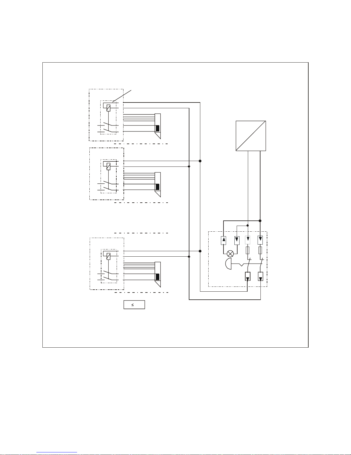
75
2.6.1 Terminal diagram, indirect (central) release
+
–
24 V DC
Door 2
23
24
47
48
720-32
2control unit
+
–
23
24
47
48
720-32
control unit 1
Security relais circuit
(principle circuit diagram)
+
–
Door 1
Door n
23
24
47
48
720-32
n
control unit
+
–
Emercency switch off
Modul
725-NAM-01
External power supply
in complyance with DIN EN 60950
D0019203A0000800
n 20 !
Current consumption of the security relais circuit: 110 mA
Page 76
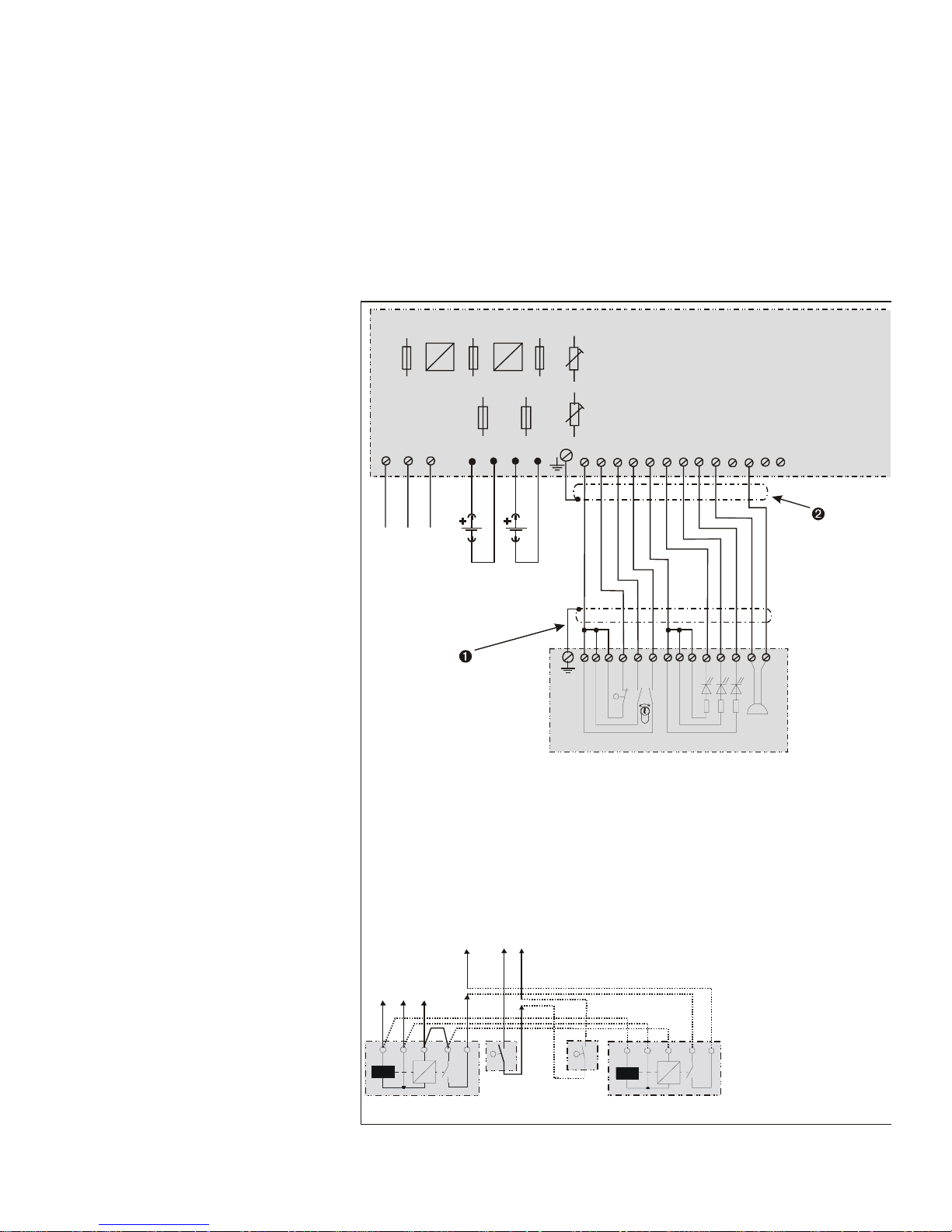
76
2.6.2 Overall terminal diagram 720-32
ìThe control unit and
terminal module must be
connected via the cable
shields. However, these
must only be grounded on
one side (at the control
unit).
íThe shields of all
conductors occurring at
the control unit must be
connected here to the
grounding bar. They may
only be grounded on one
side.
1310 7 9 11 14 4 6 5 2 3 1 16 17
rd gn ye
Operator terminal 1332-10/11
Buzzer
Locked
Unlocked
Alarm
Sabotage contact,
(switching position: lid open)
Reset alarm / unlock
Lock / temporary release
»
»
»
=
+-+-
230 V / 50-60 Hz
L1 N PE
L1 N PE
1
2 3 4 5 6 7 8 9 10 11 12 13
Emergency exit control unit 720-32
Battery charge voltage
(See operating instructions)
Mains voltage
Battery
12 V, 2 AH
Battery
12 V, 2 AH
56432
564 32
AB
DEF
C
Holding magnet
model 828, 24 V
Holding magnet
model 828, 24 V
Door
contact
Door
contact
F 1
0,5 AT
F 2
2 AT
F 3
1,25 AT
F 5
1,25 AT
F 6
1,25 AT
Setting range
Output voltage
24 V +10%
PO 1
PO 2
AK 1 AK 2
Note:
When two locking elements
are connected to the control
unit (e.g. in the case of
two-leafed doors), both the door
contact and the locked status
monitors (armature contact /
Hall element) must be switched
. in ser ies
Page 77
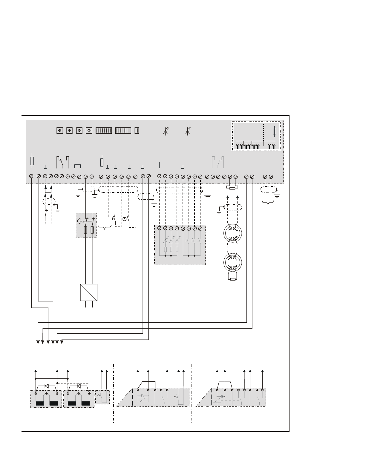
77
F 4
1,25AT
+
-
+UB
rdgnye
Relais 5
max. 24 V, 1A
Relais 4
Alarmrelais
max. 24 V, 1A
BM
BM
LED “NT”
green
2,43 K
ye ye
gn gnbr br
wt wt
ABD EF AB DEF
bl
gn gn
rd
rd
rd bl
A
BDEF
LED “AK”
yellow
7456832 1
D0019203A0000900
For switch assi
g
nment and settings,
see operating instructions
S1 S2 S3 S4 S5 S6 S7
ON
OFF
unlocked
locked
16 17 18 19 20 21 22 23 24 25 26 27 28 29 30 31 32 33 34 35 36 37 38 39 40 41 42 43 44 45 46 47 48
24 V
0 V
Locked
Unlocked
Alarm
Central panel 725 …
Central release
Lock
Unlock
Ext. operating
voltage 24 V DC
Detector n
Detector 1
2,43K
Smoke detektor
loop
AB
Data
0 V
Bus terminals
effeff TS-Bus
Temporary release
(push button,
access control device)
Permanent unlocking
(clock/switch)
Ext.. emergency unlocking
(e.g. fire alarm system)
bl = blue
rd = red
wt = white
br = brown
gn = green
ye = yellow
Holding magnet
model 827 24 V
Holdin
g
magnet
model 827 24 V
Door
contact
Swing door release
model 351 RR AKRR
Armature
contact
Armature
contact
Door contact
“RR” contact
Door contact
“RR” contact
Emergency exit release
model 331 RR AK RR
blgnrdrd bl blgnrd
SicherheitsRelaisschaltung
720.22-92-02
F 1
0,16 AT
14 15
F 7
0,1 AT
Mains
230 V AC /50 Hz
ABCDEF
Central emercency open
module 725 NAM
Page 78
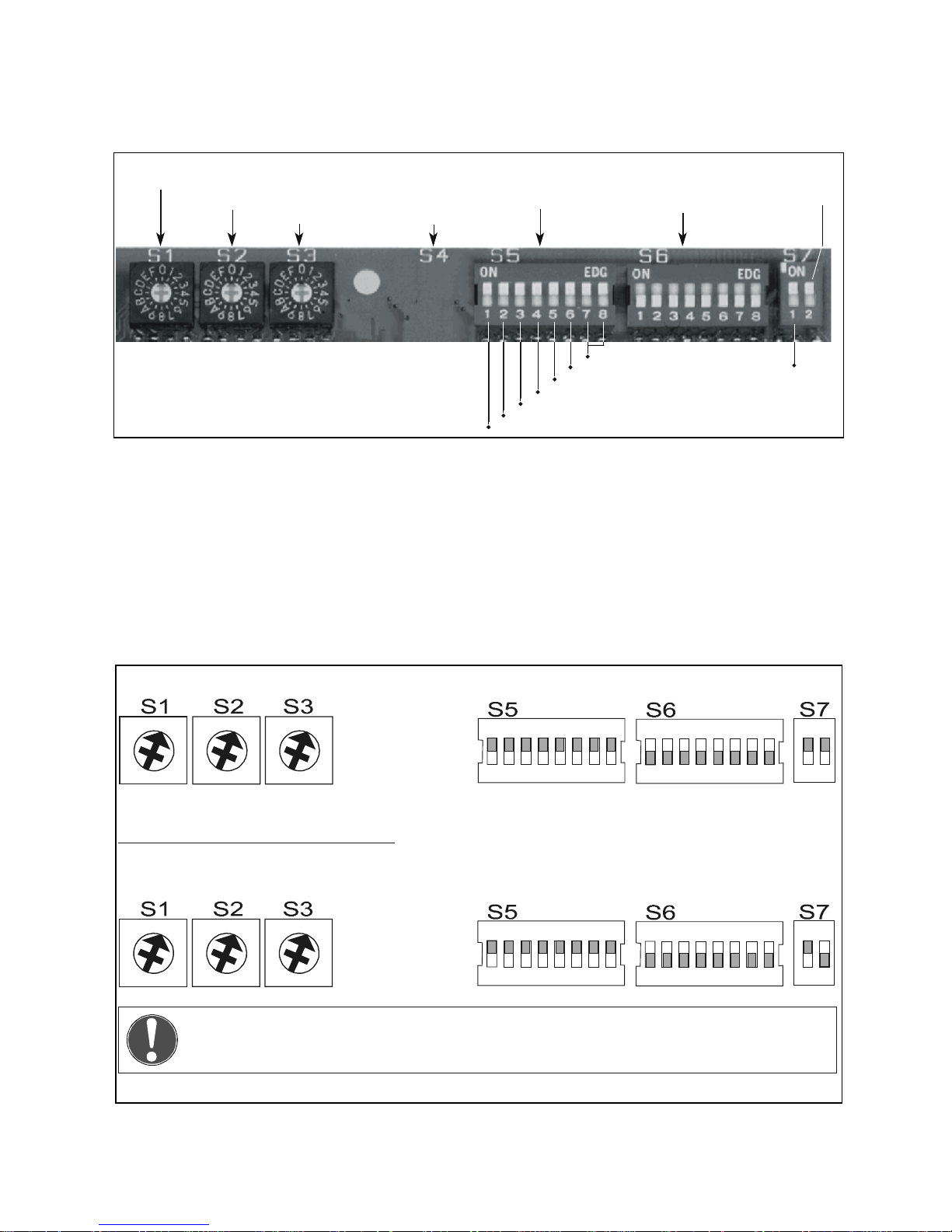
78
2.7 Setting switches for functions and time sequences
Using setting switches S 1 to S 7 it is possible to presc ribe the duration of tim e sequenc es controlled by the
emergency exit control unit and also variants for the switching and alarm functions.
2.7.1 Default positions of setting switches
Note!
Switches S 5.7 and S 5.8 must not be moved!
They must both remain in “ON”-position in both variants of the device!
0
1
2
3
4
5
6
7
8
9
A
B
C
D
E
F
0
1
2
3
4
5
6
7
8
9
A
B
C
D
E
F
0
1
2
3
4
5
6
7
8
9
A
B
C
D
E
F
0
1
2
3
4
5
6
7
8
9
A
B
C
D
E
F
0
1
2
3
4
5
6
7
8
9
A
B
C
D
E
F
0
1
2
3
4
5
6
7
8
9
A
B
C
D
E
F
21
('*
21
('*
21
21
('*
21
('*
21
720-30
720-32
D0019203G0000500
D0019203G0000400
Time setting for
temporary release
Pre-alarm time
Alarm time
S 4
not mounted
Functional variants
Bus address
Must be in position “ON”
when security relais board
is mounted
not
Prealarm
without function
battery monitoring
permanent unlockin g
acoustic alarm in door terminal
permanent unlocking without delay
temporary release
door monitoring
Page 79

79
2.7.2 Time inputs
S 1 Temporary release time
With rotary switch S1, the door unlocked duration is
defined for the temporary release function. If the door
is not opened during the prescribed time, it is locked
again. Closing the door interrupts the time sequence,
meaning that it is immediately locked again.
If the door is still open after expiry of the time
entered at S1, the pre-alarm and then the alarm ar e
initiated provided the "Door monitoring" function has
not been switched off.
Switch position 0: 11 Seconds
Time increments: 11 Seconds
Switch position F: 176 Seconds
S 2 Pre-alarm time
Rotary switch S2 indicates the duration of the prealarm. If the door is not clos ed, after expiry of this
time an alarm is triggered.
Switch position 0: 4 Seconds
Time increments: 4 Seconds
Switch position F: 64 Seconds
S 3 Alarm time
After expiry of the time set at S 3, the acoustic
alarm signal is switched off. However, alarm
signalling in the form of the yellow LED and the alarm
relay (terminals 42 to 44) remains until the alarm is
acknowledged and reset.
Switch position 0: 11 Seconds
Time increments: 11 Seconds
Switch position F: 176 Seconds
S 4
Switch S 4 is not assigned.
2.7.3 S 5 function variants
Using the slide switches of the switch block S5, different switching and monitoring functions of the control system
can be switched on or off.
S 5.1 Door monitoring
Switch position “on”: The door is monitor ed for a
maximum admissible open time. (See also
"Temporary release time" and "Pre-alarm time”!)
Switch position “off”: The door open time after
temporary release or after term ination of per m anent
unlocking when the door is open is not monitored. A
door remaining open does not initiate an alarm.
S 5.2 Temporary release
Switch S 5.2 only influences the function of the
control input terminal 4 (turn of the key to the right at
the door terminal or terminal module).
In the "On" switch position and with the door
locked, a momentary contact pulse at this input
initiates a temporary release. (see above!)
In the "Off" switching position, only the control
command "lock" can be issued at terminal 4.
Temporary release via terminals 27 and 28 is not
influenced by the position of S 5.2.
S 5.3 Permanent unlocking, no delay
Switch S 5.3 influences the function of the control
input terminal 3 (turning the key to the left at the
terminal) and terminal 40 (central panel).
In the "On" switch position, a continuous unlocking
command is accepted without delay.
In the "Off" switch position, a continuous unlocking
command is ac cepted only if the signal is active f or
longer than 5 seconds.
The function of the control input "Permanent
unlocking" at terminals 29 and 30 is not influenced by
the position of S 5.3.
Page 80

80
S 5.4 Acoustic alarm
Using this switch, the acoustic alarm signal in the
door terminal or terminal module can be switched off
in case of a centrally triggered alarm.
In the "On" switch position, every alarm is also
signalled acoustically in the terminal.
In the "Off" switch position, the causes of alarms:
-Ext. emergency unlocking
-Central emergency open (720-32)
-Central release terminal 38
are not acoustically signalled at the terminal.
S 5.5 Permanent unlocking
Switch S 5.5 influences only the function of the
control input terminal 3.
In the "On" switch position, continuous unlock ing is
possible using the key -operat ed switch in the terminal.
In the "Off" switch position, it is not possible to trigger
a permanent unlocking status from the terminal.
The "permanent unlocking" control input (terminals
29-30) is not influenced by the position of S 5.5.
S 5.6 Battery monitori ng
Sliding switch S 5.6 must be used in cases where
no batteries are connected to switch off the battery
monitoring function by moving the switch to the O ff
position.
In case of external voltage supply, switch S 5.6
must be in the Off position. In this case, batteries
must not be connected. The power supply unit must
comply with the requirements of DIN EN 60950.
S 5.7, S 5.8
S 5.7 and S 5.8 are reserved for customer -specific
special solutions. In the case of the standard
versions of control units 720-30 and 720-32, both
switches must be in the "ON" position.
2.7.4 S 6 Bus address
The switch block S 6 is only required if the control module is connected to a central control panel 925 and is
controlled and monitored by it.
If this is the case, bus operation is activated and the unit address is set using this switch.
For more details on this, see page 35, and also the instructions for control panel 925.
If the control module is operated as a free-standing unit, all switches of the S 6 block must be in the "off" position.
2.7.5 S 7 Special functions
S 7.1 Pre-alarm
If, during temporary release, the door is still open
after expiry of the time period set at S1, the pre-alarm
time (S2) begins to run down. In the "ON" switch
position, this is indicated acoustically with a
diminishing volume.
In the "Off" switch position, this acoustic warning
is not given prior to an imminent alarm. (However, the
pre-alarm time still runs down.)
S 7.2 Safety relay circuit
Switch S 7.2 must be in the "Off" position for
central release with the emergency exit control unit
720-32 or when retrofitting a 720-30 with the relay
plug-in card for central release.
Page 81

81
2.8 Control inputs
External emergency unlocking (terminal
16-17)
This input can be used for example for connecting
the signal contact of an external fire alarm system as
a normally closed contact.
If no external emergency unlocking function is
planned, a jumper must be inserted here.
Opening this input switches the emergency exit
control unit immediately to alarm, and the door is
unlocked. Acknowledging the alarm at the emergency
exit door terminal (key-operated switch to the left)
switches off the acoustic signal.
By closing the input, the alarm is reset, and the
door locked again provided it is shut.
If the door has been opened, the door monitoring
process is started. After expiry of the monitoring time,
and if applicable the pre-alarm, an alarm is triggered.
Temporary release (terminal 27-28)
This input can be used to initiate a temporary
release with automatic time lapse function using an
external button, corresponding to the sequences
applicable with temporary release from the terminal.
It is used, for example, to release the emergency
exit using an access control s ystem or a door s trike
button. The input has a retriggering function.
Permanent unlocking (terminal 29-30)
Using terminals 29-30, the locking system can be
permanently unlocked via an external contact. T his
can, for example, be the output contact of a time
switch where permanent unlocking has to be
activated regularly at certain times.
Continuous unlocking is activated when the
contact closes. W hen the contact opens again, the
door is locked again immediately.
If the contact opens when the door is open, the
"door monitoring" functional sequence is initiated. The
green LED at the door terminal or at the terminal
module starts to flash. After expiry of the door
monitoring time, the pre-alarm - if activated - is
triggered. After its expiry, the alarm is initiated if the
door is still open.
2.9 Signal outputs
The emergency exit control unit 720-30 / 32 makes two relay outputs available which are guided as floating
switchover contacts to terminals 18-20 and 42-44. These can be used to relay the "Locked" "Unlocked" and "Alarm"
statuses.
The relay contacts can be subjected to maximum loads of 1 A and 24 V.
Page 82

82
2.10 Connection of fire alarm systems (terminals 45-46)
The effeff em ergenc y exit control unit 720-30 / 32 features an evaluating unit for the dir ect connection of f ire
alarm systems. If f ire detectors are connected, when a detector in the line is trigger ed the door is immediately
released and an alarm triggered.
Usable fire alarm systems
Up to 5 effeff fire alarm systems of series 60 030
(optical smoke detectors) can be connected. The
optical smoke detector 60030 detects smoke
according to the scatter light principle. It is us ed in
preference wherever smouldering fire may be
expected in the initial phases.
Arrangement of the fire detectors
When arranging the fire detectors, the assumption
is made that a single detector is able to m onitor an
area with a horizontal distance of around 2 metres
around the position of the detector.
Connection of the fire detectors
All the detectors planned to make up an alarm
system are connected in a loop, terminating with a
UHVLVWDQFHRI N
XVLQJWKHRXWSX WW HUP LQD OV RI WKH
last detector.
Operation without fire alarm system
If the emergency exit control unit is operated
without a directly connected fire alarm system, the
WHUPLQDWLQJ UHVLVWDQFH RI N
FDQ EH ZLUHG
directly via terminals 45-46 (=as-delivered status).
Page 83
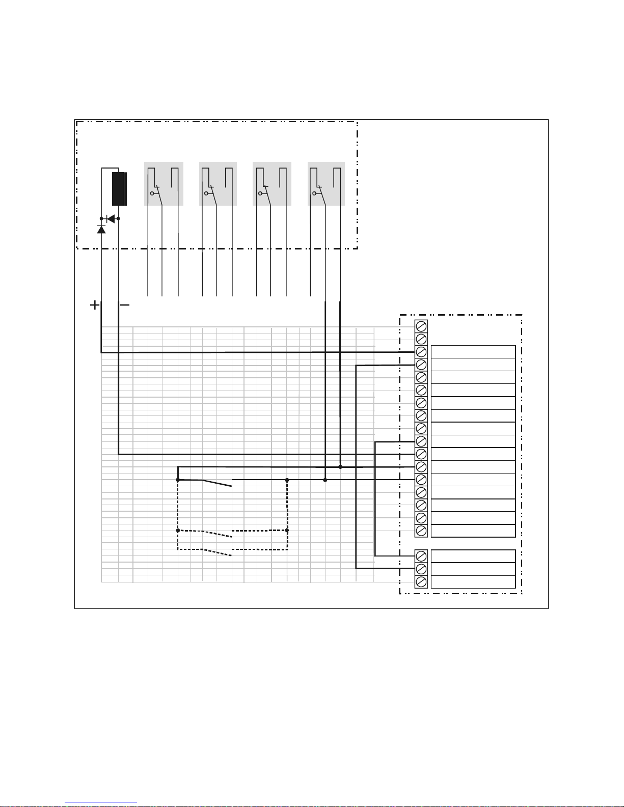
83
2.11 Special function II: Operation of the emergency exit control unit with the electrical
security lock 809
If both an emergency exit security system with control unit 720-30 or 720-32 and also an electrical security lock 809
are used at a door, it is advisable to wire the system in accordance with the above terminal diagram.
The electrical security lock is triggered via the
relay output "unlocked".
In the terminal diagram illustrated above, the n.c.
contact of the alarm relay is additionally looped into
the triggering conductor, meaning that in case of a
hazard unlocking process, the emergency exit
security system in turn triggers the temporary release
input of the emergency exit control unit.
The profile cylinder contact of the electrical safety
lock in turn triggers the temporary release input of the
emergency exit control unit.
or
720-30
720-32
D0019203A0001000
L 1
1819252627
284243
Electrical security lock 809
Fail locked version for 24 V VDC
Bolt switch
contact
S 1
External
handle contact
S 2
Internal handle
contact
S 3
Profile
cylinder contact
S 4
red
blue
yellow
pink
violet
brown
grey
white
grey-pink
black
brown-green
white-green
red-blue
Release key
e.g. of
access cont r ol system
L1=Coil:
Note polarity and nominal voltage
S1=Bolt switching contact
(drawn: bolt thrown)
S2=Limit switch door outside handle
switches only when the outside handle is actuated
S3=Limit switch door inside handle
switches only when the inside handle is actuat ed
S4=Prof il e cylinder contact
switches when actuating the profile cylinder
The contact which triggers the coil must be
connecte d in the fail locked versio n as a
make contact (normally open contact) and in
the fail unlocked version as a brea k contact
(normally closed contact).
Note
All contact positions are drawn unactuated.
When actuating the outside door handle ,
both door handle contacts ar e switched .
green
Page 84
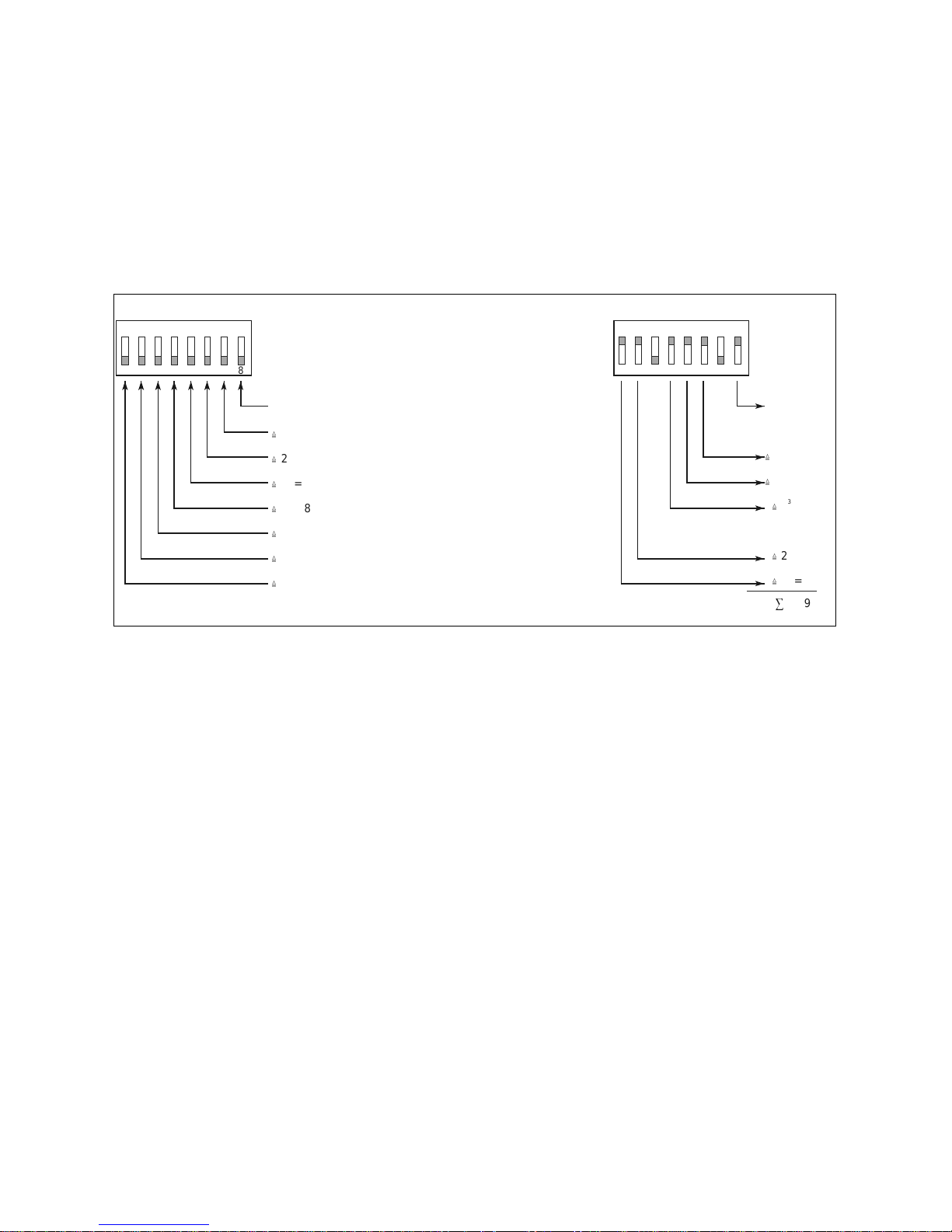
84
2.12 Special function III Operation of the control system at control panel 925 (bus
technology)
If the emergency exit control unit 720-30 or 720-32 is connected to a central c ontrol and m onitoring panel (bus
control panel ) 925, the switching and display functions at the door / at the terminal are largely the same.
Setting the bus address ( S 6 )
When operated at the bus control panel 925, each control unit must be assigned its own address which must be set
both at the DIP switch S6 of the control unit itself and also at the relevant door unit of the central panel.
Connecting the door control bus
The two-core bus line of the door control bus is connected to terminals A and B of the e mergency exit control dev ice.
Note! Do not confuse cables A and B!
For all other information relating to the installation, functional characteristics and commissioning please
refer to the "Operating and installation instructions for the bus control panel model 925".
Example:
Address no. = 59
Bus mode on/off
Bus mode on
ON ON
D0019203G0000600
¼
2 = 64
6
¼
2 = 32
5
¼
2 = 32
5
¼
2 = 16
4
¼
2 = 16
4
¼
2 = 8
3
¼
2 = 8
3
¼
2 = 4
2
¼
2 = 2
1
¼
2 = 2
1
¼
2 = 1
0
¼
2 = 1
0
3
= 59
12345678 12345678
Page 85

85
2.13 Specifications
Power supply 230 V +6%, -10%, 50 - 60 Hz
Maximum current consumption with rated voltage 0.3 A
Input voltage range with external power supply 24 V DC stabilized +15%, -10%
(safety extra-low voltage)
Intrinsic current consumption of the control system 150 mA
Current consumption of the safety relay circuit in 720-32 110 mA
Rated operating voltage 24 V DC
Maximum admissible overall current consumption of all external consumers appr. 1.1 A
Emergency power supply / battery capacity 24 V DC, 2Ah
Bridging time at rated load: appr. 15 mins.
Protective measures according to VDE 0100: Safety class I
Protection rating to DIN EN 60529 2000-09 IP 20
Operating temperature range 0°C to +40°C
Storage temperature range -20°C to +60°C
Dimensions WxHxD mm 300 x 186 x 125
Colour RAL 9002 grey-white
Weight (excluding batteries)
720-30: 5.28 kg
720-32: 5.52 kg
Weight of batteries (2 batteries 18002) 1.92 kg
Page 86

86
3 Commissioning, maintenance, recurr ing tests
The installation and operation of electrical locking systems for doors in escape routes are subject to
building supervisory regulations. Adherence to these regulations must be ensured by both the installer
and the operator.
3.1 Commissioning and recurring tests
Prior to initial commissioning of an electrical emergency exit locking system, correct installation of all elements
and their electrical connection must be checked. Particular care must be applied here to the elements for
releasing the locking system in case of danger.
As a rule, the correct mounting and function of the electrical emergency exit locking system must be approved
by an expert.
In addition, doors in escape routes which are fitted with electrical locks must be tested at least once a year by an
expert. The expert is required to issue a certificate confirming repeated testing, which the user must present to
the building supervisory authorities on request.
Note!
The instructions provided above relate to standard specifications. As the application of escape route
locking systems is regulated on the Federal State level, the relevant State Government building
legislation and test stipulations for technical equipment must be obse rved.
3.2 Maintenance
The devices described here do not require maintenance. Should faults occur during operation or in one of the
prescribed tests which are not caused by faulty installation or mounting, the relevant device must be
decommissioned immediately and sent to the manufacturer for checking.
Freedom from maintenance does not exonerate the user from the obligation to perform regular tests of the
emergency exit locking system.
Page 87

87
4 Checklist for testing prior to initial commissioning
Components
• All components comply with the EltVTR
– Integrated locking element ............................................................................................................... ❍
– Control system ..................................................................................................................................... ❍
– Operating element ............................................................................................................................... ❍
• Installation and operating instructions available ...................................................................................... ❍
• Form sheet for testing the emergency exit locking system prior to initial commissioning is available ❍
In the event of an external power supply of the locking system or parts of it:
• Compliance with energy supply EN 60 950 (CE symbol available)? ............................................ ❍
Installation
• The clear pass-through height of the door is not restricted to a value under 200 cm by the locking
element ................................................................................................................................. ❍
• Positioning of the emergency button corresponds to the stipulations of State
building legislation and the directives relating to electrical locking systems
for doors in escape routes. ................................................................... ❍
• The informative sign "EMERGENCY BUTTON" is available and correctlymounted. ....................... ❍
When mounting the locking system on a smoke / fire door:
• The position and mounting method used for the locking element complies with the stipulations
provided in the door manufacturer's proof of suitability. ....................................................................... ❍
Functional characteristics
➪ Activate the locking system.
➪ Check whether the red display is alight at the control element.
➪ Check (manually) whether the door is securely locked.
➪ Actuate the emergency button in the terminal / control panel (with indirect release)
• The door is released without delay................................................................................. ............. ❍
• The door can be opened without exerting considerable force........................................ ............. ❍
• Yellow and green LED light up at the terminal............................................................................. ❍
• The integrated acoustic alarm transmitter has responded........................................................... ❍
➪ Reset the alarm.
➪ Activate the locking system.
➪ Check whether the red display is alight at the operating element.
➪ Check (manually) whether the door is securely locked.
➪ Switch the system to continuous unlocking.
• The door is unlocked....................................................................................................... .............. ❍
➪ Actuate the emergency button in the terminal / panel (in case of indirect release)
• Yellow and green LED light up at the terminal............................................................................. ❍
• The integrated acoustic alarm transmitter has responded........................................................... ❍
If a danger signalling system (e.g. fire alarm system) is connected:
➪ Reset the alarm.
➪ Activate the locking system.
➪ Check whether the red display is alight at the operating element.
➪ Check (manually) whether the door is securely locked.
➪ Open the closed current loop of the danger signalling system.
• The door is released without delay................................................................................. ............. ❍
• The door can be opened without exerting considerable force........................................ ............. ❍
• Yellow and green LED light up at the terminal............................................................................. ❍
• The integrated acoustic alarm transmitter has responded........................................................... ❍
D0019203G0000600
Page 88

eff-eff Fritz Fuss GmbH & Co
Kommanditgesellschaft auf Aktien
Bildstockstraße 20
72458 Albstadt-Ebingen
Deutschland
Tel.: (07431) 123-0 http/www.effeff.com
fax (07431) 123-240/303
An ASSA ABLOY Group company
ASSA ABLOY
 Loading...