

Sicherheit und Präzision
Mini - Türcodegeräte
Mini Door Code Units
Bedienungsanleitung
Operating Instruction
421-40-10
421-41
421-42-10
421-43
D00157
05
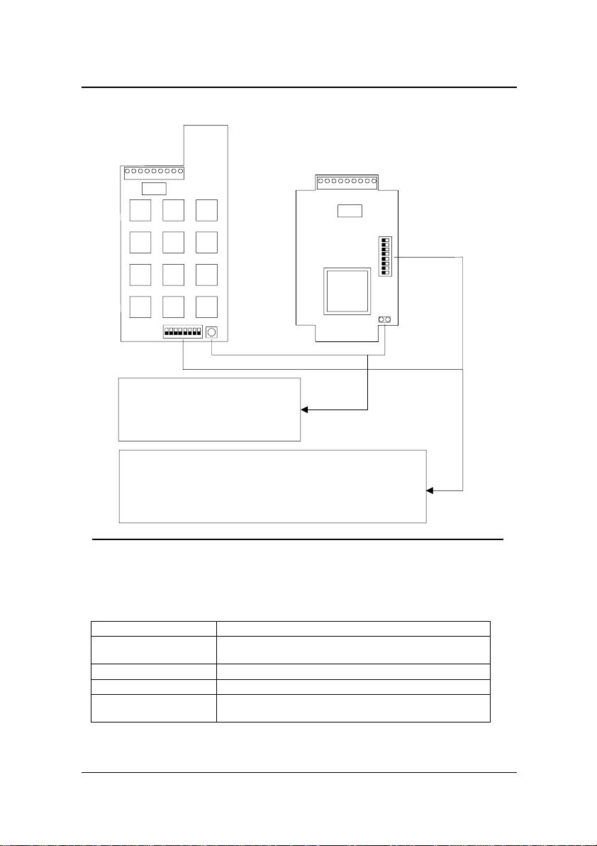
Leiterplattenansicht
Modell
421-40-10
421-42-10
123456789
ON
12345678
Taster bzw. Kontaktstifte zum durch-
führen eines "Code-Resets" . Der CodeReset wird durch Betätigen des Tasters
bzw. durch kurzzeitiges Überbrücken
der Kontaktstifte ausgelöst.
DIP-Schalterblock zur A uswah l de r B etriebsart sowie zur Ein st el l u ng
der Teilnehmeradresse in der Betriebsart Busteilnehm er.
Einzelgerät --> DIP-Schalter 8 in Stellung OFF
Busteilnehmer --> DIP-Schalter 8 in Stellung ON
Teilnehmeradresse --> Einzustellen mit den DIP-Schalter 1-7
D00157-G0000100
Modell
421-41
421-43
123456789
ON
12345678
JP 2
Technische Daten
Betriebsnennspannung 12 V DC
Eingangsspannungsbereich 8 - 20 V DC 50% Restwelligkeit
Betriebsnennspannung 12 V DC; +/-15%
Stromaufnahme des Gerätes 15 mA typisch bei Nennspannung
Nennstromaufnahme 15 mA (typ.)
Stromaufnahme des Gerätes
bei aktivem Relais 50 mA bei Nennspannung
Netzteilempfehlung effeff Bestell-Nr.: 1001-12-1
Kontaktbelastbarkeit max.1 A 24V DC ohmsche oder
Kontaktbelastbarkeit 24 V DC/1 A
induktive Last
Betriebstemperaturbereich 421-40/421-42-10: 0 °C bis +40 °C
50 mA (Relais angezogen)
421-41/421-43: -15 °C bis +40 °C
0
Betriebstemperatur Modelle 421-40/42-10 0
C - 400 C IP 30
2

Beschreibung
Das Mini-Türcodegerät bietet die
Möglichkeit, mit geringem Aufwand eine Zutrittskontrolle für zu
sichernde Bereiche aufzubauen.
Die Mini-Türcodegeräte können
als Einzelgeräte oder in Verbindung mit der effeff-Bus-
zentrale 900-10 als Busteilnehmer betrieben werden. Wird das
Mini-Türcodegerät als Einzelge-
rät verwendet, erfolgt die Bedienung sowie die Programmierung der Codes am MiniTürcodegerät. Bei der Verwendung als Busteilnehmer, erfolgt
die Programmierung ausschließ-
lich durch die Buszentrale.
Installation
Alle Anschlußarbeiten am Gerät
und Verriegelungselement müs-
sen gemäß Anschl ußplan durchgeführt werden. Die Stromversorgung für das Mini-Türcode-
gerät und das Verriegelungselement muß durch ein Gleichrichtergerät mit einer Ausgangsspannung von 12 VDC oder
durch die Buszentrale erfolgen.
Für die Installation sollten nur
abgeschirmte Leitungen mit einem geeigneten Leitungsquerschnitt verwendet werden.
Das Gerät muß an dem dafür
vorgesehenen Erdungsbolzen
geerdet und die Leitungsschirme
daran angeschlossen werden.
Störungen
Die Mini-Türcodegeräte sind gegen externe Störeinflüsse ge-
schützt. Um die Betriebssicherheit noch weiter zu erhöhen,
sollte das Gerät nicht extremen
Störfeldern ausgesetzt werden.
Sollte das Gerät infolge starker
Störungen dennoch nicht mehr
funktionieren, so ist dieses für
ca. 30 Sekunden von der
Versorgungsspannung zu trennen und anschließend wieder
einzuschalten.
Verriegelungsteile
Das Mini-Türcodegerät stellt einen potentialfreien Relaiskontakt
zur Ansteuerung eines Verbrauchers zu Verfügung. Für den
Standartbetrieb sind folgende
Verriegelungselemente vorgesehen.
Arbeitstromöffner
1405 und 1705 100% ED
Nennspannung 12 V(Spannungsbereich 11 - 13 V-)
Stromaufnahme: 1405 -> 200mA
1705 -> 230mA
Ruhestromöffner
3405 und 3705 100% ED
Nennspannung 12 V(Spannungsbereich 11 - 13 V-)
Stromaufnahme: 3405 -> 200mA
3705 -> 230mA
Diese Türöffnertypen sind mit
Freilaufdioden ausgestattet, die
Stör- und Abschaltspitzen kurzschließen. Werden andere Verbraucher als die oben aufgeführten angesteuert, sind diese
ebenfalls durch eine Freilaufdiode bzw. durch andere geeignete Maßnahmen zu entstören.
3
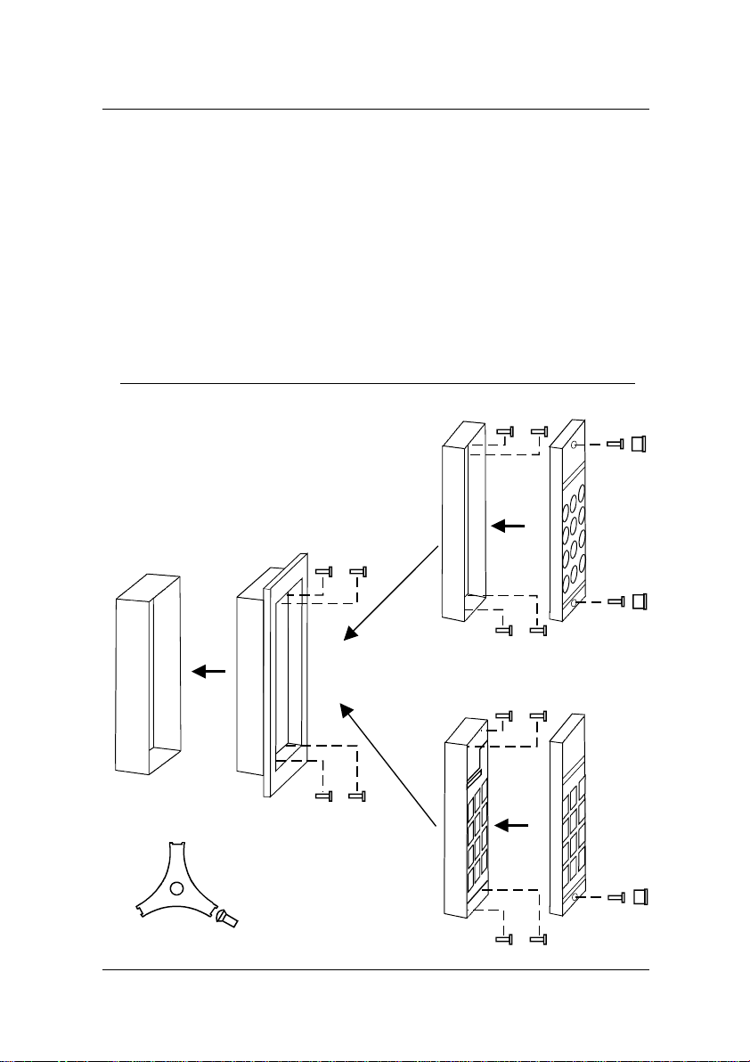
Montage
Bei Aufputzgeräten muß zuerst
der Gehäuseboden an einer geeigneten Stelle, vorzugsweise
neben dem Türrahmen, befestigt
werden. Wird die Unterputzausführung verwendet, so ist zunächst die Kunststoff-uP-Dose in
der Wand zu befestigen und
einzuputzen sowie die Zuleitungen durch die Kabeldurchführ-
ungen zu führen. Anschließend
ist der Blendrahmen und der
Montageset 41412-1:
Bestehend aus Einputzdose und Blendrahmen.
Wird bei den Unterputzgeräten 421-42-10
und 421-43 mitgeliefert.
Geräteboden mit der KunststoffuP-Dose zu verschrauben.
Beachten Sie, daß bei der Montage keine Leitungen oder Rohre
in der Wand beschädigt werden.
Außerdem ist darauf zu achten,
daß das Gehäuse sowie die Befestigungsschrauben keine Verbindung zu leitenden Teilen in
der Baukonstruktion haben, um
Störeinflüsse zu vermeiden.
Modelle 421-41/43
D00157-G0000200
4
Modelle 421-40/42-10
Freigabekontakt
Wird das Mini-Türcodegerät als
Einzelgerät betrieben, kann an
den Klemmen 6 und 7 ein Kontakt angeschlossen werden, mit
dem die Tür für die Freigabezeit
(Taster) bzw. für die Dauer der
Ansteuerung (Schalter) entriegelt
werden kann.
Inbetriebnahme
als Einzelgerät
Nachdem alle Montage- und Anschlußarbeiten durchgeführt wurden, kann das Gerät in Betrieb
genommen werden. Gehen Sie
dabei wie folgt vor:
Schalten Sie die Stromversorgung für das Gerät ein.
Führen Sie einen Code-Reset
durch, um alle eventuell programmierten Codes zu löschen
und den Änderungscode auf die
Werkseinstellung 0 0 0 0 einzustellen.
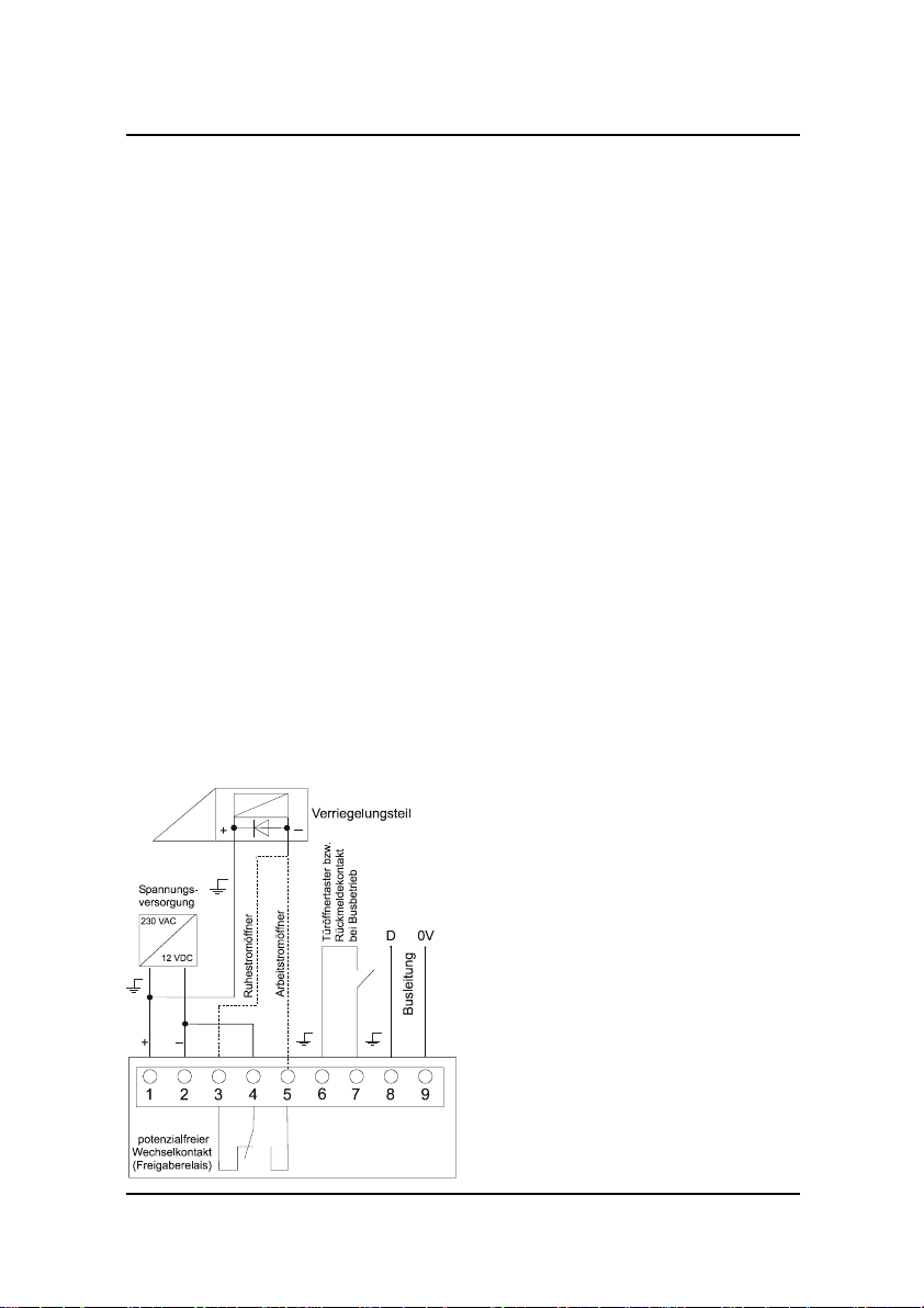
Anschlußplan
Verriegelungsteil
+
Spannungs-
versorgung
230 VAC
12 VDC
_
+
1234
potentialfreier
Wechselkontakt
(Freigaberelais)
D00157-A0000100
_
D0V
Rückmeldekontakt
bei Busbetrieb
Türöffnertaster bzw.
Arbeitstromöffner
Ruhestromöffner
6
5
Busleitung
789
Überprüfen Sie die Funktion des
Gerätes und des angeschlossenen Verriegelungsteils durch
die Eingabe des Änderungs-
codes 0 0 0 0.
Verwendung am TS-Bus
Das Mini-Türcodegerät kann als
Busteilnehmer am TS-Bus betrieben werden. Dazu muß der
DIP-Schalter 8 in Stellung ON
gebracht und mit den DIPSchaltern 1-7 die Teilnehmer-
adresse des Gerätes eingestellt
werden. Zusätzlich muß an den
Klemmen 8 und 9 die Busleitung
zur Zentrale angeschlossen
werden.
Beim Anschluß der Busleitung ist
unbedingt auf die richtige Polarität zu achten.
Bei der Verwendung als Busteilnehmer muß an den Klemmen 6 und 7 ein Rückmeldekon-
takt angeschlossen werden. Mit
diesem Kontakt wird überwacht,
ob die Tür geschlossen ist (Tür
geschlossen - Kontakt geschlossen). Steht kein Kontakt zur
Verfügung, müssen die Klemmen 6 und 7 verbunden werden.
Zusätzliche Hinweise zur Installation und zum Betrieb am TSBus sowie zur Einstellung der
Teilnehmeradresse entnehmen
Sie bitte der Bedienungsanleitung, die der Buszentrale beiliegt.
5

Programmierung
Änderungscode:
Der Änderungscode kann zur
Freigabe der Tür genutzt werden, und ist erforderlich, um die
Benutzercodes zu programmieren. Programmiert wird der Änderungscode, indem der momentan gültige Änderungscode
eingegeben und innerhalb von
3 Sekunden der Programmiermodus durch Betätigen der
Taste "-" aktiviert wird.
Anschließend kann der neue
4-stellige Code eingegeben werden. Beendet wird der Programmiervorgang durch Betätigen
der Taste "+". Für den gesamten Programmiervorgang stehen
maximal 13 Sekunden zur Verfügung. Ist die Programmierung nicht innerhalb dieser Zeit
abgeschlossen, wird der Programmiervorgang abgebrochen
und der bisher gültige Code
bleibt erhalten.
Benutzercode:
Es stehen drei 4-stellige Benutzercodes zur Verfügung, die mit
dem Änderungscode programmiert werden können. Programmiert werden die Benutzercodes, indem zunächst der Änderungscode eingegeben wird,
gefolgt von der Taste "-". Anschließend ist der Index des Benutzercodes einzugeben z.B. "1"
für den ersten bzw. "2" oder "3"
für die weiteren Benutzercodes, wiederum gefolgt von der
Taste "-".
Danach kann der 4-stellige Benutzercode eingegeben und die
Programmierung durch Betätigen
der Taste "+" abgeschlossen
werden. Für den gesamten Programmiervorgang stehen wieder
maximal 13 Sekunden zur
Verfügung.
Freigabezeit
Die Freigabezeit nach Eingabe
eines gültigen Codes beträgt
3 Sekunden.
Dauerentriegelung
Mit der Dauerentriegelungsfunktion besteht die Möglichkeit, das
Verriegelungselement unabhän-
gig von der Freigabezeit zu entriegeln. Es kann jedoch nur der
Benutzercode 1 für diese Funktion verwendet werden. Dazu ist
der Code einzugeben, wobei die
letzte Ziffer um zwei erhöht werden muß, ohne Übertrag auf die
nächste Stelle. Beispiel: Der
Benutzercode 1 sei "1234", so
muß für die Aktivierung der
Dauerentriegelung die Ziffernfolge "1236" eingegeben werden.
Zurückgesetzt wird die Dauerentriegelung durch Eingabe des
Benutzercodes 1 "1234".
Falschcodeauswertung
Damit ein gültiger Code nicht
durch probieren herausgefunden
werden kann, wird die Tastatur
gesperrt, wenn nicht spätestens
mit der achten Tastenbetätigung
ein gültiger Code vollständig eingegeben ist. Die Sperrung der
Eingabetastatur beträgt 30 Sekunden.
6

Programmierbeispiel
Löschen
durch Betätigen des Tasters oder
brücken der Kontaktstifte "
Programmierung eines neuen
Änderungscodes.
Eingabe des aktuell gültigen
Änderungscodes
aller programmierten Codes
Code-Reset
421-40/42-10 421-41/43
"
JP 2
0000
Programmiermodus
einleiten
Eingabe des neuen Änderungscodes
753
Programmiermodus
beenden
Benutzerco de- Index
Es stehen drei programmierbare Benutzercodes zur Verfügung, denen die
Indizes 1, 2 und 3 zugewiesen sind. Bei
der Programmierung der Benutzercodes ist der entsprechende Index
zwischen den beiden Betätigungen der
Taste "-" einzugeben.
+
753
0
0
Programmieren eines Benutzercodes
am Beispiel des "Benutzercodes 1".
Eingabe des Änderungscodes
753
Programmiermodus
einleiten
Index für "Benutzer-
code 1" eingeben
Verzweigung zur
Codeeingabe
Eingabe des gewünschten
"Benutzercodes 1".
1
214
Programmiermodus
beenden
Dauerentriegelung mit dem
programmierten "Benutzercode 1"
Aktuell gültiger Benutzercodes 1
+
0
3
1 2 3 4
Eingabe des Dauerentriegelungscodes
Zurücksetzen der Dauerentriegelung
durch Eingabe des "
1236
Benutzercodes 1
"
1 2 3
,
,
oder
1234
7

8

Operating Instructions
9

View printed circuit board
Model
421-40-10
421-42-10
123456789
ON
123
45678
Push button or co ntact p in for making a
"code reset". The code reset is
triggered by opera ting the push button
or by briefly bridging the contact pins.
DIP switch block for select ion of the operating mode and for setti ng
the address when operating in a Bus system.
Stand alone --> DIP-switch 8: position OFF
Bus operation --> DIP-switch 8: position ON
Bus address --> to be set via DIP-switches 1-7
D00157-G0000100
Model
421-41
421-43
123456789
ON
12345678
JP 2
Technical Data
Nominal operating voltage 12 V DC
Nominal operating voltage 12 V DC; +/-15%
Input voltage range 8 - 20 V DC 50% residual ripple
Nominal
Current consumption
Current consumption of the unit 15 mA typical at nominal voltage
Recommended
Current co nsumption of the unit
power supply
when relay is activated 50 mA at nominal voltage
Contact load capacity 24 V DC/1 A
Contact load capacity max.1 A 24V DC ohmic or
Operating
temperature range
inductiv load
Operating temperature Models 421-40/42-10 0
Models 421-41/43 -15
15 mA (typical)
50 mA (relay is activated)
effeff Order-Nr.: 1001-12-1
421-40/421-42-10: 0 °C bis +40 °C
421-41/421-43: -15 °C bis +40 °C
0
C - 400 C IP 30
0
C - 400 C IP 42
10

Description
The mini door code unit offers
the possibility to easily install an
access control system for areas
which have to be protected. Mini
door code units can be operated
as individual devices or as Bus
parties in connection with the
effeff Bus central unit 900-10.
If the mini door code unit is used
as an individual device,
operation and programming of
the codes is carried out at the
mini door code unit itself. If it is
used as a party to the Bus,
programming can only be
effected via the Bus central unit.
Installation
All connections at the unit and
the locking element must be
carried out in accordance with
the connection diagram. Current
supply for the mini door code
unit and the locking element
must be provided by means of a
rectifier unit with an output
voltage of 12 V DC or by means
of the Bus central unit.
Regarding the installation, only
shielded wires with suitable
cross section shall be used.
The unit must be earthed at the
earthing bolts provided and the
wire shields must be connected
to it.
Interferences
The mini door code units are
protected against external
interferences. In order to further
increase the operational
reliability the unit shall not be
subjected to extreme interference fields. In case considerable interferences cause the
failure of the unit, it must be
disconnected from the supply
voltage for approx. 30 seconds
and then be switched on again.
Locking parts
The mini door code unit provides
a potential free change-over
relay contact for triggering of a
consumer. Following locking
elements are intended to be
used for standard operation.
Fail-locked strikes
1405 and 1705
100 % continuous duty
Nominal voltage 12 V DC
(Voltage range 11 - 13 V DC)
Current consumption:
1405 -> 200mA 1705 -> 230mA
Fail-unlocked strikes
3405 und 3705
100% continuous duty
Nominal voltage 12 V DC
(Voltage range 11 - 13 V DC)
Current consumption:
3405 -> 200mA 3705 -> 230mA
These strike models are
equipped with recovery diodes
which short-out interference
peaks and cutoff spikes. In case
consumers not mentioned above
shall be triggered, a recovery
diode must be provided or other
suitable measures have to be
taken to guarantee interference
protection.
11

Mounting
With regard to surface mounting
version, first of all the bottom of
the housing must be fixed in a
suitable position, preferably next
to the door frame. In case a flush
mounting version is used, the
corresponding plastic housing
must be fixed in the wall first.
Then the plaster work has to be
done and the supply lines have
to passed through the
cable
bushings. Afterwards the frame
Mounting set 41412-1:
Consists of housing for
flush mounting and
frame. Is supplied with
flush mounting units
421-42-10 and 421-43.
and the bottom of the unit have to
be connected with the plastic
flush mounting housing by
screws. Please take care that no
leads or tubes inside the wall are
damaged when mounting the
unit. Furthermore it must be
ensured that there is no
connection between the housing
or the fixing screws and
conducting parts in the
construction of the building in
order to avoid interferences.
Modelle 421-41/43
D00157-G0000200
12
Modelle 421-40/42-10

Release contact
If the mini door code unit is used
as an individual device it is
possible to connect a contact to
terminals 6 and 7 by means of
Check the function of the unit
and of the connected locking part
by input of the modification code
"0 0 0 0".
which the door can be unlocked
during the release period (push
button) or during triggering
(switch)
Use at the TS-Bus
The mini door code unit can be
operated as a Bus party at the
TS-Bus. The DIP switch 8 must
Initial operation as an
individual device
After all mounting and installation
works have been carried out the
unit can be set into operation.
Please proceed as follows:
Switch on the power supply for
the unit.
Carry out a code reset in order to
delete any codes that might be
programmed and to set the
modification code to
the factory
setting "0 0 0 0".
Connection Diagram
Locking element
o
+
_
be in position ON and the Bus
address of the unit must be set
by means of the DIP switches
1-7. Additionally, the Bus wire to
the central must be connected to
the terminals 8 and 9.
When connecting the Bus it is
imperative to guarantee correct
polarity of the two wires.
In case the unit is used as a Bus
party, a monitoring contact must
be connected to the terminals
6 and 7. By means of this contact
it is possible to monitor if the
door is closed (door closed
contact closed). If no contact is
available, the terminals 6 and 7
must be connected.
Power supply
Potential-free
change over
contact relay
D00157-A0000100
For additional information
regarding the installation, the
Release button or
monitoring contact
for Bus operation
operation at the TS-Bus and the
setting of the Bus address please
Fail-locked strike
Fail-unlocked strike
see the operating instructions
Bus wire
attached to the Bus central
unit.
13

Programming
Master code:
The master code can be used
for releasing the door and is
required for programming the
user codes. For programming
the master code, the master
code which is valid at the
moment must be entered and
the programming mode must be
activated within 3 seconds by
operating the key "-". Afterwards
the new 4-digit code can be
entered. Programming is terminated by operating the key
"+". The complete programming
must be carried out within 13 seconds. In case programming is
not carried out within this period
of time, the process is
interrupted and stopped and the
previously valid code is
maintained.
User code:
Three 4-digit user codes are
available which can be programmed by the master code.
When programming the user
codes, first the master code
must be entered and then the
key "-" must be operated.
Afterwards the index of the user
code must be entered e. g. "1"
for the first one or "2" or "3" for
further user codes and the key
"-" must be operated
Then the 4-digit user code can
be entered and the programming
can be terminated by operating
the key "+".
again.
The complete programming must
also be carried out within 13 se-
conds maximum.
Release period:
The release period after entering
any valid code is 3 seconds.
Permanent unlocking:
The permanent unlocking
function offers the possibility to
unlock the locking element
regardless of the release period.
However only user code 1 can be
used for this function. The code
must be entered and the last
figure must be increased by 2
without carrying over any amount
to the next digit. Example: The
user code 1 is "1234". For
activating the permanent
unlocking mode the figures
"1236" must be entered. The
permanent unlocking mode is
reset by entering the user code
"1234".
Erroneous code evaluation:
In order to prevent that somebody
finds out a valid code by trial and
error the keypad is blocked if no
complete code has been entered
after maximum 8 key operations.
The keypad remains blocked for
a period of 30 seconds.
14

Programming example
Deleting of all programmed Codes by
operating the push button or bridging
the contact pins "code reset".
JP 2
421-40/42-10
Programming of a new master code.
Entering of the master code valid at the
moment
421-41/43
0000
Triggering of the
programming code
Entering of the new master code
753
Terminating of the
programming mode
User code index
The indexes 1, 2 and 3 are assigned to
the three programmable user codes that
are available. When programming the
user codes the corresponding index
must be entered after operating the
key "-" for the first time and before
operating the key "-" for the second
time.
+
0
7530
Programming of a user code
Example: "User code 1"
Entering of the master code
7530
Triggering of the
programming mode
Entering of index
for "user code 1"
Branching for entering
of the code
Entering of the desired "user code 1"
Terminating the
programming mode
Permanent unlocking with the
programmed "user code 1"
User code 1 which is valid at the
moment
1
3
214
+
1 2 3 4
Entering of the code for permanent
unlocking
1236
1 2 3
,
,
oder
Resetting of the permanent unlocking
mode by entering the
"user code 1".
1234
15

ASSA ABLOY
Sicherheitstechnik GmbH
Bildstockstraße 20
D-72458 Albstadt
Telefon +49 74 31/1 23-0
Telefax +49 74 31/1 23-240
info@assaabloy.de
www.assaabloy.de
An ASSA ABLOY Group brand
ASSA A BLOY
 Loading...