

Page 1
Rev. JG.013-02-04
EFFECTA PELLETS 222
INSTALLATION
MAINTENANCE
SERVICE
ASSEMBLY
Page 2

Effecta AB - Västra Rågdalsvägen 21 - 434 99 Kungsbacka - +46(0)300 - 22320 - info@effecta.se
2
We at Effecta would like to thank you for putting your trust in us when choosing your new boiler.
The ”Effecta 222” has been developed to give you maximum performance, comfort and quality.
In order to get the best results from your boiler, we suggest that you follow the recommendations
in this installation guide.
Checking your delivery
Check that the boiler has not been damaged during transportation. If the boiler has been
damaged, you must report this to the transportation company immediately.
Your safety
If you discover any faults or defects in our products, it is important that you report them as
quickly as possible to your installation engineer, so that the fault can be rectified. Make sure
that there are no flammable materials close to the boiler, to help prevent risk of fire. You must
use your own judgement when operating the pellet boiler. Remember that the hatches and some
surfaces can get hot. You must take caution to avoid being burnt.
The user
It is the user´s responsibility to operate the boiler according to our instructions. If you do not
operate and maintain your boiler correctly, the environmental impact of the boiler will be greater,
it´s efficiency will be reduced and the service life of some components will be shorter. If there
is anything that you are not sure about, please contact your installation engineer or Effecta for
advice.
Warranty
The warranty takes effect from the date on which the boiler is installed. The supplied installation
form must be completed and returned to Effecta. You can find the other guarantee terms on
(page 3).
▀
Scope of delivery
Please check all components delivered.
The standard delivery as follows:
- Effecta 222 boiler
- Cleaning handle with brush
- Rake with scraper
- Flue tube with draft stabiliser
- Turbulators, 6pcs.(mounted)
- Drain cock
- Shunt valve with return pex pipe
- Electrical heater 3+3+3 kW (mounted)
- Valve combination
▀
Introduction
Page 3
Effecta AB - Västra Rågdalsvägen 21 - 434 99 Kungsbacka - +46(0)300 - 22320 - info@effecta.se
3
▀
System data:
▀
Warranty
Installer:
Date:
Electrical installer:
Effecta products are guaranteed to be free of defects in materials and workmanship for two years
from the installation date. This applies to wear parts, such as seals, the main body of the boiler and
electrical components. This guarantee also covers original spare parts. Any faulty products will be
replaced or repaired at the discrimination of the retailer or Effecta. If a faulty product is detected,
Effecta is entitled to replace it with a new or reconditioned product of the same or a similar type.
Effecta is liable for the costs of any servicing or repairs. Effecta gives a 5 year guarantee on the
remaining components. See the attached guarantee document.
If you have a complaint, you must contact Effecta before starting any servicing work. You must
submit your complaint without delay. You must always state the type of product, the date of
purchase and the serial number.
Otherwise the heating and plumbing industry's current regulations apply in case of complaints.
Guarantee terms:
The guarantee is valid on condition that:
- The boiler and the heating system have been installed in accordance with the installation instructions
and in a professional manner.
- The location where the product is installed is suitable for the purpose.
The guarantee does not cover:
- The overall functioning of the heating system, costs incurred as a result of the heating system
being out of operation, or the cost of the temporary replacement of products.
- Damage or injury caused by negligence during the installation or by operating the boiler in a
way which conflicts with the installation and user instructions.
- Damage caused by abnormal wear, incorrect operation and maintenance.
- Damage caused by the boiler being positioned in an unsuitable location.
- Damage caused by vermin.
Page 4
Effecta AB - Västra Rågdalsvägen 21 - 434 99 Kungsbacka - +46(0)300 - 22320 - info@effecta.se
4
▀
Contents
Introduction 2
Check of the delivery 2
Your safety 2
The user 2
Warranty 2
Scope of delivery 2
Warranty 3
System data 3
Contents 4
In general 5
Dismantling and disposal 5
Pellets 5
Symbols 5
To the installer 6
Boiler room 6
Chimney 6
Set up 6
System components 7
Shunt valve 7
Valve combination 7
Overheating protection 7
Micro switch 7
Seal 7
Cleaning 7
Flue gas temperature 7
Control panel 8
Placement of the components 9
Service and cleaning 10
Automatic cleaning 11
Hot water 12
Valve combination 12
Shunt valve 12
Cleaning 13
Electrical connection 14
Electrical connection 15
Electrical connection 16
Technical data 17
Hydraulic scheme 18
Draft stabiliser 19
Trouble shooting 20
CE-Mark 21
Page 5
Effecta AB - Västra Rågdalsvägen 21 - 434 99 Kungsbacka - +46(0)300 - 22320 - info@effecta.se
5
▀
In general
The Boiler
Effecta 222 is a boiler which is to be fueled with wood pellets. No other kind of fuel is allowed to
be used. Not logs or oil.
Disassembly and disposal
It will be many years before your Effecta boiler is worn out, but it is important that you follow the
regulations in force at the time concerning disassembly and disposal of your boiler.
The fuel
The boiler should normally burn 6/8 mm pellets which come either in 16 kg sacks or are supplied
by bulk truck. If you have built a bulk storage, you should follow the current recommendations to
ensure that the quality of the pellets does not deteriorate. Never use pellets which do not meet
European pellet standards, as this may result in problems in operating the burner.
▀
Symbols in the manual
Information
This symbol is shown with info to the installer which can be important to know and understand.
Neglecting these informations can affect the performance of the product.
Dangerous electricity
This symbol means that extra caution should be taken. Otherwise serious personal injury
might occur. When maintaining the product where this symbol is present the power must be
disonnected. All electrical wiring must be done by a proffesional.
This product manual is a living document. You will always find the latest verion on our
webpage, www.effecta.se
▀
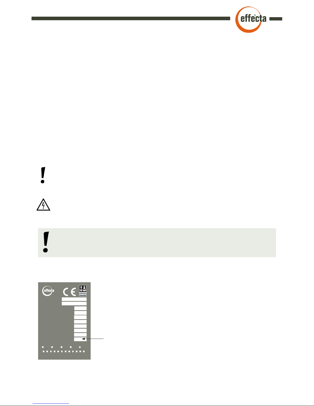
Type plate
2012 2012 2013 2014 2015
Tillverknings år. / Manufacturing year
Tillverkare / Manufactory
Hersteller / Fabricants
Modell / Model
Typ / Modéle
Max drifttemp. / Max temp. (C)
Max. Betriebstemp. / Temp d’opération max
Effekt / Heat output
Heizleistung /Puissance nominale (kW)
Elinstallation / Electrical supply
Strom / Branchement électrique (VAC)
El-patron / Electrical heater (kW)
El-Patrone / El-cartouche
Vattenvolym / Water volume
Wasserinhalt / Contenance d`eau (litre)
Tillverknings nr / Manufacturing number
Herstell Nr / Numéro de fabrication
Effecta Energy Solutions AB
Effecta 222
100
20
230/380~50Hz
2 /6 / 9
205
Effecta AB - Sweden - Kungsbacka - www.effecta.se
Max drifttryck / Max pressure
Max Betriebsdruck / Pression maximum (bar)
1,5
Tillverknings månad / Manufacturing month
1 2 3 4 5 6 7 8 9 10 11 12
Godkänd enl. / Approved by
Zugelassen nach / Approuvé á
EN-303-5
The type is placed on the top of the boiler. Here you can see
production number, month and year.
Page 6
Effecta AB - Västra Rågdalsvägen 21 - 434 99 Kungsbacka - +46(0)300 - 22320 - info@effecta.se
6
▀
To the installer
It is time to install the Effecta 222 pellet boiler. Please follow the examples we provide for a safe
installation. After installation, be sure to instruct the customer on how the heating system and the
boiler work, in order to avoid unnecessary complications in the future.
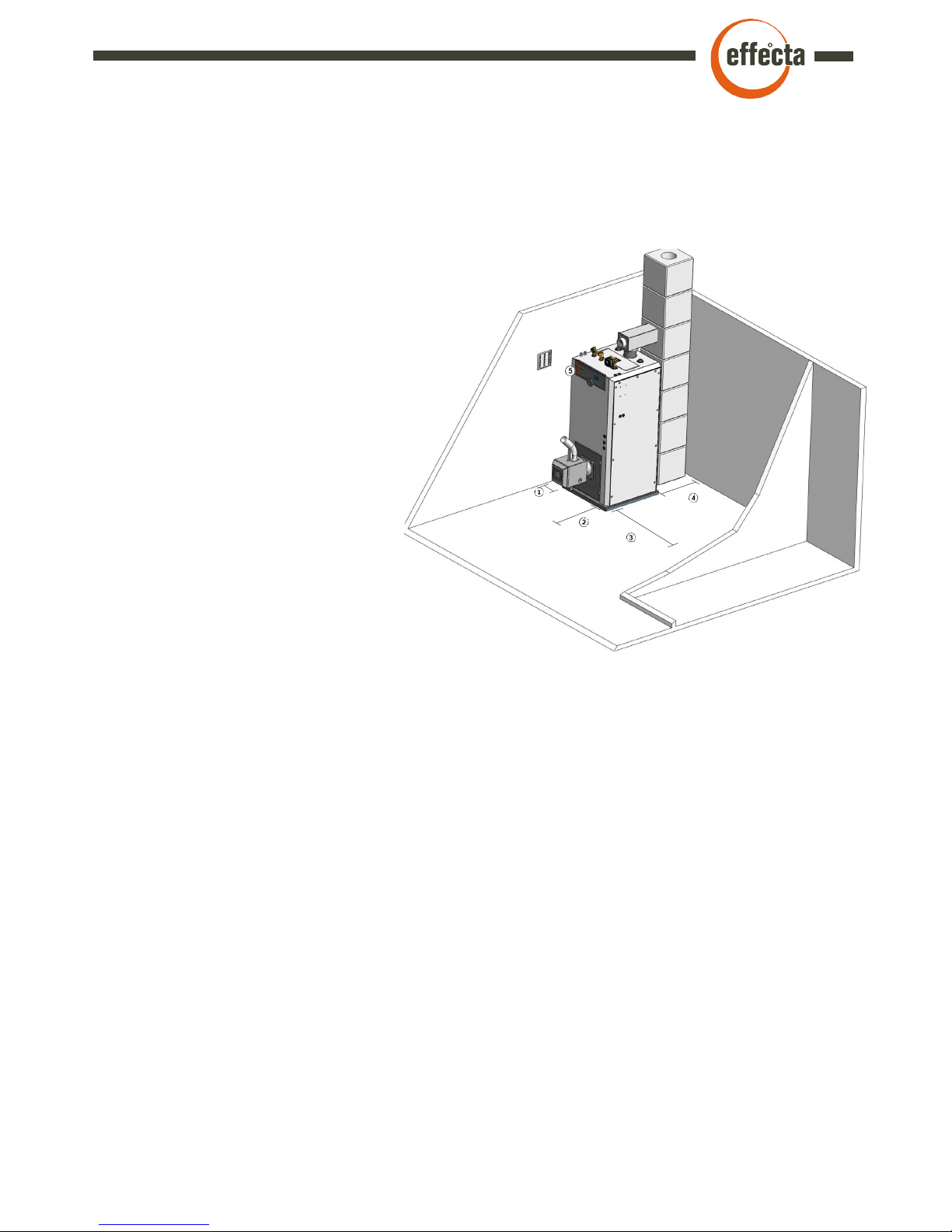
Set up
The boiler is positioned so that the surface
temperature of flammable building material does
not exceed 80°C. The boiler should be positioned
at least 15 cm (1) from the wall. The distance
from the flue tube on the boiler to a flammable
wall with ignition protective covering must
be at least 30 cm (4). In order to clean the
boiler, a minimum clear space of 1 metre
(2) is required in front of the boiler and
on the side at the convection section
and at any inspection panel in the
chimney. A passage with a minimum
width of 0.5 (3) m is required along
one of the long sides of the boiler.
The pellet hopper isn`t allowed to
stand closer than 120 cm from
the boiler.
The boiler room
The boiler must be installed in a boiler room or
boiler house. The ceilings and walls must be fitted with
ignition protective covering and the floor must be made of noncombustible material. Minimum ceiling height at the boiler is 2 metres. The boiler room or boiler
house must be equipped with a fresh air intake with the minimum dimensions 150 x 150 (5.) mm
or with a sufficiently large free sectional area to avoid low pressure in the boiler room. It must be
impossible to close the air intake.
Chimney
The chimney should have a diameter of at least 120 mm. If your chimney is smaller, Effecta should be
consulted before installation. The draught in the chimney should be about 15 pa at low temperatures.
It is important that the chimney is tested and approved by a certified chimney sweep before a new
boiler is installed. If the chimney has a strong draught, a draught controller may need to be installed
for good boiler operation. If you have a tall chimney and an outgoing flue gas temperature below
170°C, there is a risk of condensation in the chimney, which can damage the chimney in the long
term. A suitable temperature is 70-80°C one metre down into the chimney. Ask your local chimney
sweep for help to measure the temperature. If the chimney is tall and has a large area, a draught that
is too strong may mean high levels of flue gas and over ignition in the ash compartment. If this is the
case, a draft stabiliser must be installed.
Page 7

Effecta AB - Västra Rågdalsvägen 21 - 434 99 Kungsbacka - +46(0)300 - 22320 - info@effecta.se
7
▀
System components
The shunt valve
The shunt valve controls the heat supply from the boiler to the radiator circuit.
The room temperature can be adjusted on a scale on the thermostat. An automatic system
will significantly reduce fuel usage and provide a more comfortable environment.
The valve combination
The mixing valve is used to ensure that the temperature of the hot water in your shower
and elsewhere in the house is comfortable. Set the system to the temperature you want by
turning the thermostat between +/-.
Overheating protection
The overheating protection is a safety device if the burners thermostat should malfunction.
If the boiler has been overheated you must reset the overheating protection manually, by
pressing the red button (press hard) on the control panel.
Micro switch
The micro switch stops the auger alt. the whole burner, (depending on installed burner) if the
ash door is open. It´s important that this functions works and is checked regurlarly.
The sealings
The seals on the hatches must be checked every year. If the hatches do not seal properly,
the efficiency and the combustion process of the boiler will deteriorate.
Control panel
The functions of the control panel should be checked every year to avoid downtime of the
boiler or burner.
Cleaning
Cleaning is done from the top of the boiler. Take away the top cover and unscrew the nuts
on the lid over the tubes. Remove the turbulators and clean the tubes with the cleaning
handle with brush. Then open the ash compartment door and clean the burner and the ash
compartment. If your boiler is equipped with automatic cleaning of tubes, read the
instructions on pg. 11.
Flue gas temperature
The temperature that leaves the boiler should be in the range of 160-230°C if there is
condensation in the chimney the temperature must be higher.
To achieve a higher flue gas temperature you can cut the turbulators 5cm.
Page 8

Effecta AB - Västra Rågdalsvägen 21 - 434 99 Kungsbacka - +46(0)300 - 22320 - info@effecta.se
8
1 Overheating protection Cuts power when the temperature exceeds 95ºC
2 Display Status of the heating system
2 Keypad Maneuvering in the menus
▀
Control panel
Page 9

Effecta AB - Västra Rågdalsvägen 21 - 434 99 Kungsbacka - +46(0)300 - 22320 - info@effecta.se
9
Front Top Back
1 Adjustable feet 1 Smoke connection 1 Drain
2 Soot door 2 Cable gland 2 Return hotwater
3 Microswitch (inside the door) 3 Valve combination 3 Cable gland
4 Handle 4 Shuntvalve
5 Hole for burner 5 Lid
6 Control panel 6 Expansion / hotwater
7 Power for burner* 7 Hole for measuring instrument
8 Flame sensor*
9 Power for auger*
▀
Placement of the components
*Only with Effecta Supra/Aero.
Page 10

Effecta AB - Västra Rågdalsvägen 21 - 434 99 Kungsbacka - +46(0)300 - 22320 - info@effecta.se
10
▀
Service and cleaning
Cut the power to the boiler before starting the service. We recommend a good service/
cleaning of the burner and boiler 2-3 times a year. Do as follows for best result and
minimizing the chances for downtime.
Cleaning the ash compartment
Cleaning the ash compartment is done through the ash door on the front. The easiest way is to
use some type of ash cleaner. If you do not have access to a an ash cleaner, remove the ash
with a scrape and keep it in a fireproof bin. Remember that ashes can contain hot particles for
a long time and may not be stored near flammable materials.
Cleaning the burner
Clean the burner according to the manufacturer´s instructions. If you have an Effecta Supra
read more about service and cleaning in the burner manual.
Cleaning of the convection part
Clean the tubes with the supplied brush, follow instructions how to remove the turbulators on
pg 13. It´s important for the boilers efficiency that these are cleaned thoroughly at the service.
Cleaning of sootbox and fluetube
Soot box, which is placed above the tubes must be emptied of ash, if the soot box is full, the
flue gas has no place to escape out through the chimney and you will receive a disruption. Also
clean the flue tube that goes to the chimney, when it is not certain that the chimney sweep do it.
Sweeping range
1. Ash compartment, after about 3 tons of pellet consumption
2. Burner, according to the manufacturer´s instructions
3. Convection part, after about 3 tons of pellet consumption
3. Without automatic cleaning every other week in winter
4. Ashbox when necessary
5. Sootbox after about 3 tons of pellet consumption
6. Flue tube after about 3 tons of pellet consumption
Page 11

Effecta AB - Västra Rågdalsvägen 21 - 434 99 Kungsbacka - +46(0)300 - 22320 - info@effecta.se
11
Magnet motor
The magnet motor is mounted on the right side of
the soot hatch on the top of the boiler. The magnet
motor flips the turbulators up and down to keep the
tubes clean.
1 Magnet motor
2 Lyfting shaft
3 Flipper
4 Suspension
5 Turbulator
Turbulators
The turbulators in the tube helps reducing the flue
gas temperature and also cleaning the tubes when
pulled up and down.
▀
Automatic cleaning system (optional)
Function and service
Cut the power to the boiler before servicing. The magnet motor is mounted on the boiler to keep
the convective part clean. It is controlled from the menu ”Cleaning” on the control panel. It can
be set to work/not work in different times during the day.
Suspensions
On every suspension there are three turbulators
that is removed when you clean the tubes with a
brush.
Lyfting shaft
The shaft is pulled up by the magnet making the
turbulators also being pulled up.
Flipper
Flips when the magnet motor activates.
There must be no embers/glow in the burner when you start the cleaning
Page 12

Effecta AB - Västra Rågdalsvägen 21 - 434 99 Kungsbacka - +46(0)300 - 22320 - info@effecta.se
12
1 Temperature control 6 Flow control valve
2 Hot water out 7 Mixing valve
3 Cold water 8 Vent pipe
4 Hot water 9 Safety valve
5 Cold water in 10 Overflow pipe
▀
Hot water
Hot water is produced in a copper coil. There are flanges on the
outside on the coil for best heat absorption. The cold incoming
water is mixed with the heated water from the coil in the mixing
valve (1). The mixing valve includes a thermostat where you set
the temperature on the outgoing water. If you don’t run the boiler
with pellets there also is a possibility to heat the hot water with the
electrical heater which should be set to 70°C for good hot water
comfort. If the operating temperature of the burner or electrical
heater is too low, the coil will not deliver the quantity of hot water
as desired for larger amounts.
When hot water is prepared in a coil, legionella bacteria cannot
occur.
▀
Valve combination
The valve combination is there so the hot water temperature doesn’t get to scalding temperature. In order to increase the temperature
turn (1) against +. You may also need to tune
the flow valve (6) to reduce the flow through
the coil. There is a safety valve (9) that releases the water out of overflow tube (10) if the
pressure in the hot water circuit is too high.
Note that overflow pipe should always have
drainage to a floor drain.
The shunt valve is not mounted from factory. This because you
should be able to choose side to be the flow and return to the
boiler. The supplied plastic pipe (1) is placed on the side for
the return of the radiator circuit. Then screw the pipe in the
shunt valve, do not forget the gasket. Note that you may need
to pull the two m8 bolts tightly against gasket for it to be tight.
Also note that the electrical connection (open / close) will be
different depending on which side the return pipe is placed.
▀
Shunt valve
Page 13

Effecta AB - Västra Rågdalsvägen 21 - 434 99 Kungsbacka - +46(0)300 - 22320 - info@effecta.se
13
After about 3 tons the tubes should be cleaned manually with the brush, for the boiler to maintain a high
efficiency. Follow the instructions below.
Start by removing the lid on the top of the boiler
(1). Then loosen the two nuts(2) and remove the
hatch(3). Lift up the two suspensions with turbulators(4).
Clean the tubes with the brush
The ash compartment(5) is normally cleaned after
about 1,5 tons consumption of pellets.
Note that there can be glow a long time after
burning
1 Lid
2 Nuts
3 Soot hatch
4 Suspension turbulators
5 Ashbox (inside of the door)
6 Turbulators
▀
Cleaning
Page 14

Effecta AB - Västra Rågdalsvägen 21 - 434 99 Kungsbacka - +46(0)300 - 22320 - info@effecta.se
14
▀
The motherboard
G1 Temp sensor boiler NTC 22 kΩ
G2 Sensor flue gas PT1000
G3 Extern control
G4
G5 Sensor accumulator tank low NTC 22 kΩ
G6 Sensor accumulator tank high NTC 22 kΩ
G7 Sensor, radiator flow NTC 22 kΩ
G8 Flame sensor
1U. Connection to display board
2U. Connection electricity board
1. Outdoor sensor
2. Outdoor sensor
3. Room sensor (6)
4. Room sensor (1)
5. Room sensor (4)
PE Incoming Earth
N Incoming zero
L1 Incoming phase 6,3 A/230 VAC
PE Earth
N Zero
11 Radiator pump 2A/230 VAC
12 Shunt motor
N Zero
13 Shunt motor 2A/230 VAC
PE Earth
N Zero
14 Solenoid valve AERO 2A/230 VAC
PE Earth
N Zero
15 Compressor 2A/ 230 VAC
PE Earth
N Zero
16 Magnet motor tube cleaning 2A/230 VAC
N Zero
17 Loading pump 2A/230 VAC
Remember to always cut the power to the boiler before starting any work
on it. All electrical work should be done by a certified electrician, for everyones safety.
▀
Change of e-prom
Cut the power to the boiler. Remove the front panel on the boiler so you can reach the backside
of the display. Gently remove the e-prom. Fit the new e-prom and gently push it into place.
Reassembly the front panel.
Check so that the marking of the
prom is set at the correct side.
Before shifting a e-prom make sure to write down all the settings that has been done
to the boiler. This since all the changes that has been done will be lost.
While mounting the e-prom make
sure that the ”legs” isn´t damaged
Page 15

Effecta AB - Västra Rågdalsvägen 21 - 434 99 Kungsbacka - +46(0)300 - 22320 - info@effecta.se
15
▀
Electrical scheme
EFFECTA AB
Västra Rågdalsvägen 21 - 43496 kungsbacka
Tel: 0300-22320 - Fax: 0300-22395
E-post:info@effecta.se - www.effecta.se
012-11-28
51-12-21
E.A
G8
G7
G6
G5
G4
G3
G2
G1
EL
17
N
16
N
PE
15
N
PE
14
N
PE
13
N
12
11
N
PE
L1
N
PE
M
NEUTRAL
OPEN
CLOSE
LOW VOLTAGE
HIGH VOLTAGE 230 VAC
L1
N
EARTH
6 1 4
DISPLAY CARD
CHARGE PUMP
COMPRESSOR
SHUNTMOTOR
RADIATOR PUMP
OVER HEAT PROTECTION 95 ˚C
POWER SUPPLY 230 V
BLUE
BROWN
YELLOW GREEN
BLUE
BROWN
YELLOW GREEN
YELLOW GREEN
BROWN
BLUE
EXPANSIONS CARD EL. HEATER
ROOM SENSOR
N
L1
EL 2a EL 2b
EL 1b
EL 1a
L2
L2
E-PROM
M
TUBE CLEANING
M
BLUE
BROWN
YELLOW GREEN
L3
EL 3a EL 3b
L3
51
52
53
54
55
56
57
58
AMPERE METERS
JOINT
12345
OUT DOOR SENSOR
RC 482
Display
YELLOW GREEN
BROWN
BLUE
SOLENOID VALVE
24
23
22
21
N
YELLOW/GREEN
M
FAN MOTOR
IGNITOR
O.H
PROTECTION
FALL SHAFT
EARTH CENTER SOCKET
EARTH CENTER PIN
FEEDER MOTOR
PALE BLUE
6.
2.
5.
4.3.1.
M
ELSCHEMA
EFFECTA 222 MED SUPRA
ELKOPPLING 3+3+3 KW
N
BOILER SENSOR
FLUE GAS SENSOR
EXTERNAL CONTROL
ACC. HIGH
ACC. LOW
FLOW SENSOR
FLAME SENSOR
M
EXTERNAL FAN
MICRO SWITCH
Depending on how the boiler is equipped, the wiring digram
differs:
- Tube cleaning
- Compressor
- Solenoid valve
- Shunt control
Other deviations may occur due to the customer request.
Alarm
Alarm
Lambda
Rev:Natek
HIGH VOLTAGE
CIRCUIT DIAGRAM
EFFECTA 222 WITH SUPRA
ELECTRICAL HEATER 3+3+3KW
Page 16

Effecta AB - Västra Rågdalsvägen 21 - 434 99 Kungsbacka - +46(0)300 - 22320 - info@effecta.se
16
▀
Electrical connection
When power should be connected to the boiler you need to
loosen the front panel which covers the motherboard(2). There
are two glands (1) located on the backside of the boiler, these
leads to front. Use them to connect main power and sensors.
Do not place high voltage and low voltage in the same gland, as
there may be interference, causing incorrect temperature display.
Connect the power according to the electrical scheme on page
14-15.
The boiler must be filled with water before you start any electrical
installation
Load limiter
If the electrical use in the facility is high at the
same time as the eletrical heater in the boiler is
running, there is a chance that the main fuses
trips. Effecta Pellets 222 is equipped with a load
limiter which distributes the power between the
phases, or disconnects if there is a overload on
any of the phases.
Current sensor*
To measure the current, a current sensor
installed on each incoming phase conductor to
the distribution box. This is best done directly
in the distribution box. Connect the power
sensors to a multi leader in an enclosure next to
the distribution box. Use a multi-core cable 0,5
mm ² from the enclosure to the mother board
on Effecta Pellets 222. In the menu ”Electrical
heater”, set the maximum load you can have on
the main fuses.
*Current sensor is optional
Page 17

Effecta AB - Västra Rågdalsvägen 21 - 434 99 Kungsbacka - +46(0)300 - 22320 - info@effecta.se
17
▀
Technical data
EFFECTA PELLETS 222 / 20 KW
EFFECTA AB
Västra Rågdalsvägen 21 - 43496 kungsbacka
Tel: 0300-22320 - Fax: 0300-22395
E-post:info@effecta.se - www.effecta.se
012-02-01
V50-04-48
E.A
TECHNICAL DATA
1. SHUNT
2. HOT WATER COIL
3. FLOW HOT WATER 1”
4. RETURN HOT WATER 1”
5. DRAIN COCK 1/2”
EXPLANATION
Width
Depth incl. hatch
Height
Weight
Max pressure
Smoke angle
Flue tube diameter
Floor to cc flue tube
Water volume
Recommended draft
Minimum chimney area
Electrical connection
Sheet tickness mantle
Shhet tickness combustion
Ash compartment volume
Ash compartment depth
Max effect
Max operating temperature
690 mm
740 mm
1560 mm
240 kg
1,5 bar
150X150 mm
126 mm
1630 mm
192 liter
15 pa.
120 mm
230 / 380 VAC
4 mm
4 mm
106 liter
510 mm
20 kW
99 gr
4
5
535
690
158
223
740
415
500
1456
164
350
630
150
1545
1702
690
2
1
3
3
NYA EFFECTA LAMBDA 35
EFFECTA AB
Västra Rågdalsvägen 21 - 43496 kungsbacka
Tel: 0300-22320 - Fax: 0300-22395
E-post:info@effecta.se - www.effecta.se
010-08-15
V50-05-23
E.A
630
153
535 95
Skorstensdrag rek.
Min skorstensarea
Elanslutning
Plåttjocklek mantel
Plåttjocklek eldstad
Eldstadsvolym
Eldstadsdjup
Effekt fläktmotor
Effekt
Max driftstemperatur
Påfyllningslucka
Rek. tankvolym
15 pa.
130 mm
230 VAC
4 mm
5 mm
145 liter
540 mm
100 w
35 kW
99 gr
400x260 mm
1500-3000 liter
Page 18

Effecta AB - Västra Rågdalsvägen 21 - 434 99 Kungsbacka - +46(0)300 - 22320 - info@effecta.se
18
▀
Hydraulic scheme
PRINCIPSCHEMA
EFFECTA PELLETS 222 MED VARMVATTENKRETS
OCH RADIATORER.
EFFECTA AB
Västra Rågdalsvägen 21 - 43496 kungsbacka
Tel: 0300-22320 - Fax: 0300-22395
E-post:info@effecta.se - www.effecta.se
012-06-20
V50-05-93
E.A
EXPLANATIONS
8.
1. ROOM THERMOSTAT/OUTDOOR THERMOSTAT/BOTH
2. RADIATOR VALVE
3. RADIATOR PUMP
4. REFILL
5. SHUNTVALVE WITH MOTOR
6. MIXING VALVE
7. EXPANSION VESSEL WITH SAFETY VALVE1,5BAR
8. DRAIN (PLUGS)
9. DIRT FILTER
RADIATORS
3.
7.
4.
5.
2.
1.
2.
WATER MEASUREMENT
DOMESTIC WATER
9.
6.
PRINCIPAL SCHEME
EFFECTA 222 WITH HOT WATER CIRCUIT
AND RADIATORS
HOT
COLD
Page 19

Effecta AB - Västra Rågdalsvägen 21 - 434 99 Kungsbacka - +46(0)300 - 22320 - info@effecta.se
19
▀
Mounting and adjusting of the draft stabiliser.
A draft stabiliser makes sure that a constant and stable draft is achieved. Also condensation
in the chimney is avoided.
Adjusting the balancing shaft
To adjust this shaft, loosen the two screws a bit and turn the shaft so that it is horizontally when
the hatch is closed. Then fasten the screws.
Adjusting the draft
By moving the counterweight along the balance shaft, the draft needed to open the hatch is
adjusted. About 1Pa per 2mm.(fig.2) The hatch is preset at about 1Pa. A professional should
measure the draft and make the adjustments.
Functions
Tigex draft stabiliser opens the hatch just as much as needed depending on the current draft.
The draft varies a lot depending on the chimney, weather and also if the burner is running or
not. This means that the hatch can be open a lot, a little or closed, depending the situation.
Page 20

Effecta AB - Västra Rågdalsvägen 21 - 434 99 Kungsbacka - +46(0)300 - 22320 - info@effecta.se
20
▀
Trouble shooting
Low room temperature - Incorrect set on shunt valve
- Radiator pump not activated
- Air in radiators
- Low boiler temp.
- Adjust
- Activate
- Vent the system
- Check burner/electrical heater
Burner ”puffs” at start - Incorrect start dose - Adjust start dose
The panel is ”black” - Overheating protection has tripped - Reset (pg 7)
Overheating protection on the
burner activated
- Low draft
- Burner filled with ash
- Check draft
- Clean burner
Ash is black, not grey/white - Poor combustion - Contact installer
Poor hot water capacity - Low boiler temp
- Ti high flow in the pipes/system
- Set the burners stop-temp higher
- Adjust the flow on the mixing valve
Soot in the boiler room - Leaking seals - Check seals, contact installer
High flue gas temperature - Sooty boiler
- Poor combustion
- Broken sensor
- Clean boiler
- Contact installer
- Contact installer
White smoke from the chimney - Low flue gas temperature
- To big chimney
- Rainwater in the chimney
- Cut turbulators/increase power
- Contact installer
- Mount a rain hood
The burner doesn´t start - Micro switch broken
- Overheating protection activated
- No fuel
- Check switch
- Reset protection
- Fill up with fuel
Fault Cause Action
There are actions that the end user can take to fix a disruption. However, a professional should
always be contacted before any adjustment is done.
Page 21

Effecta AB - Västra Rågdalsvägen 21 - 434 99 Kungsbacka - +46(0)300 - 22320 - info@effecta.se
21
Försäkran om överensstämmelse:
Effecta Pannan AB
Västrarågdalsvägen 21
43496 Kungsbacka
Försäkran avser under eget ansvar produkten:
Effecta Pellets 200,220: Värmepanna för pellets
Nummer: 01-756697-01
Direktiv:
89/336/EEG med tilläggen 92/31/EEG, 93/68/EEG (EMC)
73/23/EEG med tillägget 93/68/EEG (LVD)
97/23/EC (PED)
Harmoniserande standarder:
SS-EN 60204-1 Elektrisk utrustning för industrimaskiner -
Del 1: Allmänna fordringar Kopplat till maskin och LVD.
SS-EN 50081-2 För emission-industri ( EMC –standard)
SS-EN 50082-2 För immunitet-industri (EMC- standard)
Kungsbacka 2004-12-12
Erik Andersson
Effecta Pannan AB
Page 22

 Loading...