

Page 1
INSTALLATION
MAINTENANCE
SERVICE
ASSEMBLY
EFFECTA LAMBDA 60
Rev. 012-02-09
Page 2
2
Effecta AB - Västra Rågdalsvägen 21 - 434 99 Kungsbacka - +46(0)300 - 22320 - export@effecta.se
Contents 2
Warranty 3
In general 4
To the installer 5
Components 6
Components 7
System components 8
Components placement 9
The first firing 10
Menu 11
Function laddomat 12
Sleeve placement on solar accumulator tank 13
Electrical scheme 14
Cleaning and service 15
Cleaning 16
Hydraulic scheme 17
Measurements 18
Ceramics 19
Door adjustment 20
Rotate door 22
Air dampers and converter 23
Trouble shooting 24
CE approval 25
▀
Contents
Page 3
3
Effecta AB - Västra Rågdalsvägen 21 - 434 99 Kungsbacka - +46(0)300 - 22320 - export@effecta.se
Products from Effecta are guaranteed free of defects with regards to materials and workmanship
for two years for wear parts such as gaskets, pumps, ceramics and electrical components from
the date of installation. The wood boiler’s welded body has a warranty period of five years. This
warranty also includes original spare parts. Any defective products are replaced or repaired as
per assessment by the retailer concerned, or by Effecta. When replacing a faulty product, Effecta
reserves the right to replace it with a new one or a renovated one of the same or equivalent
type.
In the case of a complaint, Effecta must be contacted before any servicing begins. Complaints
must be made promptly. A complaint must always describe the type of product, date of purchase
and serial number.
Otherwise, in the case of a complaint, the HVAC industry’s current regulations apply.
Warranty conditions:
The warranty requires that:
- Installation of the product and the heating system have been done according to the
installation instructions and have been performed professionally.
- The location where the product is installed is designed to make it suitable for this end.
The warranty does not cover:
- The heating system’s overall operation, downtime costs or costs for temporary replacement of
the product.
- Damage caused by negligence during the installation, usage which is contrary to the installation
and user instructions.
- Damage caused by abnormal wear, improper care or improper maintenance.
- Damage that occurs due to placement in an unsuitable location.
- Damage caused by vermin.
- Damage that occurs due to cold.
Facility data:
To be completed when the system is installed / serial number is located on the product label on
top of the boiler and on the front of the accumulator tanks.
Date:
Installer:
Serial number:
Electrical installer:
▀
Warranty
Page 4

4
Effecta AB - Västra Rågdalsvägen 21 - 434 99 Kungsbacka - +46(0)300 - 22320 - export@effecta.se
▀
In general
Effecta Lambda 60 is a wood fired boiler with a induced-draught fan. The boiler should be
connected to one or more accumulators, which are heated via a Laddomat valve. Hot water is
taken from the top of the boiler and is fed to the top of the tank. The return water is taken from
the bottom of the tank and is fed to the bottom of the boiler.
Hot water preparation
For hot water storage, the accumulator tank must have a built-in hot water coil or equivalent.
The temperature of the hot water is adjusted by means of a mixing valve. The amount of hot
water that can be tapped depends on the accumulator tank temperature, size and the incoming
cold water flow.
Combustion
On the front of the boiler is two air inlets with dampers, which are controlled by two motors.
The motors gets signals from the lambda control depending on the amount of oxygen in the flue
gases. The system is designed to get as low output of harmful gases as possible. Normally you
don´t need to change the settings when you are burning different kinds of wood with different
moisture content.
The system
Effecta Lambda should be connected to at least 3000l of accumulation volume. At installation,
there should always be a Laddomat valve connected. A wood fired boiler that is connected to
one or more accumulator tank will have a lot of advantages:
• The loading compartment can always be fully loaded
• The user will have a long time between the warm-ups
• Long life-span
• The boiler is always used on maximum performance
• Efciency and environmental assets will be on top
Always try to select an accumulator tank size that will allow you to fire no more than once a
day. When a new firing commences, the boiler fan starts up in order to provide combustion air
and prevent smoke emission. When the boiler reaches a temperature of 78°C, the accumulator
tank starts to charge, and the charging equipment ensures that this is done using layering.
When the accumulator tank is heated, the fan and the charging pump stop. The warm water in
the accumulator tank then heats the house via a shunt valve or automatic shunt. The hot water
is controlled with a mixing valve.
Storage of the fuel
To ensure that the Effecta Lambda works in best possible way, the quality of the fuel must be
good. It´s important that the wood has the right moisture, it should be somewhere around 1520%. The logs should be split into 5-15cm big bits, and the length should be 45-50cm. Never
use logs longer than 51-52cm, this will make the logs jam in the loading chamber.
Try to use the sun and wind when storing the wood. If it´s to much dampness in the logs, the
efficiency of the boiler will drop.
Dismantling and disposal
It is many years to come before your Effecta boiler is worn out, but we ask you to follow the
rules and regulation currently valid at the time for dismantling and disposal of your boiler.
Page 5
5
Effecta AB - Västra Rågdalsvägen 21 - 434 99 Kungsbacka - +46(0)300 - 22320 - export@effecta.se
▀
To the installer
It is time to install the Effecta Lambda wood boiler. Please follow the examples we provide for a
safe installation. After installation, be sure to instruct the customer on how the heating system
and the boiler work, in order to avoid unnecessary complications in the future.
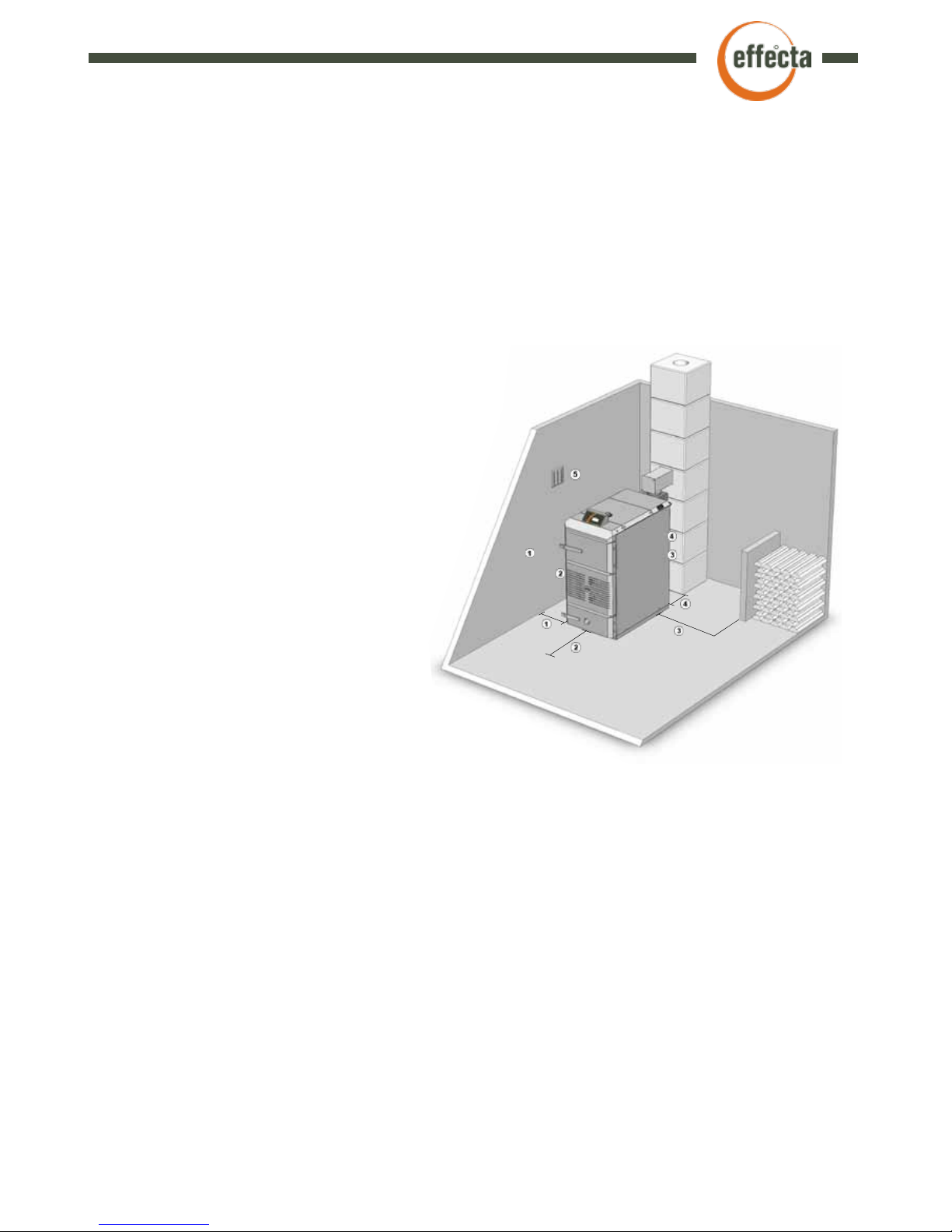
Set up
The boiler is positioned so that the surface temperature of flammable building material not
exceed 80°C. The boiler should be positioned at least 15 cm (1.) from the wall. The distance
from the smoke connection to a flammable wall with ignition protective covering must be at least
30 cm (4.). In order to clean the boiler, a minimum clear space of 1 metre (2.) is required in front
of the boiler and on the side at the convection section
and at any inspection panel in the chimney. A passage
with a minimum width of 0.5 (3.) m is required along
one of the long sides of the boiler.
The boiler room
The boiler must be installed in a boiler room or
boiler house. The ceilings and walls must be
fitted with ignition protective covering and
the floor must be made of non-combustible
material. Minimum ceiling height at the boiler
is 2 metres. The boiler room or boiler house
must be equipped with a fresh air intake
with the minimum dimensions 150 x 150
(5.) mm or with a sufficiently large free
sectional area to avoid low pressure in
the boiler room. It must be impossible to
close the air intake.
Accumulator tank
Be sure that the accumulator tanks are well insulated.
For the Effecta Lambda to function as optimally as possible, an accumulator
tank volume of 3000-5000 liters is required.
Chimney
The chimney should have a diameter of at least 150 mm. If your chimney is smaller, Effecta
should be consulted before installation. The draught in the chimney should be about 15 pa at
low temperatures. It is important that the chimney is tested and approved by a certified chimney
sweep before a new boiler is installed. If the chimney has a strong draught, a draught stabiliser
(see page 24.) may need to be installed for good boiler operation. If you have a tall chimney and
an outgoing flue gas temperature below 170°C, there is a risk of condensation in the chimney,
which can damage the chimney in the long term. A suitable temperature is 70-80°C one metre
down into the chimney. Ask your local chimney sweep for help to measure the temperature. If
the chimney is tall and has a large area, a draught that is too strong may mean high levels of
flue gas and overignition in the loading compartment. If this is the case, a counterdraught door
must be installed.
Page 6
6
Effecta AB - Västra Rågdalsvägen 21 - 434 99 Kungsbacka - +46(0)300 - 22320 - export@effecta.se
Laddomat 21-100 or equivalent
A Laddomat valve should always be mounted between boiler and
tank. It´s described further on page 12.
Automatic Shunt
The installation of a shunt automatic system on the radiator
circuit is always recommended. The automatic system senses
the temperature in a suitable location in the house and adjusts
the incoming temperature on the radiator circuit accordingly.
This measure can reduce your wood consumption by as much as
25 % and will improve your heat comfort level..
Expansion Vessel
The expansion vessel normally is tested for 6 bars. Highest
working temperature is 99°C. The vessel has a prepressure
of 2,5 bar. The volume should be approx. 10-12% of the total
volume of the system. An open vessel should have a volume of
5% of the total.
Safety Valve
The safety valve will release when pressure exceeds 1,5 bars.
When it opens, water will drip out of it and the pressure goes
down. Remember that the system is designed for a maximum
pressure of 1,5 bars, and shall under no circumstances be under
higher pressure.
Shunt valve
The shunt valve is to be mounted on the radiator circuit, and it´s
designed to mix the accumulator water and the return water from
the radiator to get the right temperature indoor. If mounting an
automatic shunt valve, read it´s instructions.
▀
Components
Page 7
7
Effecta AB - Västra Rågdalsvägen 21 - 434 99 Kungsbacka - +46(0)300 - 22320 - export@effecta.se
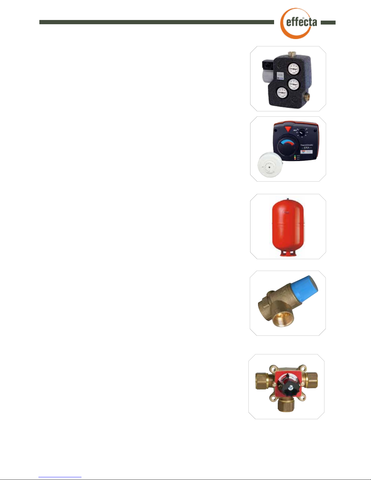
Valve Combination
The valve combination is mounted on the domestic water
circuit. It is purpose is to mix the hot water with cold before
it reaches the water taps. This is to avoid burns, and to keep
the taps and seals from being destroyed by to hot water.
Piping
Normally, copper piping is used for installing these systems.
Piping between boiler and accumulators should not be less
35mm. If the piping is longer than 6 meters to the first tank
it´s recommended to use 42mm.
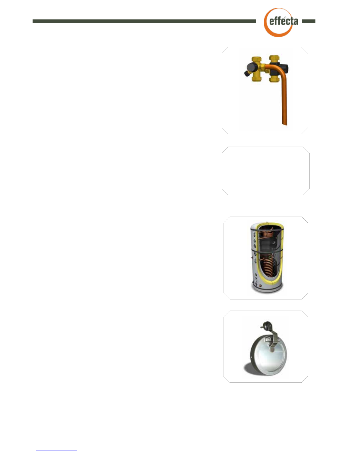
The Accumulator Tank
Effecta Lambda must always be connected to some sort of
accumulator tank, where the energy is stored, and where the
domestic water and the hot water to the radiators is taken.
The accumulator is described more thorough on page 13.
The Draft Stabiliser
If you have a tall and wide chimney, it is possible that you
have to install a draft stabiliser. You might notice that you
have an irregular combustion, puffing sounds from the boiler.
This happens when the chimney sucks too much air through
the boiler. The placement of the draft stabiliser in the chimney
should be approx. one meter above the connection to the
boiler. This is because you have an overpressure from the
fan, and if you place the draft stabiliser too close to the boiler
you might have smoke coming out of the stabiliser.
NOTICE!
Remember to insulate all of the
pipes in the boiler room.
▀
Components
Page 8
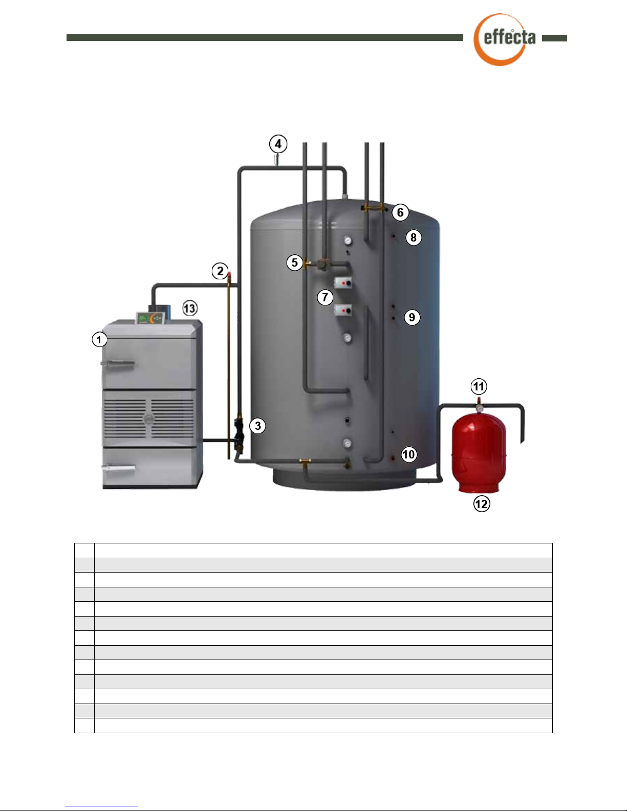
1 Wood log boiler Effecta Lambda 60
2 Safety valve
3 ESBE LTC 100 laddomat valve or similar
4 Air outlet
5 Automatic shunt valve
6 Valve combination for hot water
7 Electrical heaters
8 Possible connection from solar collectors
9 Possible connection from solar collectors
10 Return to solar collectors
11 Safety valve combination
12 Expansion vessel (at least 10% of the volume in the system)
13 Cooling coil (optional)
▀
System components
8
Effecta AB - Västra Rågdalsvägen 21 - 434 96 Kungsbacka +46 (0)300 - 22320 - export@effecta.se
Page 9

9
Effecta AB - Västra Rågdalsvägen 21 - 434 99 Kungsbacka - +46(0)300 - 22320 - export@effecta.se
Front Back Top
1 Inspection glass 1 Drain tap ½” 1 Control switch
2 Handle combustion chamber 2 Return pipe 1 ½” 2 Incoming pipe 1 ½”
3 Combustion chamber 3 Wing nut for detaching fan 3 Flue connection
4 Air intake 4 Splice connector fan 4 Cover plate for soot door
5 Damper motors (behind plate) 5 Fan 5 Sensor boiler temp
6 Handle loading compartment 6 Connecting box 6 Flue sensor
7 Loading compartment 7 Thermal protection
8 Control panel 8 Power supply for fan
9 Lambda sensor
▀
Component placement
Page 10

10
Effecta AB - Västra Rågdalsvägen 21 - 434 99 Kungsbacka - +46(0)300 - 22320 - export@effecta.se
Remember that during the first firing the boiler can feel sluggish and tough to fire. This is because
all the metal surfaces in the boiler are clean and cooled against the boiler water, the ceramics also
has some moisture that needs to dry. This uses energy from the wood, so the boiler can feel a bit
sluggish.
During the first firing, there is also a lot of oxygen in the water so it can sound as if it is simmering
in the boiler. This will go away when the system has been heated a few times.
The control switch should always be switched on. Place a handful of finely chopped dry wood at
the bottom of the loading compartment. Then take plenty of paper and place on top of the wood.
- Press button (A / startup) to start the fan and the charging pump, then ignite.
The lower door must be shut and the loading compartment door can be ajar but it can also be
closed. Test the way that suits you best. When the wood has ignited and there is a bed of embers,
the loading compartment can be filled with wood. Start by adding smaller pieces of wood at the
bottom and increase the size the further up in the loading compartment you go. Remember to stack
the wood carefully. It is important to get the best possible effect of the firing. When it has burned for
about 15 minutes, the flame will fill the bowl that you see in the inspection glass in the lower door.
The boiler burns at its best if the combustion is left on its own. It is therefore not appropriate to stir
the in the box during firing. If you open the door during firing, there is a risk of flashover in the box,
with poorer function as a result.
If you burn a lot of dry wood and have a strong draught in the chimney, you may hear a whispering
sound in the air dampers. This does not impair the boiler combustion or function, but to avoid this
you have to install a draft stabiliser that maintains a stable draught in the chimney.
NOTE: In case of a second insertion, there is a small risk of smoke emission. Therefore, wait until
the flue reaches a temperature just above 100°C. Open the door carefully to release any gas and
smoke from the loading compartment if necessary.
▀
The first firing
▀
Firing cycle
Start
Press the (START) button.
Fan and charging pump start,
the lambda probe is heated.
The dampers are adjusted
to Primary 70 % open and
Secondary 30 % open.
Operating phase
When the flue gas reaches
100°C , the dampers start to
regulate to achieve the set co²
level. The probe detects a value
every 20 seconds and adjusts
when the difference is + / - 0.5
% from the set value. If the co²
level must be increased, the
primary 10 % opens and the
secondary is reduced by 10 %.
If co² levels must be reduced,
the reverse occurs.
Reducing fire
When the co² level goes
down below 8 %, the
secondary damper shuts off
completely. And when the
flue gas temperature is below
90°C, the fan and circulation
pump shut off. The damper
closes completely. In order
to prevent downdrafts.
Safety
If the water jacket overheats
during firing, a protection will
stop the fan electronically
at 95°C. If the temperature
remains high, a mechanical
thermal protection is initiated.
This must be reset manually.
►
►
►
▬
Page 11

11
Effecta AB - Västra Rågdalsvägen 21 - 434 99 Kungsbacka - +46(0)300 - 22320 - export@effecta.se
▀
Menus
Showing carbon dioxide concentration, becomes
active at a flue temperature of 100°C.
Primary air damper is open 70%
Turning off the boiler.
Menu for firing
Boiler 47°C
Flue 45°C
B:stop
C:menu
P
_
S
_
CO
2
=
__.__ %
Secondary air damper is open 30%
Calibration of
Lambda sensor?
C:Next
A:Yes
Menu for adjustments
Calibration ongoing
Setting for
desired Co
2
: 13,5 %
C:Next
B:Top
A:Down
Total time: 143h
After cleaning 18h
Has cleaning been done?
C:No
B:Yes
Calibration must be
done before the first
firing. I.e. there must be
no fire in the boiler.
Total operating time
for the boiler.
Displays the operating
time after cleaning.
Press to reset.
C
C
A
Fired with / Running on pellets
C:No / NoB:Yes / Yes
C
C
The pump stops when ue = 85°C
B
The pump starts when ue
= 95°C
C:Next B:Top
A:Down
C:Next B:Top
A:Down
C
Use the fan
B:No / No
A:Yes / Yes
C
Charging pump start
temperature.
Charging pump stop
temperature.
In the case of a weak
draught, the boiler fan
can be used for pellets
burning.
Normally the concentration does not change. If the
wood is extremely dry, it can be reduced or the reverse in the case of damp wood.
Has cleaning been done?
C:NoB:Yes /
C
Effecta Woody Lambda
Boiler 47°C
Flue 45°C
A:start
C:menu
P
_
S
_
Starts the boiler
Indicates boiler temp.
Indicates flue
gas temp.
Damper status.
Damper status.
Entry menu.
Page 12

12
Effecta AB - Västra Rågdalsvägen 21 - 434 99 Kungsbacka - +46(0)300 - 22320 - export@effecta.se
▀
Function Laddomat 21-100
5 Thermal valve
6 Check valve for natural circulation
7 Circulation pump
8 Spring with housing
9 Filling valve for the system
1. Start-up when the boiler
temperature is below 78°C, the
cartridge has not opened, the
beam for self-circulation is tight
against the accumulator tank due
to pump pressure.
2. Operational phase when
the boiler temperature exceeds
78 °C, the cartridge opens
and mixes cold water from the
accumulator tank. Boiler water
return temp is normally about
70°C. At 90°C from the boiler,
the Laddomat normally gives
66°C back to the boiler.
3. Final phase When the
accumulator tank is fully charged,
hot water will enter on the cold
side of the Laddomat. Then the
plunger opens fully toward the
accumulator tank and closes the
pipe toward the top of the boiler.
All flow now goes to the
accumulator tank. This feature
is important for the accumulator
tank to charge fully.
4. Self-circulation In the
event of loss of electricity or
failure of the circulation pump,
the check valve is opened for
self-circulation. This will normally
prevent boiling unless the
accumulators are fully charged or
the piping presents an obstacle
for circulation.
Page 13

13
Effecta AB - Västra Rågdalsvägen 21 - 434 99 Kungsbacka - +46(0)300 - 22320 - export@effecta.se
▀
Sleeve placement in solar accumulator tank
165
215
306
376
584
714
866
946
1075
1274
1456
1534
1616
150
1889
1
3
4
6
7
8
9
10
11
12
14
15
5
13
2
16
18
19
17
20
21
ACKUMULATOR 750 BBS
MÅTT OCH PLACERING
EFFECTA AB
Västra Rågdalsvägen 21 - 43496 kungsbacka
Tel: 0300-22320 - Fax: 0300-22395
E-post:info@effecta.se - www.effecta.se
010-05-22
V50-05-67
E.A
EXPLANATION
1. SWEEP 1500 X 750 MM
2. 1 1/4”70 MM / CHARGE
3. 1/2” 45 MM / THERMOMETER
4. 1/2” 45 MM / SENSOR SOLAR
5. 1 1/4”70 MM / DOCKAGE / FLOW RADIATOR
6. 2” ELECTRICAL HEATER
7. 2” ELECTRICAL HEATER
8. 1/2” 45 MM / THERMOMETER
9. 1 1/4”70 MM / DOCKAGE
10. 1/2” 45 MM / THERMOMETER
11. 1”70 MM / RETURN UNDERFLOOR HEATING
12. 1/2” 45 MM / SENSOR SOLAR
13. 1/2” 45 MM / THERMOMETER
14. 1 1/4”70 MM / RETURN BOILER / DOCKAGE
15. 1/2” 70 MM / DRAIN
16. 22 MM CU / HOT WATER OUT
17. FRAMES WITH 18
18. FRAMES WITH 17
19. COLD WATER IN
20. 18 MM CU / SOLAR COLLECTORS RETURN
21. 18 MM CU / SOLAR COLLECTORS FLOW
Page 14

14
Effecta AB - Västra Rågdalsvägen 21 - 434 99 Kungsbacka - +46(0)300 - 22320 - export@effecta.se
ELECTRICAL DIAGRAM
EFFECTA LAMBDA 35/60
EFFECTA AB
Västra Rågdalsvägen 21 - 43496 kungsbacka
Tel: 0300-22320 - Fax: 0300-22395
E-post:info@effecta.se - www.effecta.se
011-12-20
50-12-08
E.A
L1
N
Ground
CHARGE PUMP
OH 95 ˚C
POWER 230 V
LAMBDA SENSOR
BLACK
GREY
BLUE
WHITE
RED
BROWN
BROWN
ORANGE
YELLOW
RED
BROWN
ORANGE
YELLOW
RED
M
M
RED
RED
M
DAMPER PRIMARY
DAMPER SECUNDARY
FUSE 2A
GREEN
GREEN
---
---
N N N
L1
N
+-
+ +
+
N
M
FAN MOTOR
CONDENSER
FLUEGAS
BOILER TEMPERATURE
POTENTIOMETER
CONTROL SWITCH
L1
1. 2.
4. 5.
CONVERTER
N
BLUE
BLUE
BLUE
N
L1
PELLET BURNER
NOT STANDARD CONNECTION
OH 95 ˚C
▀
Electrical installation
Page 15

15
Effecta AB - Västra Rågdalsvägen 21 - 434 99 Kungsbacka - +46(0)300 - 22320 - export@effecta.se
▀
Cleaning and service
Afterburner chamber and combustion chamber
The afterburner chamber (1) is located
behind the lower door. It is important to
keep it clean for maximum power and
performance. The chamber slides on two
rails under the ceramics tray. Pull out
and empty the chamber from soot and
ashes approximately every third firing.
When you do a major cleaning, scrape the
space under the ceramics clean as well
as the whole space where the afterburner
chamber is located. Do not forget to reach
all the way into the back where the ashes from
the tubes collect.
Tubes
In order to clean the tubes, lift the rear top plate
(1.), then loosen the wing nuts (2.), that keep the
soot door in place (3.). Remove the 12 spirals
from the tubes (4.), and use the supplied brush to
clean the tubes.
Loading compartment
Start by removing the grate sticks (1.) located at the bottom
of the ceramics. Scrape off the charcoals and ash down into
the slits in the ceramics. The loading compartment walls (2.)
normally have a thin layer of tar, this is normal and does not
need to be scraped off. Do not forget to check that there are
no ashes in the hole where the primary air (3.) is released
into the loading compartment.
Cleaning interval
1. Loading compartment, 40 hours firing.
2. Tubes 40 hours firing.
3. Afterburning chamber,15 hours firing.
4. Fan about 3 times a year.
5. Cleaning lambda sensor once per year.
6. Air distributor secondary air, 40 hours firing.
7. Combustion chamber, 40 hours firing.
8. Check the gaskets once per year.
9. Flue connection and elbow, 40 hours firing.
10. The holes where the primary air is released, once
per year.
Page 16

16
Effecta AB - Västra Rågdalsvägen 21 - 434 99 Kungsbacka - +46(0)300 - 22320 - export@effecta.se
Lambda sensor
The lambda sensor is located in the flue
connection and measures the oxygen content
in the flue gas. Once a year the Lambda probe
should be unscrewed from its bracket and
cleaned from any soot that has amassed. Use a
brush. Do not tap it against anything, then it will
brake.
Fan
In normal wood consumption, you should clean
the fan three times a year. Loosen the wing nuts
(1.) located at the back of the fan housing. Pull
out the fan, clean the fan wings (2.) from dust
and soot. If the fan is not cleaned, the boiler
will lose power, resulting in slower heating and
lower combustion.
Secondary air
In the air gap where the flame is drawn down,
there is a metal plate with holes (1.) Clean the
plate after about 40 hours firing. Brush / scrape
away the dust and ashes. If the holes become
clogged up, combustion will deteriorate
significantly.
(In the picture the lower door is viewed from an
angle from below)
▀
Cleaning
Gaskets
The door gaskets must fit tightly against the
frame, if the doors leak the boiler heats less
efficiently. Make sure that the doors' gaskets
seal tightly against the frames. If the gaskets do
not seal tightly, the boiler will burn less efficiently.
If the doors need to be adjusted, see (p. 20).
Page 17

17
Effecta AB - Västra Rågdalsvägen 21 - 434 99 Kungsbacka - +46(0)300 - 22320 - export@effecta.se
▀
Hydraulic scheme
EFFECTA LAMBDA 60 ACCUMULATOR
AND SOLAR
EFFECTA AB
Västra Rågdalsvägen 21 - 43496 kungsbacka
Tel: 0300-22320 - Fax: 0300-22395
E-post:info@effecta.se - www.effecta.se
010-05-22
V50-05-77
E.A
EFFECTA ST2
RADIATORS
30.
2.
27.
1.
31.
28.
29.
5.
16.
1. AIR SEPARATOR
2. SENSOR SOLAR (T1)
3. CIRCULATION PUMP RADIATOR
4. BIVALENT SHUNT
5. AIR SEPARATOR
6. LOADING / DOCKING
7. THERMOMETER
8. SENSOR SOLAR ( T2 )
9. RADIATOR SEK / DOCKING
10. ELECTRICAL HEATER
11.TERMOMETER
13. RADIATOR PRIMARY / DOCKING
14.POSSIBLE SENSOR
15. RETURN RADIATOR
16. SENSOR SOLAR ( T3 )
17. THERMOMETER
18. RETURN BOILER
19. HOT WATER OUT
20. CONNECT TO 21
21. CONNECT TO 20
22. COLD WATER IN
23. LOADING SOLARS HIGH
24. RETURN SOLAR LOW
25. LOADING SOLAR LOW
26. RETURN SOLAR LOW
27. 3-WAY VALVE / ALT. THERMAL VALVE (61)
28. 3-WAY VALVE / ALT. THERMAL VALVE (48)
29. CIRKULATION PUMP SEK. SOLAR
30. DRAIN COCK
31. EXPANSIONS VESSEL WITH SAFETY GROUP
32.THERMAL VALVE WITH PUMP
33. SAFETY VALVE 1,5 BAR
34. MIXING VALVE
35. EXPANSIONS VESSEL WITH SAFETY GROUP
3.
34.
19.
22.
6.
7.
8.
9.
10.
11.
12.
13.
14.
15.
17.
18.
23.
24.
25.
26.
4.
21.
20.
6.
35.
RC
ACCUMULATOR
33.
WOODY LAMBDA 60
32.
EXPLANATION
COLD WATER
Page 18

18
Effecta AB - Västra Rågdalsvägen 21 - 434 99 Kungsbacka - +46(0)300 - 22320 - export@effecta.se
EFFECTA LAMBDA 60
EFFECTA AB
Västra Rågdalsvägen 21 - 43496 kungsbacka
Tel: 0300-22320 - Fax: 0300-22395
E-post:info@effecta.se - www.effecta.se
011-10-11
V50-04-46
E.A
TECHNICAL DATA
1. FLOW ACCUMULATOR 1 1/2”
2. RETURN ACCUMULATOR 1 1/2”
3. DRAIN COCK 1/2”
LEGEND
Width
Depth incl. Flue connect.
Height
Weight
Maximum pressure
Flue angle (extra)
Smoke pipe diameter
Floor to cc flue conncet.
Water volume
Log length
Recommended draft
Min. chimney area
Electrical connection
Sheet tickness mantle
Sheet tickness firebox
Loading volume
Loading compart. depth
Power fan
Power
Max. operating temp.
Firebox opening
Rec. tankvolume
750 mm
1330 mm
11340 mm
540 kg
1,5 bar
150x180x630 mm
180 mm
1365 mm
135 liter
500 mm
15 pa.
180 mm
230 VAC
4 mm
5 mm
195 liter
550 mm
100 W
60 kW
99 gr
490x310 mm
3000-5000 liter
▀
Measurements
Page 19

19
Effecta AB - Västra Rågdalsvägen 21 - 434 99 Kungsbacka - +46(0)300 - 22320 - export@effecta.se
▀
Ceramics
1 Grate stick
2 Top left
3 Top right
4 Distribution plate secondary air
5 Bottom left
6 Bottom right
7 Afterburner chamber
8 Widener lower
9 Widener upper
The ceramics tray is installed in the loading compartment. The purpose of the ceramics is to
separate the different combustion zones in the boiler. It is important to monitor the tray since
it is a wear part. In normal conditions, the ceramics tray will last for 6-8 years. When the tray is
used up, combustion and efficiency deteriorate significantly.
Page 20

20
Effecta AB - Västra Rågdalsvägen 21 - 434 99 Kungsbacka - +46(0)300 - 22320 - export@effecta.se
▀
Door adjustment
1. Adjustments in depth
If the gasket does not seal tightly against the hinge
side, loosen the two bolts that hold the hinge in place
of the door frame. Release the bolts around two turns
and adjust the door inwards to tighten the lid and inverted to release the pressure on the gasket.
2. Vertical displacement
To centre the gasket on the door frame in height,
loosen the two bolts on the outside of door. Release
the bolts around two turns and adjust the door.
Approval of the door locking
If the gasket does not seal tightly on the handle side,
loosen the two bolts (1.) that hold the bracket in place.
Loosen around two turns and slide the latch inwards to
tighten the lid and outward to release the pressure. If
the door handle is not in the vertical position with the
flip closed, you can adjust the bolt (2.) up or down to
change position.
There are a number of ways to adjust the hatch. In the pictures below you can see the hinge
on the door. After some use, some adjustments maybe is needed so the gaskets do not draw
extra air to the boiler.
3. Adjustment sideways
To centre the gasket on the door frame to the side,
loosen the two above the number of millimetres that
the adjustment needs. Tighten the short side door with
two bolts.
Page 21

21
Effecta AB - Västra Rågdalsvägen 21 - 434 99 Kungsbacka - +46(0)300 - 22320 - export@effecta.se
▀
Rotate the door
As standard Effecta Lambda is delivered with door hinges on the right side. If you need to replace the door hanging follow instructions below.
Upper hatch
1. Start by loosening the two M12 bolts that hold the hatch in the against the frame. Remember to have a shelter over the hatch to avoid scratches in the paint with continued work.
2. Also loosen the two M12 bolts that hold the locking device in place. The new lock is supplied with boiler, the existing is not to be used.
3. Remove the two M12 bolts that hold the thermal insulation in place. Manage the insulation
carefully as it easily gets splinters.
4. Remove the two door gaskets.
5. Then remove the two small bolts that hold the angle (6) which is the upper insulation strip
in place.
6. Reassemble the thermal insulation into the two holes located above the original holes. Replace gaskets and then finally the angle plate. Remember not to twist gasket when refitting.
Lower hatch
The lower door is rotated by following step (1-2).
Page 22

22
Effecta AB - Västra Rågdalsvägen 21 - 434 99 Kungsbacka - +46(0)300 - 22320 - export@effecta.se
1 Damper motor 5 Set screw
2 Stop pin 6 Motor shaft
3 Air damper 7 Bracket motor
4 Distance 8 Air box
▀
Air dampers
To access the damper loosen the four screws holding the
cover plate in front damper motors in place. Open the two
doors to access the screws.
▀
Converter
Under the middle roof of the boiler there is a
converter which supplies the circuit boards with
power. The power level is preset at the factory,
but sometimes an adjustment may be needed. If
so, the light flashes on the display. Features such
as fans can also be affected at low voltage. Adjust
the brightness using the knob (1.) located on the
converter clockwise 1-3 mm. If the LED (2.) is not
lit, the converter is probably not functioning.
Page 23

23
Effecta AB - Västra Rågdalsvägen 21 - 434 99 Kungsbacka - +46(0)300 - 22320 - export@effecta.se
▀
Trouble shooting
Problem Possible errors Action
There is smoke emission during ignition.
The fan is turned off. Press ( start new firing ).
Smoke is seeping through the doors. A gasket is leaking. Adjust the doors.
The fan will not start. An electronics malfunction.
Thermal protection switched on.
Contact the factory.
The fan will not stop. The boiler has not had a flue gas
temperature higher than 100°C during
firing.
The boiler will stop within 1 hour.
Tar in the convection section. A sooty loading compartment.
The Lambda sensor needs cleaning.
Damper motor defective.
Clean the boiler.
Clean the Lambda sensor.
Contact the factory.
Little or no heat is transferred to the
accumulator tank.
Probably air in the system.
Poor quality wood.
Fill the system thoroughly.
Change to dryer wood, or chop the
wood into smaller pieces.
The boiler has a low output and is
sluggish.
Moist wood or too little draught in the
chimney.
The boiler may need to be cleaned.
Try drier wood.
Clean the boiler and fan.
The charge pump creaks or thumps,
and sometimes stops pumping.
Probably air in the system.
Low system pressure.
Follow the Laddomat instructions.
Increase the pressure.
The pressure drops in the system. There is a leak in the system. The wa-
ter in the vessel has evaporated.
Wrong first pressure in the pressure
vessel.
Fill up with water and ventilate.
Adjust the pressure.
The CO ² level is abnormally high. The lift dampers have shifted. Adjust the dampers.
The CO ² level is abnormally low. The lift dampers have shifted, the fire is
extinguished.
Adjust the dampers, check the fire.
The air dampers do not start regulating.
Flue gas temperature is below 100°C,
and the fire is extinguished. Deficient
flue gas sensor.
Check the fire.
Noise from the fan. The cooling wing scrapes against the
boiler. The bearings in the fan have run
out.
Check the cooling wing on the shaft
between the motor and fan. Contact
your installer.
The display is blinking. Low or high voltage to the circuit board. Adjust the converter.
High flue gas temperature. Soot in the tubes. Clean the boiler.
CO2 is not changing from 17-21% Dirty lambda sensor or broken
Electrical connections faulty
Clean the sensor
Check all connections
To run without sensor press A and B at
the same time. Then the dampers open
50/50 and the sensor is not used. Contact your retailer or Effecta for service
Page 24

Declaration of conformity:
Effecta Pannan AB
Västra rågdalsvägen 21
SE-434 99 Kungsbacka
The declaration refers to the responsibility of the product:
Effecta Woody: Wood boiler
Number: 02-756697-02
Directive:
89/336/EEC with supplements 92/31/EEC, 93/68/EEC (EMC)
73/23/EEC with the supplement 93/68/EEC (LVD)
97/23/EC (PED)
Harmonised standards:
SS-EN 60204-1 Electrical equipment for industrial machines -
Part 1: General requirements related to the machine and LVD.
SS-EN 50081-2 For emission industry (EMC standards)
SS-EN 50082-2 For immunity industry (EMC standards)
Kungsbacka 12-12-2004
Erik Andersson
Effecta AB
 Loading...