

Effecta Komplett III Owner's Manual
Rev. JG. 014-09-03
INSTALLING
MAINTENANCE
SERVICE
ASSEMBLY
20
25
35
Light
20
25
35
EFFECTA KOMPLETT III

Effecta AB Västra Rågdalsvägen 21 434 99 Kungsbacka Sweden +46-300 - 22320 info@effecta.se
2
We at Effecta would like to thank you for putting your trust in us when choosing your new
boiler. The ”Effecta Komplett III” has been developed to give you maximum performance,
comfort and quality. In order to get the best results from your boiler, we suggest that you
follow the recommendations in this installation guide.
Checking your delivery
Check that the boiler has not been damaged during transportation. If the boiler has been
damaged, you must report this to the transportation company immediately.
Your safety
If you discover any faults or defects in our products, it is important that you report them as
quickly as possible to your installation engineer, so that the fault can be rectified. Make sure
that there are no flammable materials close to the boiler, to help prevent risk of fire. You must
use your own judgement when operating the pellet boiler. Remember that the hatches and
some surfaces can get hot. You must take caution to avoid being burnt.
The user
It is the user´s responsibility to operate the boiler according to our instructions. If you do
not operate and maintain your boiler correctly, the environmental impact of the boiler will be
greater, its efficency will be reduced and the service life of some components will be shorter.
If there is anything that you are not sure about, please contact your installation engineer or
Effecta for advice.
Warranty
The warranty takes effect from the date on which the boiler is installed. The supplied
installation form must be completed and returned to Effecta. You can find the other guarantee
terms on (page 3).
▀
Scope of delivery
Please check all components delivered.
The standard delivery as follows:
- Effecta Komplett III boiler
- Cleaning handle with brush
- Rake with scraper
- Fluetube
- Draft stabiliser (optional)
- Turbulators, 8pcs.(mounted)
- Drain cock
- Shunt valve + motorized shunt control, not in ”Light” version
- Electrical heater 3-9 kW (mounted), not in ”Light” version
- Thermostatic mixer valve, not in ”Light” version
- Room thermostat, optional in ”Light” version
- Outdoor sensor, optional in ”Light” version
▀
Introduction
3
Effecta AB Västra Rågdalsvägen 21 434 99 Kungsbacka Sweden +46-300 - 22320 info@effecta.se
▀
System data:
▀
Warranty
Installer:
Date:
Electrical installer:
Effecta products are guaranteed to be free of defects in materials and workmanship. The main
body has a 5 year warranty against leakage of water and all other parts have a 2 year warranty.
The warranty also covers original spare parts. Any faulty products will be replaced or repaired at
the discrimination of the retailer or Effecta. If a faulty product is detected, Effecta is entitled to
replace it with a new or reconditioned product of the same or a similar type.
If you have a complaint, you must contact your retailer before starting any servicing work.You
must submit your complaint without delay. You must always state the type of product, the date of
purchase and the serial number.
Otherwise the heating and plumbing industry's current regulations apply in case of complaints.
Guarantee terms:
The guarantee is valid on condition that:
- The boiler and the heating system have been installed in accordance with the installation instructions
and in a professional manner.
- The location where the product is installed is suitable for the purpose.
The guarantee does not cover:
- The overall functioning of the heating system, costs incurred as a result of the heating system
being out of operation, or the cost of the temporary replacement of products.
- Damage or injury caused by negligence during the installation or by operating the boiler in a
way which conflicts with the installation and user instructions.
- Damage caused by abnormal wear, incorrect operation and maintenance.
- Damage caused by the use of non-original spare parts.
- Damage caused by the boiler being positioned in an unsuitable location.
- Damage caused by vermin.
Effecta AB Västra Rågdalsvägen 21 434 99 Kungsbacka Sweden +46-300 - 22320 info@effecta.se
4
▀
Contents
2 Introduction
2 Scope of delivery
3 Warranty
3 Terms of warranty
3 System data
4 Contents
5 In general
5 Symbols in this document
5 UK Clean Air Act
6 To the installer
7 The components
7 Exploded view, burner
8 Safety and function
9 The safety systems
10 Placement of components
11 The fuel
11 The chimney
12 Cleaning system boiler
13 Cleaning system burner
14 The mothterboard
15 1,2 or 3 Phase connection
16 Connection expansion boards
17 Electrical connection
18 The menu system
19 The menu system
20 The menu system
21 The menu system
22 The menu system
22 Alarms at disruption
22 Ignition phase of the burner
23 First start
23 Tuning the boiler
24 Tuning the burner
25 Hot water
25 Valve combination
26 Shunt control
27 Adjustment of heating curves
28 Examples of curves
29 Service and cleaning
30 Replacing the combustion fan
31 Servicing the flame sensor
31 Overheated fall shaft
32 Charging the igniter
33 Cleaning the rear housing and outer tube
33 Mounting and adjusting of the draft stabiliser
34 Mounting the auger
35 Trouble shooting
35 The sensors
36 Documentation of settings
37 Dimensions
38 Technical data
39 Hydraulic scheme
40 Hydraulic scheme extra hot water
41 Hydraulic scheme buffer system
42 CE
5
Effecta AB Västra Rågdalsvägen 21 434 99 Kungsbacka Sweden +46-300 - 22320 info@effecta.se
The Boiler
Effecta Komplett III is a boiler which is to be fueled with wood pellets. No other kind of fuel is
allowed to be used. Not logs or oil.
Disassembly and disposal
It will be many years before your Effecta boiler is worn out, but it is important that you follow
the regulations in force at the time concerning disassembly and disposal of your boiler.
The fuel
The boiler should burn 6 mm pellets which come either in sacks or are supplied by bulk truck.
If you have built a bulk storage, you should follow the current recommendations to ensure that
the quality of the pellets does not deteriorate. Never use pellets which do not meet European
pellet standards, as this may result in problems in operating the burner.
▀
In general
Information
This symbol is shown with info to the installer which can be important to know and
understand. Neglecting this information can affect the performance of the product.
▀
Symbols in this document
Dangerous electricity
This symbol means that extra caution should be taken otherwise serious personal injury
might occur. When maintaining the product where this symbol is present the power must
be disconnected. All electrical wiring must be done by a Professional and comply with
current building regalation.
▀
United Kingdom ”Clean Air Act”
Under the Clean Air Act local authorities may declare the whole or part of the district of the
authority to be a smoke control area. It is an offence to emit smoke from a chimney of a building, from a furnace or from any fixed boiler if located in a designated smoke control area. It is
also an offence to acquire an ”unauthorised fuel” for use within a smoke control area.
Unless it is used in an ”exempt” appliance (”exempted” from the controls which generally apply in the smoke control area). The Secretary of State for Environment, Food and Rural Affairs
has powers under the Act to authorise smokeless fuels or exempt appliances for use in smoke
control areas in England. In Scotland and Wales this power rests with Ministers in the devolved
administrations for those countries. Separate legislation, the Clean Air (Northern Ireland) Order
1981, applies in Northern Ireland. Therefore it is a requirement that fuels burnt or obtained for
use in smoke control areas have been ”authorised” in Regulations and that appliances used to
burn solid fuel in those areas (other than ”authorised” fuels) have been exempted by an Order
made and signed by the Secretary of State or Minister in the devolved administrations.
Your local authority is responsible for implementing the Clean Air Act 1993 including designation and supervision of smoke control areas and you can contact them for details of Clean Air
Act requirements”
Effecta Komplett has been recommended as suitable for use in smoke control areas when burning wood pellet.
Effecta AB Västra Rågdalsvägen 21 434 99 Kungsbacka Sweden +46-300 - 22320 info@effecta.se
6
▀
To the installer
It is time to install the Effecta Komplett III pellet boiler. Please follow the examples we provide
for a safe installation. After installation, be sure to instruct the customer on how the heating
system and the boiler work, in order to avoid unnecessary complications in the future. Please
fill out ”Documentation of Settings”(pg35).
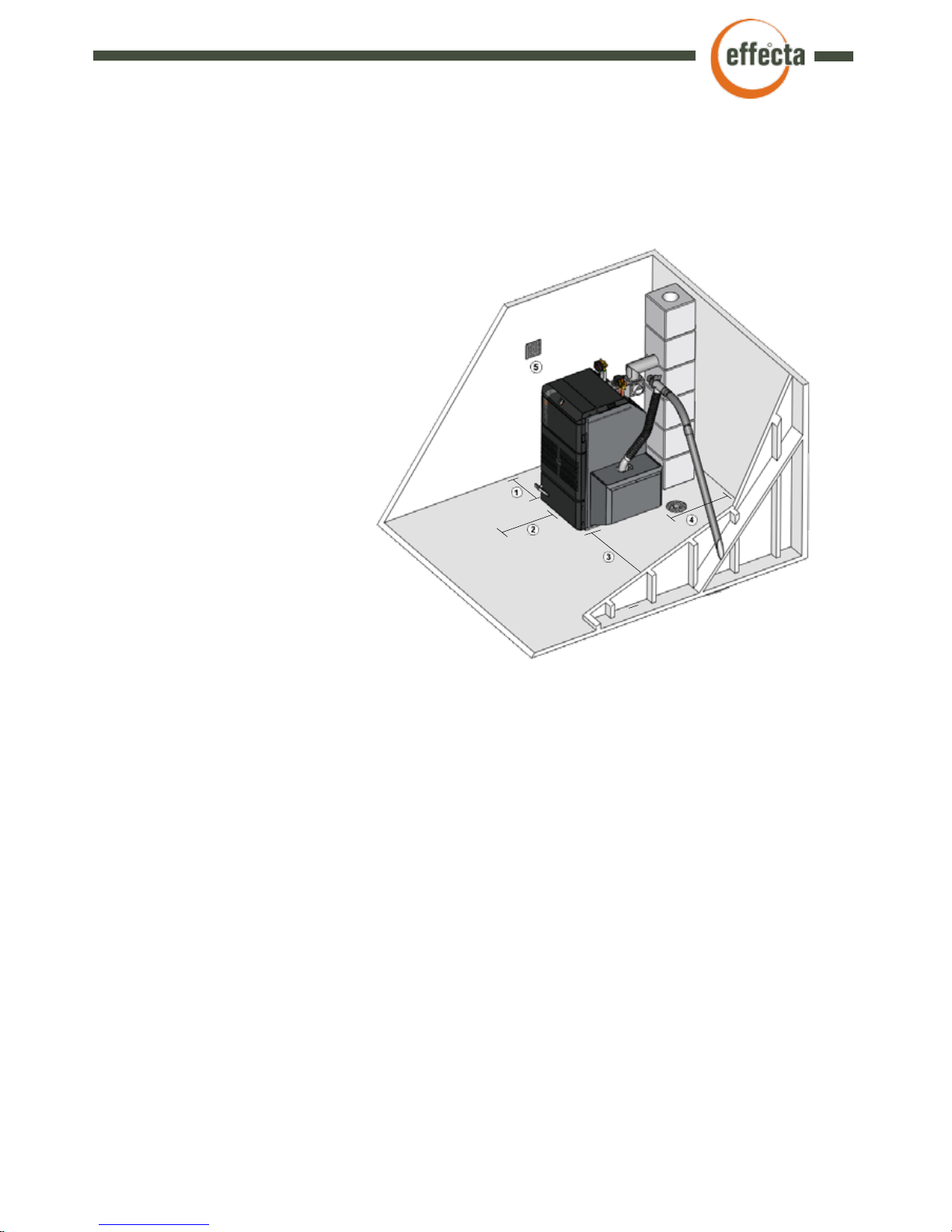
Set up
The boiler is positioned so that the
surface temperature of flammable
building material does not exceed
80°C. The boiler must be placed on a
non combustible floor, for example
concrete or tiles. The boiler should
be positioned at least 15 cm (1)
from the wall. The distance from
the flue tube on the boiler to
a flammable wall with ignition
protective covering must be
at least 30 cm (4). In order to
clean the boiler, a minimum
clear space of 1 metre (2)
is required in front of the
boiler and on the side at the
convection section and at
any inspection panel in the
chimney. A passage with a
minimum width of 0.5 (3)
m is required along one of
the long sides of the boiler. Check the regulations of your country in order to place the pellet
hopper on a approved distance from the boiler.
The boiler room
The boiler must be installed in a boiler room or boiler house. The ceilings and walls must
be fitted with ignition protective covering and the floor must be made of non-combustible
material. Minimum ceiling height at the boiler is 2 metres. The boiler room or boiler house
must be equipped with a fresh air intake with the minimum dimensions 150 x 150 (5.) mm or
with a sufficiently large free sectional area to avoid low pressure in the boiler room. It must be
impossible to close the air intake.
Chimney
The draught in the chimney should be about 15 pa at low temperatures. It is important that
the chimney is tested and approved by a HETAS approved installer before a new boiler is
installed. If the chimney has a strong draught, a draught controller (see page 32) may need
to be installed for good boiler operation. If you have a tall chimney and an outgoing flue gas
temperature below 170°C, there is a risk of condensation in the chimney, which can damage
the chimney in the long term. A suitable temperature is 70-80°C one metre down into the
chimney. Ask your local chimney sweep for help to measure the temperature. If the chimney
is tall and has a large area, a draught that is too strong may mean high levels of flue gas and
overignition in the ash compartment. If this is the case, a draft stabiliser must be installed.
7
Effecta AB Västra Rågdalsvägen 21 434 99 Kungsbacka Sweden +46-300 - 22320 info@effecta.se
The shunt valve
The shunt valve controls the heat supply from the boiler to the radiator circuit.
Effecta Komplett III is fitted with motorised shunt control. The room temperature can be
adjusted on a scale on the thermostat. An automatic system will significantly reduce fuel usage
and provide a more comfortable environment.
The thermostatic mixer valve
The mixing valve is used to ensure that the temperature of the hot water in your shower and
elsewhere in the house is comfortable. Set the system to the temperature you want by turning
the thermostat between +/-.
The burner
The burner is mounted on the left or right side. The burner heats the water in the boiler which
provides heat to the domestic and hot water.
The turbulators
In the tubes in the heat exchanger hangs the turbulators. The turbulator`s function is to transfer
heat from flue gas to boiler water. They must always be placed in the boiler. If the flue gas
temperature should be to low, the turbulators can be cut off. Always contact the installer before
doing this.
The sealings
The seals on the hatches must be checked every year. If the hatches do not seal properly, the
efficiency and the combustion process of the boiler will deteriorate.
▀
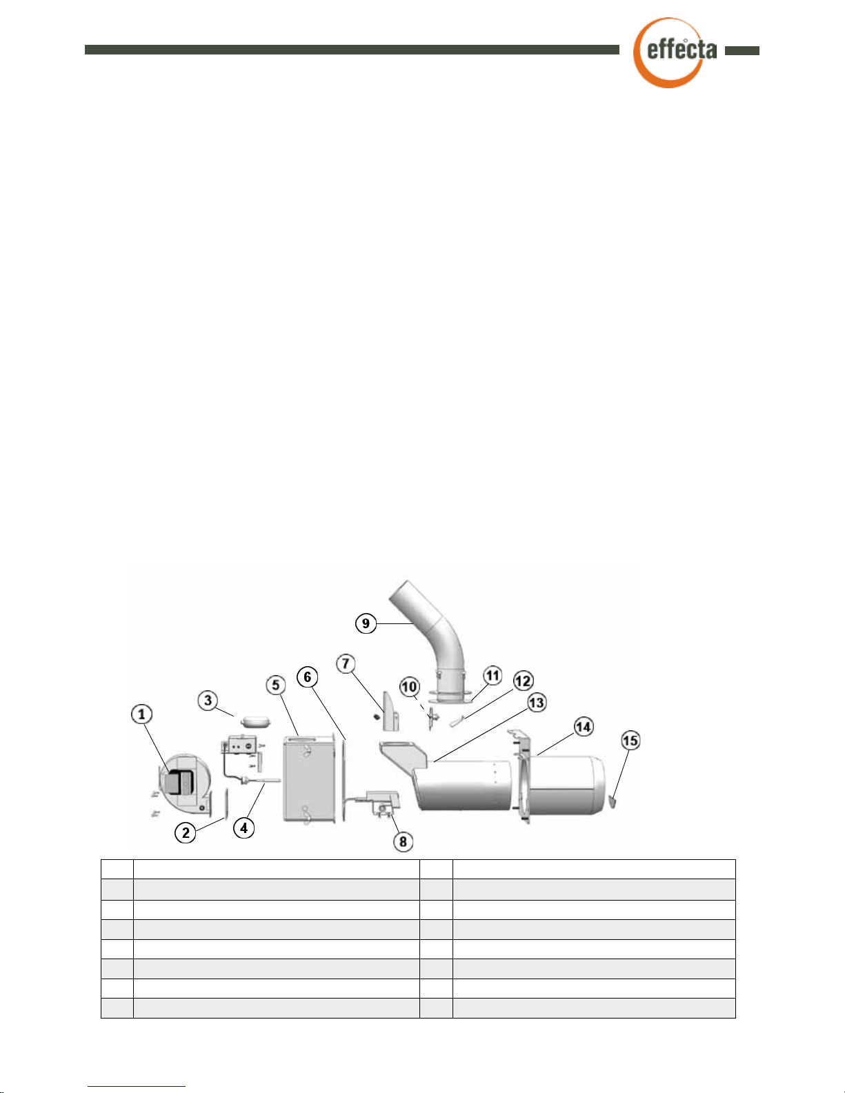
The components
1. Combustion fan with tachometer 9. Fall shaft
2. Fan seal 10 Overheating protection
3. Under pressure switch 11 Seal for fall shaft
4. Flame sensor 12 Pellet retarder
5. Rear housing 13 Inner combustion tube
6. Rear housing seal 14 Outer combustion tube
7. Cover for overheating protection 15 Stop plate
8. Ignition console
▀
Exploded view, burner

Effecta AB Västra Rågdalsvägen 21 434 99 Kungsbacka Sweden +46-300 - 22320 info@effecta.se
8
▀
Safety and function
Before using the product, the owner and/or other user must read and understand the content
in this manual. The directions must be followed. This is to make sure that the product is
functioning correctly and accidents and injuries are avoided. Incorrect use or burner adjustment
can result in damage to property and personal injury or poorer performance in the product.
The boiler room where the product is installed, the chimney and other components must be
approved according to current legislation.
The commisioning of the product must be made by a professional, according to Effectas
directions and current legislations. Controls and tuning of the product should be made by a
professional. A chimney sweeper should also be contacted when commisioning the product.
The electrical connections must be done by a qualified electrician, according to Effectas
instructions in this manual.
The casing outside of the burner must always be fitted on the boiler when the boiler is
connected to the electrical power. Before cleaning and maintenance of the product, make sure
it is disconnected from the main power.
It is strictly forbidden to open any doors when the burner is igniting. If any door or hatch is
opened when the burner is running, great caution must be taken. Any kind of interference or
using of other than original spare parts can result in damage to the product or person. It also
removes Effecta from any liability.
It is strictly forbidden to make any changes or alterations on the boiler without prior approval
from Effecta. If any changes are made, the safety functions, or any other function, might not
work as it is supposed to, and all warranties and liabilites from Effecta are cancelled.
This manual should be kept during the whole life span of the product. Any updates will be
reported on the Effecta web page: www.effecta.se.

9
Effecta AB Västra Rågdalsvägen 21 434 99 Kungsbacka Sweden +46-300 - 22320 info@effecta.se
The overheat protection on the fall shaft
This stops the feeding if the fan temperatures gets too high. Reset is made manually.The cover
must always be in place when connected to main power. It only cuts the power to the auger.
Flame sensor
The flame sensor monitors the flame in the burner. If the flame disappear for a set time during
operation the burner stops and goes into cooling phase.
Overheat protection on the boiler
There is overheat protection on the boiler which cuts the power to both the boiler and the burner
if the temperature in the boiler exceeds 95°C.
Power outage
After a power outage the control system remembers where in the sequence the burner was. If it
was in the ”Run” mode, the fan blows for four minutes to burn out any pellet rests. Then it goes
into normal mode.
Under pressure switch
If the under pressure in the combustion chamber is lost, the auger stops and no more pellets is
fed into the burner. If the soot door not is closed, the under pressure is lost and the burner will
switch off. The auger starts when underpressure is obtained again.
▀
The safety systems
Effecta AB Västra Rågdalsvägen 21 434 99 Kungsbacka Sweden +46-300 - 22320 info@effecta.se
10
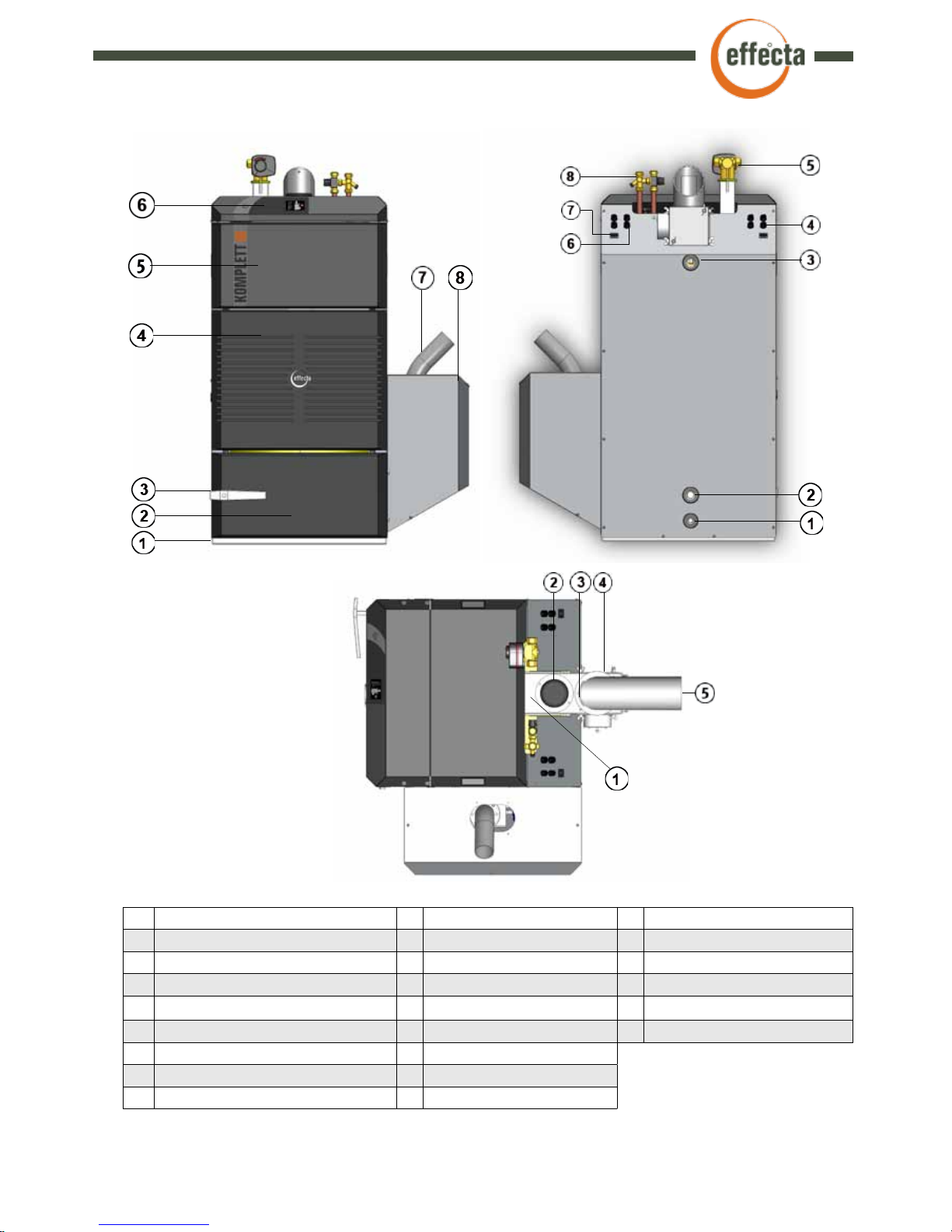
▀
Placement of the components
Front Back Top
1 Adjustable feet 1 Drain cock 1/2” 1 Flue gas measuring point
2 Soot door 2 Return hot water circuit 1” 2 Flue fan
3 Handle soot door 3 Flow hot water circuit 1” 3 Soot door flue tube
4 Front cover 4 Hoses electrical wiring 4 Soot door 3 pc.
5 Over heat protection (behind front) 5 Shunt valve * 5 Flue tube
6 Display 6 Conduit for sensor
7 Fall shaft pellet burner 7 Connector feedmotor/auger
8 Protective cover 8 Mixing valve * for hot water
* Not on model Komplett Light

11
Effecta AB Västra Rågdalsvägen 21 434 99 Kungsbacka Sweden +46-300 - 22320 info@effecta.se
Wood pellet is made of sawdust, a byproduct from handling wood. Wood contains lignin that
makes the pellet hard without any glue or other binder used.
There are several different kinds of pellet on the market. The quality and energy can be
different between them. The diameter is 6-8mm, the normal length is between 5 and 30mm.
Pellet with high quality has a density of 600-750 kg/m3. The moist content is 5-9% in weight.
Oil has an energy content of 9,9kWhr/kg and wood logs about 4,0kWhr/kg. Wood pellet has
4,7-5,0kWhr/kg in energy content. To maintain good combustion the pellets should be stored
in a dry place and be protected from dirt. Pellets are delivered in sacks with 10-15kg content
or in bulk by truck.
Effecta Komplett III can handle most of the different types of wood pellet that is between
6-8mm, but in UK only 6mm should be used. The quality should meet DIN+ standards. Good
pellet with small amount of dust and an even quality helps achieve good combustion, less
maintenance of the product and also less environmentally harmful emissions.
The worse quality of the fuel, the more cleaning and maintenance of the product.
▀
The fuel
The amount of pellets fed into the burner should be controlled every time the pellet brand or quality is
changed. If the deviation is more than 0,5kg/hour compared to the numbers in the ”Warranty and Installation” paper, the burner should be tuned.
Inspection
We recommend that the local chimney sweeper inspect, give advice and guidance regarding
any necessary steps needed to be taken regarding the chimney and the boilers connection to
it. The detailed method of installation must be in accordance with building regulations.
Some issues needed to be considered:
Dimensions
Suitable dimensions are from about ca Ø120 to Ø160 mm for a steel construction and about
140x140 mm for a bricked. The length of the chimney should be so that a draft of 15-20 Pa is
reached during operation.
A much larger/smaller flue might be needed to be adjusted to receive a proper draft. If a new
installation of the flue is done, the chimney manufacturer can give advice regarding the dimensioning. The draft stabiliser attached to the flue tube should always be used if nothing else is
stated from Effecta.
The flue gas temperature should be checked.
The temperature in the flue directly after the boiler in the flue should be about 160 - 200ºC. In
low power mode around 100-120ºC. With a tall and big chimney there is a risk of condensation
which can lead to corrosion and/or frost damages. To control this you can check the temperature 1 meter down from the top of the chimney. The temperature should be at least 80ºC at
the end of a burning session. Suggestions for actions to be taken if needed is e.g. insulate the
chimney or mount a steel pipe inside the chimney. This will increase the temperature in the flues
without effecting the efficeny of the boiler. Other actions are increasing the power output of the
burner or removing/cutting off turbulators. This will however decrease the burners efficency
some. The draft stabiliser helps keeping the chimney free from condensation by ventilating it.
▀
The chimney
Effecta AB Västra Rågdalsvägen 21 434 99 Kungsbacka Sweden +46-300 - 22320 info@effecta.se
12
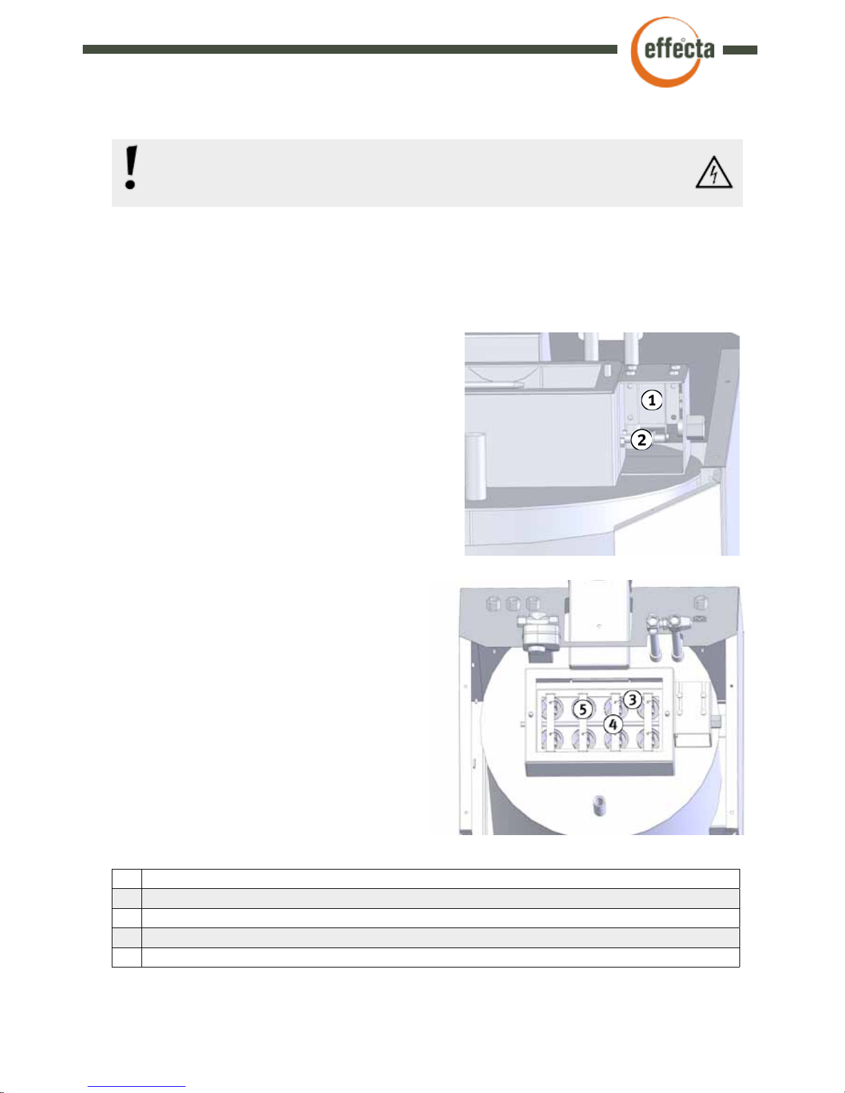
The magnet motor
The magnet motor is mounted on the right side of
the soot hatch on the top of the boiler. The magnet
motor rotates the lift shaft up and down to keep the
tubes clean.
1 Magnet motor
2 Lifting shaft
3 Flipper
4 Suspension
5 Turbulator
The turbulators
The turbulators in the tube help by reducing the flue
gas temperature and also cleaning the tubes when
pulled up and down.
▀
Cleaning system boiler
Function and service
Cut the power to the boiler before servicing. The magnet motor is mounted on the boiler to
keep the convective part clean. It is controlled from the menu ”Cleaning” on the control
panel. It can be set to work/not work in different times during the day.
Suspension
On every suspension there are two turbulators
that are removed when cleaning the tubes with
a brush.
Lifting shaft
Rotating the lift shaft lifts the turbaltors
Flipper
Flips when the magnet motor activates.
Remember to always cut the power to the boiler before starting any work on
it. All electrical work should be done by a certified electrician, for everyones
safety.
13
Effecta AB Västra Rågdalsvägen 21 434 99 Kungsbacka Sweden +46-300 - 22320 info@effecta.se
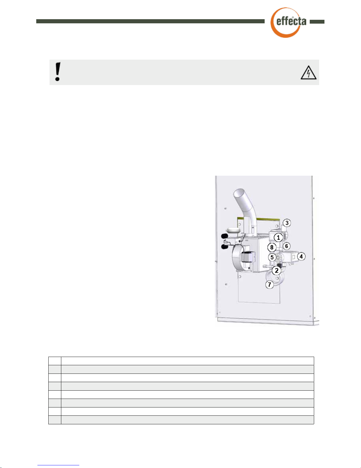
▀
Cleaning system burner
Function and service
Cut the power to the boiler before servicing. Next to the burner an air compressor is
mounted that provides pressurised air for cleaning the burner. This is done by letting high
pressure air into the burner after the burner has made a heating cycle. The compressor
builds up a pressure in the air container which is released into the burner in one blast. This
is done four times and all ash and pellet remains are blown out into the ash compartment.
The settings are made in the ”Service” menu.
The compressor
The compressor creates a pressure in the
container. The compressor has a life span of at
least 2500 hours.
Air container
The air container stores the air before it is
released into the burner.
1 Compressor
2 Solenoid
3 Silencer
4 Pressure Switch
5 Safety valve
6 Non return valve
7 Air container
8 Capacitor
The pressure gauge
Displays the pressure in the air container.
The safety valve
Prevents the pressure exceeding 9bars by releasing
air if the pressure switch fails.
The pressure switch
Stops the compressor at a pre-set value.
Normally 7 bars. This is also adjustable.
Non return valve
Keeps the air in the container and prevents
pressure on the compressor.
The cover of the burner must be screwed tight after service. Under no
circumstances should it be possible to lift it off by hand.
 Loading...