

Page 1
Rev. JG.012-01-02
INSTALLING
MAINTENANCE
SERVICE
ASSEMBLY
EFFECTA KOMPLETT
Page 2

Effecta AB Västra Rågdalsvägen 21 434 99 Kungsbacka Sweden +46-300 - 22320 info@effecta.se
2
We at Effecta would like to thank you for putting your trust in us when choosing your new
boiler. The ”Effecta Komplett” has been developed to give you maximum performance, comfort
and quality. In order to get the best results from your boiler, we suggest that you follow the
recommendations in this installation guide.
Checking your delivery
Check that the boiler has not been damaged during transportation. If the boiler has been
damaged, you must report this to the transportation company immediately.
Your safety
If you discover any faults or defects in our products, it is important that you report them as
quickly as possible to your installation engineer, so that the fault can be rectified. Make sure
that there are no flammable materials close to the boiler, to help prevent risk of fire. You must
use your own judgement when operating the pellet boiler. Remember that the hatches and some
surfaces can get hot. You must take caution to avoid being burnt.
The user
It is the user´s responsibility to operate the boiler according to our instructions. If you do not
operate and maintain your boiler correctly, the environmental impact of the boiler will be greater,
it´s efficency will be reduced and the service life of some components will be shorter. If there
is anything that you are not sure about, please contact your installation engineer or Effecta for
advice.
Warranty
The warranty takes effect from the date on which the boiler is installed. The supplied installation
form must be completed and returned to Effecta. You can find the other guarantee terms on
(page 3).
▀
Scope of delivery
Please check all components delivered.
The standard delivery as follows:
- Effecta Komplett boiler
- Cleaning handle with brush
- Rake with scraper
- Fluetube with draught stabiliser
- Turbulators, 8pcs.
- Drain cock
- Shunt valve (mounted)*
- Electrical heater 3-9 kW (mounted)
- Valve combination
- Room thermostat
- Flow sensor
- Flue gas sensor
- Boiler temp sensor
* not delivered with Effecta without coil
▀
Introduction
Page 3
3
Effecta AB Västra Rågdalsvägen 21 434 99 Kungsbacka Sweden +46-300 - 22320 info@effecta.se
▀
System data:
▀
Warranty
Installer:
Date:
Electrical installer:
Effecta products are guaranteed to be free of defects in materials and workmanship for two years
from the installation date. This applies to wear parts, such as seals, the main body of the boiler and
electrical components. This guarantee also covers original spare parts. Any faulty products will be
replaced or repaired at the discrimination of the retailer or Effecta. If a faulty product is replaced,
Effecta is entitled to replace it with a new or reconditioned product of the same or a similar type.
Effecta is liable for the costs of any servicing or repairs. Effecta gives a 5 year guarantee on the
remaining components. See the attached guarantee document.
If you have a complaint, you must contact Effecta before starting any servicing work.You must
submit your complaint without delay. You must always state the type of product, the date of
purchase and the serial number.
Otherwise the heating and plumbing industry's current regulations apply in the case of complaints.
Guarantee terms:
The guarantee is valid on condition that:
- The boiler and the heating system have been installed in accordance with the installation instructions
and in a professional manner.
- The location where the product is installed is suitable for the purpose.
The guarantee does not cover:
- The overall functioning of the heating system, costs incurred as a result of the heating system
- being out of operation or the cost of the temporary replacement of products.
- Damage or injury caused by negligence during the installation or by operating the boiler in a
way which conflicts with the installation and user instructions.
- Damage caused by abnormal wear, incorrect operation and maintenance.
- Damage caused by the boiler being positioned in an unsuitable location.
- Damage caused by vermin.
Page 4
Effecta AB Västra Rågdalsvägen 21 434 99 Kungsbacka Sweden +46-300 - 22320 info@effecta.se
4
▀
Contents
2 Introduction
2 Scope of delivery
3 Warranty
3 Terms of warranty
3 System data
4 Contents
5 In general
5 Symbols in this document
6 To the installer
7 The components
7 Exploded view, burner
8 Safety and function
9 The safety systems
10 Placement of components
11 The fuel
11 The chimney
12 Cleaning system boiler
13 Cleaning system burner
14 The mothterboard
15 1,2 or 3 Phase connection
16 Electrical connection
17 The menu system
18 The menu system
19 The menu system
20 The menu system
21 The menu system
21 Alarms at disruption
21 Ignition phase of the burner
22 First start
22 Tuning the boiler
23 Tuning the burner
24 Hot water
24 Valve combination
25 Shunt control
26 Adjustment of heating curves
27 Examples of curves
28 Mounting the auger
28 Mounting and adjusting of the draft stabilasor
29 Replacing the combustion fan
30 Servicing the flame detector
30 Overheated droptube
31 Charging the igniter
32 Cleaning the air box and outer tube
32 Mounting and adjusting of the draft stabilasor
33 Service and cleaning
34 Trouble shooting
34 The sensors
35 Documentation of settings
36 Dimensions
37 Hyudralic scheme
Page 5
5
Effecta AB Västra Rågdalsvägen 21 434 99 Kungsbacka Sweden +46-300 - 22320 info@effecta.se
The Boiler
Effecta Complete is a boiler which is to be fueled with wood pellets. No other kind of fuel is
allowed to be used. Not logs or oil.
Disassembly and disposal
It will be many years before your Effecta boiler is worn out, but it is important that you follow
the regulations in force at the time concerning disassembly and disposal of your boiler.
The fuel
The boiler should normally burn 6/8 mm fuel pellets which come either in 16 kg sacks or
are supplied by bulk truck. If you have built a bulk storage container, you should follow the
current recommendations to ensure that the quality of the pellets does not deteriorate. Never
use pellets which do not meet European pellet standards, as this may result in problems in
operating the burner.
▀
In general
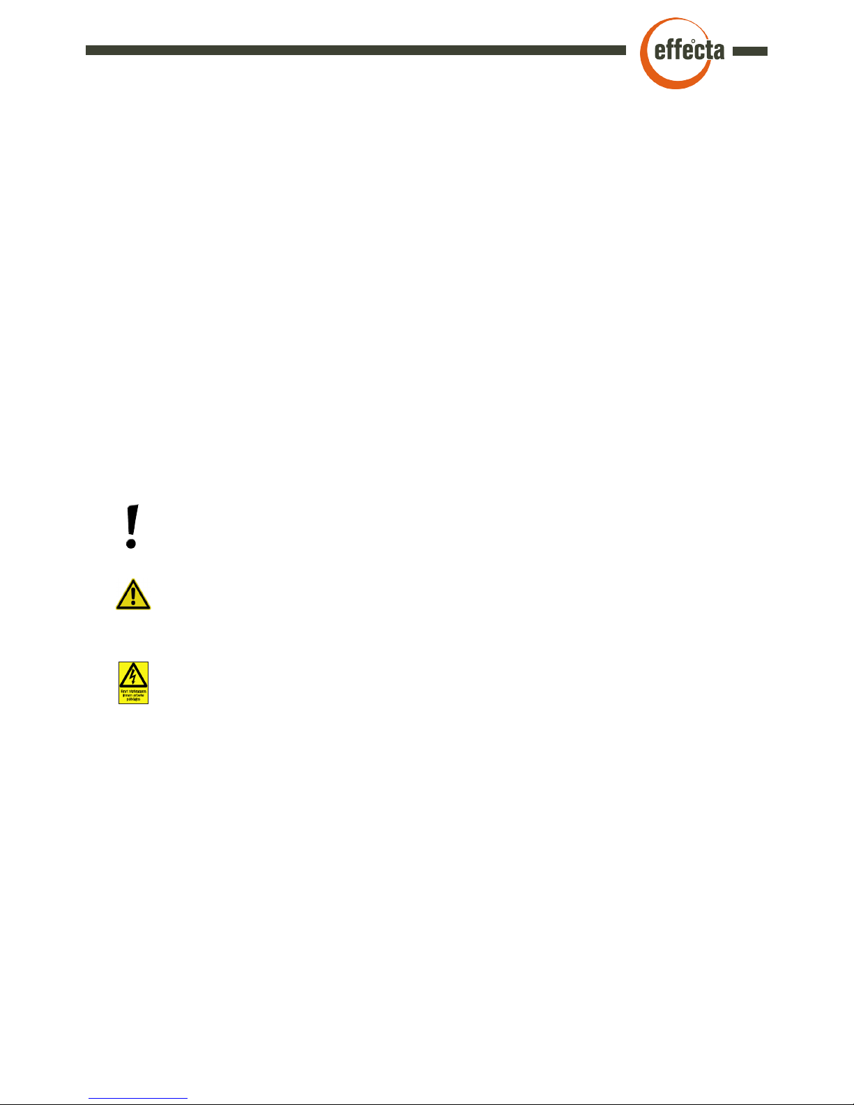
Information
This symbol is shown with info to the installer which can be important to know and
understand. Neglecting these informations can be harmful to the prestanda in the product.
▀
Symbols in this document
Warning
This symbol is shown when the installer or user must be careful in the handling of the
product. Neglecting these warnings can result in damage to the product or personal injury.
Dangerous electricity
This symbol means that extra caution should be taken. Otherwise serious personal injury
might occur. When maintaining the product where this symbol is present the power must
be disonnected. All electrical wiring must be done by a proffesional.
Page 6
Effecta AB Västra Rågdalsvägen 21 434 99 Kungsbacka Sweden +46-300 - 22320 info@effecta.se
6
▀
To the installer
It is time to install the Effecta Komplett pellet boiler. Please follow the examples we provide for
a safe installation. After installation, be sure to instruct the customer on how the heating system
and the boiler work, in order to avoid unnecessary complications in the future.
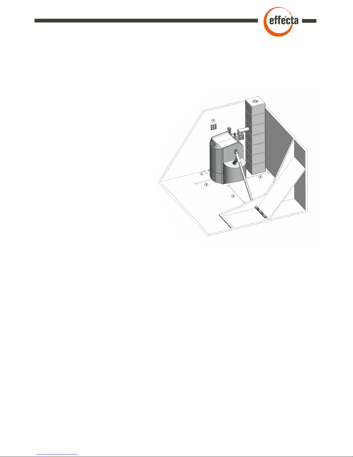
Set up
The boiler is positioned so that the surface
temperature of flammable building material does
not exceed 80°C. The boiler should be positioned
at least 15 cm (1) from the wall. The distance
from the smoke valve to a flammable wall with
ignition protective covering must be at least
30 cm (4). In order to clean the boiler, a
minimum clear space of 1 metre (2) is
required in front of the boiler and on
the side at the convection section and
at any inspection panel in the chimney.
A passage with a minimum width of 0.5
(3) m is required along one of the long
sides of the boiler. The pellet hopper
aint alowed to stand closer than 120 cm
from the boiler.
The boiler room
The boiler must be installed in a boiler room or
boiler house. The ceilings and walls must be fitted
with ignition protective covering and the floor must
be made of non-combustible material. Minimum ceiling
height at the boiler is 2 metres. The boiler room or boiler house must be equipped with a fresh air
intake with the minimum dimensions 150 x 150 (5.) mm or with a sufficiently large free sectional
area to avoid low pressure in the boiler room. It must be impossible to close the air intake.
Chimney
The chimney should have a diameter of at least 120 mm. If your chimney is smaller, Effecta
should be consulted before installation. The draught in the chimney should be about 15 pa at
low temperatures. It is important that the chimney is tested and approved by a certified chimney
sweep before a new boiler is installed. If the chimney has a strong draught, a draught controller
(see page 32) may need to be installed for good boiler operation. If you have a tall chimney and
an outgoing flue gas temperature below 170°C, there is a risk of condensation in the chimney,
which can damage the chimney in the long term. A suitable temperature is 70-80°C one metre
down into the chimney. Ask your local chimney sweep for help to measure the temperature. If the
chimney is tall and has a large area, a draught that is too strong may mean high levels of flue gas
and overignition in the firebox. If this is the case, a draft stabiliser must be installed.
Page 7
7
Effecta AB Västra Rågdalsvägen 21 434 99 Kungsbacka Sweden +46-300 - 22320 info@effecta.se
The shunt valve
The shunt valve controls the heat supply from the boiler to the radiator circuit. Effecta Complete
is fitted with motorised shunt control. The room temperature can be adjusted on a scale on the
thermostat. An automatic system will significantly reduce fuel consumption and provide a more
comfortable environment.
The valve combination
The mixing valve is used to ensure that the temperature of the hot water in your shower and
elsewhere in the house is comfortable. Set the system to the temperature you want by turning
the thermostat between +/-.
The burner
The burner is mounted on the left or right side. The burner heats the water in the boiler which
provides heat to the domestic and hot water.
The turbulators
In the tubes in the convective part hangs the turbulators. The turbulator`s function is to reduce
the heat in the flue gases on behalf of the temperature in the boiler. They must always be fitted
in the boiler. If the flue gas temperature should be to low, the turbulators can be cut off. Always
contact the installer before doing this.
The sealings
The seals on the hatches must be checked every year. If the hatches do not seal properly, the
efficiency and the combustion process of the boiler will deteriorate.
▀
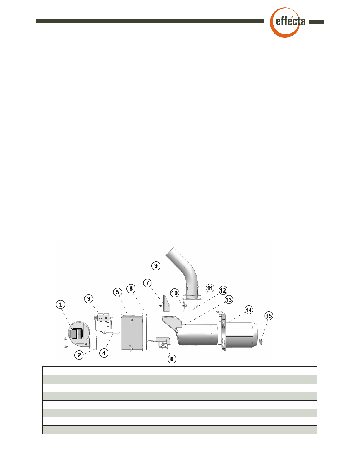
The components
1. Combustion fan 9. Feeding tube
2. Fan seal 10. Overheating protection
3. Electrical console 11. Seal feeding tube
4. Flame detector 12. Pellet retarder
5. Rear housing 13. Inner tube
6. Rear housing seal 14. Outer tube
7. Cover overheating protection 15. Stop plate
8. Ignition console
▀
Exploded view, burner
Page 8

Effecta AB Västra Rågdalsvägen 21 434 99 Kungsbacka Sweden +46-300 - 22320 info@effecta.se
8
▀
Safety and function
Before using the product, the owner and/or other user must read and understand the content in
this manual. The directions must be followed. This is to make sure that the product is functioning
correctly and accidents and injuries are avoided. Incorrect use or incorrectly tuning can result in
damages to property and personal injury or lacking function in the product. The boiler room where
the product is installed, the chimney and other components must be approved according to current
legislations.
The commisioning of the product must be made by a proffesional, according to Effectas directions
and current legislations. Controls and tuning of the product should be made by a proffesional.
A chimney sweeper should also be contacted when commisioning the product. The electrical
connections must be done by a professional, according to Effectas instructions in this manual.
The casing outside of the burner must always be fitted on the boiler when the boiler is connected to
the electrical power. Before cleaning and maintenance of the product, make sure it is disconnected
from the power line.
It is strictly forbidden to open any doors when the burner is igniting. If any door or hatch is opened
when the burner is running, great caution must be taken. Any kind of interferance or using of other
than original spare parts can result in damage to the product or person. It also removes Effecta
from any liability.
This manual should be kept during the whole life span of the product. Any updates will be reported
on the Effecta web page: www.effecta.se.
Page 9

9
Effecta AB Västra Rågdalsvägen 21 434 99 Kungsbacka Sweden +46-300 - 22320 info@effecta.se
The flexi pipe between burner and auger
The flexi pipe prevents any fire coming in to the hopper. It is made from a heat sensitive material
which melts if it gets to hot. If replaced, a new must be ordered from Effecta.
The overheating protection on the feeding tube
It stops the feeding if the fan temperatures gets to high. Reset is made manually.The cover must
always be in place when connected to main power.
Flame sensor
The flame sensor monitors the fire in the burner. If light is missing for a set time during fire the
burner stops and goes into cooling phase.
Overheating protection on the boiler
There is an overheating protection on the boiler which cuts the power to both the boiler and the
burner if the temperature in the boiler exceeds 95°C.
Compressed air cleaning system
In this cleaning system there are three different safety devices.
1. The motherboard controls the time the compressor can run.
2. There is a pressure switch that stops the compressor at a preset pressure.
3. A safety valve wich releases air if pressure exceeds 9bars.
Power outage
After a power outage the control system remembers where in the sequence the burner was. If it
was in the ”Run” mode, the fan blows for four minutes to burn out any pellet rests. Then it goes
into normal mode.
▀
The safety systems
Page 10
Effecta AB Västra Rågdalsvägen 21 434 99 Kungsbacka Sweden +46-300 - 22320 info@effecta.se
10
▀
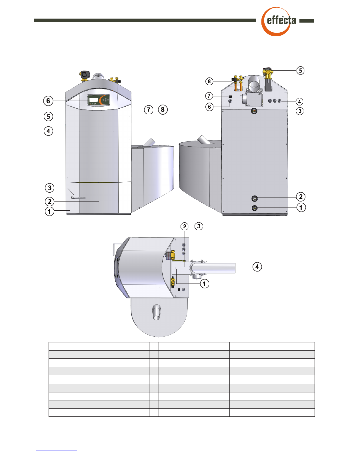
Placement of the components
Front Back Topp
1 Adjustable feet 1 Drain tap 1/2” 1 Hole for measuring instruments
2 Soot door 2 Return hot water circuit 1” 2 Sootdoor flue pipe
3 Handle soot door 3 Flow hot water circuit 1” 3 Sootdoor 3 pc.
4 Cover plate electricity 4 Hoses electrical wiring 4 Flue pipe
5 Over heat protection (behind front) 5 Shunt valve
6 Display 6 Hose for sensor
7 Feeding tube pelletburner 7 Connector feedmotor/auger
8 Protective cover 8 Mixing valve
Page 11

11
Effecta AB Västra Rågdalsvägen 21 434 99 Kungsbacka Sweden +46-300 - 22320 info@effecta.se
Wood pellet is made by sawdust, a byproduct from from handling woods. Wood contains lignin
that makes the pellet hard without any glue or other binder used.
On the market there are several different kinds of pellet. The quality and energy can be different
between them. The diameter is 6 or 8mm, the normal length is between 5 and 30mm. Pellet with
high quality has a density of 600-750 kg/m3. The moist content is 5-9% in weight.
Oil has an energy content of 9,9kW/kg and wood logs about 4,0kW/kg. Wood pellet has 4,75,0kW/kg in energy content. To maintain a good combustion the pellet should be stored in a
dry place and be protected from dirt. Pellet is delivered in sacks with 16kg content or in bulk by
truck.
Effecta Complete can handle most of the different types of wood pellet that is 6-8mm. The quality
should meet european standards. Good pellet with small amount of dust and an even quality
helps to reach good combustion, less maintenance of the product and also less environmentally
harmful emissions.
The worse quality of the fuel, the more cleaning and maintenance of the product.
▀
The fuel
The amount of pellet fed into the burner should be controlled every time the pellet brand or quality is changed. If the deviation is more than 0,5kg/hour compared to the numbers in the ”Warranty and Installation”
paper, the burner should be tuned.
Inspection
We recommend that the local chimney sweeper inspect and give advices and guidances regarding any necessary steps needed to be taken regarding the chimney and the boilers connection
to it. Some issues needed to be considered:
Dimensions
Suitable dimensions are from about ca Ø120 to Ø160 mm for a steel construction and about
140x140 mm for a bricked. The length of the chimney should be so that a draft of 15-20 Pa is
reached during operation.
A much larger/smaller flue might be needed to be adjusted to receive a proper draft. If a new
installation of the flue is done, the chimney manufacturer can give advice regarding the dimensioning. Generally speaking, a flue used for burning oil works for firing pellet in the same power
range. The draft stabiliser attached to the flue tube should always be used if nothing else is stated
from Effecta.
The flue gas temperature should be checked.
The temperature in the flue directly after the boiler in the flue should be about 160 - 200ºC.
With a tall and big chimney there is a risk of condensation which can lead to corrosion and/or
frost damages. To control this you can check the temperature 1 meter down from the top of the
chimney. The temperature should be at least 80ºC in the end of a burning session. Suggestions
for actions to be taken if needed is e.g. insulate the chimney or mount a steel pipe inside the
chimney. This will increase the temperature in the flues without effecting the efficeny of the boiler.
Other actions are increasing the power output of the burner or removing/cutting off turbulators.
This will however decrease the burners efficency some. The draft stabiliser helps keeping the
chimney free from condensation by ventilating it.
▀
The chimney
Page 12
Effecta AB Västra Rågdalsvägen 21 434 99 Kungsbacka Sweden +46-300 - 22320 info@effecta.se
12
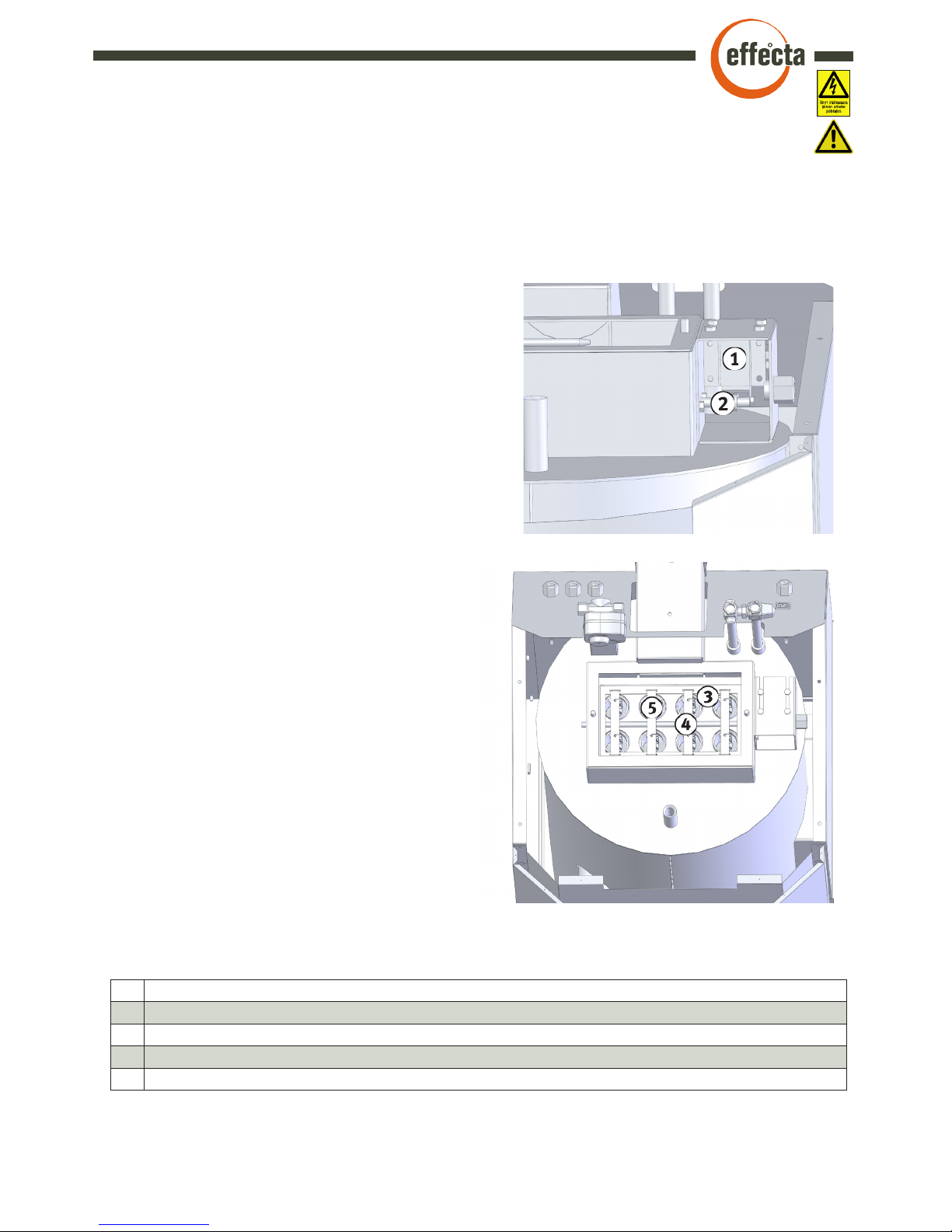
The solenoid
The solenoid is mounted on the right side of the soot
hatch on the top of the boiler. The solenoid flips the
turbulators up and down to keep the tubes clean.
1 Solenoid
2 Lifting shaft
3 Flipper
4 Suspension
5 Turbulator
The turbulators
The turbulators in the tube helps reducing the flue
gas temperature and also cleaning the tubes when
pulled up and down.
▀
Cleaning system boiler
Function and service
Cut the power to the boiler before servicing. The solenoid is mounted on the boiler to keep
the convective part clean. It is controlled from the menu ”Cleaning” on the control panel. It
can be set to work/not work in different times during the day.
Suspension
On every suspension there are two turbulators
that is removed when cleaning the tubes with
a brush.
Lifting shaft
The shaft is pulled up by the magnet making the
turbulators also being pulled up.
Flipper
Flips when the solenoid activates.
Page 13

13
Effecta AB Västra Rågdalsvägen 21 434 99 Kungsbacka Sweden +46-300 - 22320 info@effecta.se
▀
Cleaning system burner
Function and service
Cut the power to the boiler before servicing. Next to the burner a air compressor is mounted that provides pressurised air for cleaning the burner. This is done by letting high pressure air into the burner after the burner has made a heating cycle. The compressor build up
a pressure in the air container which is released into the burner in one blast. This is made
four times and all ashes and pellet rests are blown out into the firebox. In the menu ”Service” the settings are made.
The compressor
The compressor creates a pressure in the
container. The compressor has a life span of
at least 2500 hours. It might then need to be
serviced. Effecta provides a renovating kit.
Air container
The air container stores the air before it is
released into the burner.
1 Compressor
2 Solenoid
3 Silencer
4 Pressure Switch
5 Safety valve
6 Non return valve
7 Air container
8 Capacitor
The pressure gauge
Displays the pressure in the air container.
The safety valve
The safety valve prevents the pressure to exceed
9bars by releasing air if the pressure switch fails.
The pressure switch
It stops the compressor at a pre-set value.
Normally 7 bars. This is also adjustable.
Non return valve
Makes the air stay in the container and not putting
pressure on the compressor.
Page 14

Effecta AB Västra Rågdalsvägen 21 434 99 Kungsbacka Sweden +46-300 - 22320 info@effecta.se
14
▀
The motherboard
G1 Temp sensor boiler NTC 22 kΩ
G2 Sensor flue gas PT1000
G3 Extern control
G4
G5 Sensor accumulator tank low NTC 22 kΩ
G6 Sensor accumulator tank high NTC 22 kΩ
G7 Sensor, radiator flow NTC 22 kΩ
G8 Flame sensor
1U. Connection to display board
2U. Connection electricity board
1. Outdoor sensor
2. Outdoor sensor
3. Room sensor (6)
4. Room sensor (1)
5. Room sensor (4)
6. Not used
+ --
- --
PE Incoming Ground
N Incoming zero
Li Incoming phase 6,3 A/230 VAC
PE Ground
N Zero
11 Radiator pump 2A/230 VAC
12 Shunt motor
N Zero
13 Shunt motor 2A/230 VAC
PE Ground
N Zero
14 Solenoid valve AERO 2A/230 VAC
PE Ground
N Zero
15 Compressor 2A/ 230 VAC
PE --
N --
16 Solenoid valve tube cleaning 2A/230 VAC
N Zero
17 Loading pump 2A/230 VAC
Remember to always cut the power to the controller before starting any work on it.
All electrical work should be done by a certified electrician, for everyones safety.
Check so that the marking of the
prom is set at the correct side.
Before shifting a e-prom make sure to write down all the settings that has been done to
the boiler. This since all the changes that has been done will be lost.
While mounting the e-prom make
sure that the ”legs” isn´t damaged.
Page 15

15
Effecta AB Västra Rågdalsvägen 21 434 99 Kungsbacka Sweden +46-300 - 22320 info@effecta.se
▀
1, 2 or 3 Phase connection
EFFECTA AB
Västra Rågdalsvägen 21 - 43496 kungsbacka
Tel: 0300-22320 - Fax: 0300-22395
E-post:info@effecta.se - www.effecta.se
011-07-01
50-12-11
E.A
G8
G7
G6
G5
G4
G3
G2
G1
EL
17
N
16
N
PE
15
N
PE
14
N
PE
13
N
12
11
N
PE
L1
N
PE
M
NEUTRAL
OPEN
CLOSE
LOW VOLTAGE
HIGH VOLTAGE 230 VAC
L1 REQUIRED FOR FUNCTION
AND 3KW IMMERSER
N
Ground
6 1 4
DISPLAY CARD
CHARGE PUMP
COMPRESSOR
SHUNTMOTOR
RADIATOR PUMP
OVER HEAT PROTECTION 95 ˚C
POWER GRID 230 V
BLUE
BROWN
YELLOW/GREEN
BLUE
BROWN
YELLOW/GREEN
YELLOW/GREEN
BROWN
BLUE
EXPANSION CARD EL. HEATER
ROOM SENS.
N
L1
EL 2a EL 2b
EL 1b
EL 1a
L2
L2 OPTIONAL
PROM
M
TUBE CLEANING
M
BLUE
BROWN
YELLOW/GREEN
L3 OPTIONAL
EL 3a EL 3b
L3
51
52
53
54
55
56
57
58
AMPERE METERS
JOINT
123456+
-
OUTDOOR SENS.
RC 482
Display
YELLOW/GREEN
BROWN
BLUE
SOLENIOD VALVE
24
23
22
21
N
YELLOW/GREEN
M
FAN MOTOR
IGNITOR
O.H
PROTECTION
FALL SHAFT
EARTH CENTER SOCKET
EARTH CENTER PIN
FEEDER MOTOR
PALE BLUE
6.2.5.
4.3.1.
M
CIRCUIT DIAGRAM
EFFECTA KOMPLETT
ELECTRICAL HEATER 3+3+3 KW
N
BOILER PROBE
FLUE GAS PROBE
EXTERN CONTROL
ACC. HIGH
ACC. LOW
FLOW SENSOR
FLAME SENS.
Page 16

Effecta AB Västra Rågdalsvägen 21 434 99 Kungsbacka Sweden +46-300 - 22320 info@effecta.se
16
▀
Electrical connection
When it’s time to do the electrical connection you need to remove the front casing which
are in front of the motherboard. On the backside of the boiler there are four (1) hoses that
ends in the front of the boiler (5). Those shall be used to connect the sensors and electrical cables. Don’t put the low and high voltage in the same hose. When you remove the
front casing you unscrew the three screws that hold the
plastic panel in place (2). Don’t forget to disconnect the
cable to the display. To loosen the front cover you need
remove the upper (3) screws all the way. Then lift the
casing up.
Then connect the input voltage to the card’s ports, according to wiring diagram on previous page.
NOTE! The boiler must be filled with water before the wiring begins.
Current sensors
If you’re electrical system
have a problem to provide
enough electricity to the electrical heater and the house at
the same time you can install
current sensors that lower the
power to the electrical heater
if its necessary. This is done
by distributing the power to the
building’s different phases.
Connection of current sensors
To mesure the power you must
install one current sensor to
each incoming phase in the
house. This must be done directly in the electrical central.
Connect the sensors to a cable
with the area of 0,5mm2 to the
circuit board. In the menu “electrical heater” you set the max power that’s
allowed on the fuses in your house.
Page 17

17
Effecta AB Västra Rågdalsvägen 21 434 99 Kungsbacka Sweden +46-300 - 22320 info@effecta.se
▀
The menu system
+
‹
-
‹
Boiler temp.
Fluetemp
Status: Standby
FV
--- %f
75°C
175°C
13:17:44
Start dose
Supp. dose
Oper. dose high
Oper. dose low
Run start dose
Run supp. dose
Run oper. dose
Fill feeder
Clean at
On
Off
Interval
Number clean
Clean pause
Cleaning conv..
Fluegas
Max time burner
Ext. contr. closed / open
Quick start
Chimney fan
►
Number starts
Igniter
Oper. pellets
Clean number
Reset info
65s
10s
22%
7%
no
no
no
no
09:00
21:00
1
4
13s
3st
90°C
3h
No
Boiler temp G1
Fluegas
El.heater
Acc.tank high G6
Acc.tank Low G5
Room temp
Status: Standby
FV
--- %f
75°C
175°C
3 kW
55°C
65°C
21.5 (20.0)°C
13:17:44
►
Burner
Fan
Feeder
Temperature set
Information
Service
Installation
Off
VER: 1.10
Weekday
Time
Calibrate sensors
Function test
Alarms
English
►
Mon
00:00
►
►
55
%
10%
No
Fan highspeed
Fan lowspeed
Fan lowspeed
►
►
►
►
24 (45)
Komplett
Room sensor
Room temp
Flow.temp
Radiator pump
Max flow temp
Max room temp
Min room temp
Heating from
Outdoor temp.
Heat curve
Slope
Adjustment
Energy saver
►
06 _ _ _ _ 22
06 _ _ _ _ 22
06 _ _ _ _ 22
06 _ _ _ _ 22
06 _ _ _ _ 22
06 _ _ _ _ 22
06 _ _ _ _ 22
Lowering temp.
Mon
Tue
Wedn
Thu
Fri
Sat
Sun
- 5 °C
►
►
Both
20.0 (18.2)°C
50°C
Yes
60°C
25°C
15°C
16°C
-8°C
40°C
0
°C
Yes
- +
82
0 :00
►
System settings
Temp.El.
Shunt control
Product
El.heater
100st
10h
100h
130st
no
Ign. sequence 1
Ign. sequence 2
Ign. sequence 3
Miss ign.
Stopp start phase
Stopp oper phase
Flame sensor
Igniter
Feeder
Fan
Compersson
Solenoid valve
Test cleaning
Convection clean
Shunt motor (+/-)
El. heater
Radiator pump
Loading pump
0%
0
0
0%
0
0
0
0
0
0
0
0
►
23
12
3
0
0
2
►
Sensor T1
Sensor T2
Sensor T3
Sensor T4
Sensor T5
Sensor T6
Sensor T8
Sensor T8
►
0°C
0°C
0°C
0°C
0°C
0°C
0°C
0°C
Temp level
Temp down °C/6 min
►
20°C
5°C
6 ( 9) kW
11 (16)
0h
0h
El.heater
El. step (A-B-C)
Fuse A
Runtime 6 kW
Runtime 3 kW
Level start
Level oper
Time oper.
Time phase out
60%
25%
60s
80s
►
0s
10s
50%
180s
120s
Testblow start
Phase out
Fan pre oper.
Clean phase out
Ramp phase out
Fan ingition
Flame sensor
Quick start
►
Operation settings
System settings
Other settings
►
►
75°C
85°C
75°C
55°C
65°C
80°C
90°C
55°C
90°C
Boiler temp G1
Stop
Start
Acc.tank high G6
Acc.tank low G5
Stop G5
Max G6
Start G6
Max G1
Page 18

Effecta AB Västra Rågdalsvägen 21 434 99 Kungsbacka Sweden +46-300 - 22320 info@effecta.se
18
▀
Menu system
Current boiler temp. G1
Fluetemp
Acc. tank high G6
Acc. tank low G5
Room temp
Status
Operation settings
Boiler temp
Current temperature of the flue gases G2
Current temp of the acc. tank top. (Only shown when sensor is installed)
Current room temperature. (Only shown when installed and activated in software.)
Current burner mode. (Ignition-Running-Cooling-Standby-Off)
Settings for burner.
System setups
Settings for heating systems.
Other settings
Remaining settings.
►
►
►
El. heater
Current effect of the electrical heater in the boiler.
FV ---%
Setting of the fan speed in full effect oper. mode.
Fan lowspeed
Fan highspeed
Setting of the fan speed in low effect oper. mode.
Temperature set
►
Fan lowspeed
Low effect mode active: (YES/NO)
Fan
Temperature set
Information
Service
Installation
Burner
Feeder
Burner mode (on/off)
Settings for the fan of the burner.
Settings of the augers feeding control.
Settings for the burners operation temp.
Operations log of the burner.
Menu for burner service settings.
Settings for automatic cleaning etc.
Oper. dose high
Oper. dose low
Run start dose
Run operation dose
Fill feeder
Run supp. dose
Supp. dose
Start dose
Start dose size, measured according to (page 23).
Size of support dose, dose is given between ignition and running mode.
Size of the high effect feeding dose (page 23).
Size of the low effect feeding dose (page 23).
Test run of start dose for measuring. Only available in burner mode off.
Test run of supp. dose for measuring. Only available in burner mode off.
Test run of operation dose for measuring. Only available in burner mode off.
Activates auger feeding for 15 minutes. Only available in burner mode off.
Start
Acc.tank high G6
Acc.tank low G5
Max G6
Start G6
Stop
Boiler temp G1
Stop G5
Max G1
Shows the boiler temp, start/stop sensor with overheating function.
Temperature when the burner goes to standby mode.
Temperature when the burner starts up from standby mode.
When loading acc. tank, sensor G6 should be installed at the tank top of the
primary tank. The sensor starts the burner at set temp.
When loading acc. tank, sensor G5 should be installed low or at the bottom of
the primary tank. The sensor stops the burner at set temp.
Temperature when burner starts.
Temperature when burner stops.
Maximal allowed temperature G6, tank overheated.
Maximal allowed temperature in the boiler.
Feeder
►
Fan
►
Current temp of the acc. tank bottom. (Only shown when sensor is installed)
Current strength (brightness) of flame in boiler.
Page 19

19
Effecta AB Västra Rågdalsvägen 21 434 99 Kungsbacka Sweden +46-300 - 22320 info@effecta.se
▀
Menu system
Information
►
Oper. pellets
Clean number
Igniter
Number starts
Displays the number of burner starts been done
Displays the number of hours ignitor has been lit.
Displays the number of hours the burners been running.
Displays the number of times the AERO unit has cleaned the burner.
Reset info
Resets the information above.
Service
►
Off
Interval
On
Clean at phase out
Option if cleaning should be done prior to or after the running cycle.
Time when AERO cleaning is allowed (ON).
Time when AERO cleaning is not allowed (OFF).
Choice of how often the AERO cleaning is to be done.
Number clean
The amount of blows in a cleaning cycle.
Clean pause
Cleaning at
Max time burner
Extern control
Time between each blow in a cleaning cycle.
Temperature when flue tubes is cleaned.
Max operation time of the burner before pause with AERO cleaning.
Choice of external START/STOP control to the boiler. The control could be
done either by NC or NO connection.
Installation
►
Fan pre oper.
Clean phase out
Phase out
Testblow start
Seconds the fan blows before ignition phase. Detection of ”old” flame.
Seconds the ignitor is active after the flame sensor has approved start value.
The fan speed before operation phase.
Time that the fan afterblows before standby or cleaning.
Ramp phase out
Time that the fan decreases it´s speed after running cycle.
Quick start
►
Temp down - min
Temp down - °C
Degrees temp shall fall before burner goes to quick start.
The time in which the temp. shall fall before burner activates quick start.
Flame sens
Quick start
►
►
Flame sensor
►
Time oper
Level oper
Level start
Time phase out
Set value where the burner goes from ignition mode to operation mode.
Lowest approved value in operation mode. If lower: ”ALARM BURNER”
Time before ”ALARM BURNER” when flame sensor lower than level oper.
Time the fan goes to max speed.
Menu options for the flame sensor.
Menu options for the quick start function.
Cleaning conv..
The amount of pulls of the solenoid valve for the flue tubes.
Page 20

Effecta AB Västra Rågdalsvägen 21 434 99 Kungsbacka Sweden +46-300 - 22320 info@effecta.se
20
▀
Menu system
►
Setting of current weekday
Function test
Givare G2
Time
Calibration of each sensor +/- 4 °C
Test mode of the products different functions.
Givare G1
Calibrate sensors
Setting of current time
Option to calibrate/adjust all the sensors connected.
Other settings
Givare G3
Givare G4
Givare G5
Weekday
Alarms
Language
►
►
►
Alarm log
Choice of system language
Givare G6
Givare G7
Givare G8
Flow. temp.
Option of set value of the room temperature
Radiator pump
On/Off control of radiator pump.
Max flow temp
Maximum allowed temperature to the flow.
Energy saver
The amount of degrees to be lowered at choosen times.
El. step 3-6-9
Fuse A
El. heater 6 kW
Choose between different effects on the electrical heater. 1 phase is maximum 3kW
El. heater 3 kW
Log of runtimes of the different electrical heating steps.
Heating off
Outdoor temp when heating turns off. Rad. pump is runned 1min/2hours.
Outdoor temp
Outdoor temperature at the outdoor sensor
Heat curve
Option of slope to the heat curve (page 27).
Max room temp.
Maximum allowed room temp.
Min room temp
Minimum allowed room temp. Shunt opens full at set temp.
Min flow temp
Room temp
Minimum allowed flow temp.
Room sensor
Option of control, (ROOM, OUTDOOR or BOTH.
El. heater
Current load to the fuse in Amps.
►
Shunt control
►
Temp. to radiator/underfloor heating G7.
Slope
Adjustment
Lowering temp.
►
►
►
Option of adjustment to the heat curve (page 27).
The heating curve for the heating control (page 27).
06 _ _ _ _ 22
06 _ _ _ _ 22
Mon
Tue
Weekly schedule of lowering the indoor temp/ flow temp at choosen times. Please
note that for instance underfloor heating is slow and therefore takes time to reheat.
Options for energy saver (such as day/time/temp control.
Options for the electrical heater.
Options for the shunt control
►
Calibrate sensors
Page 21

21
Effecta AB Västra Rågdalsvägen 21 434 99 Kungsbacka Sweden +46-300 - 22320 info@effecta.se
Ignitor
Activates the auger/feeder.
Flame sensor
Feeder
Fan
Compressor
Solenoid valve
Test cleaning
Convection cleaning
Function test of the flame sensor. Must be illuminated to test function.
Activates ignitor, the fan starts at 40% to protect the ignitor.
Activates electrical heater.
Activates the fan
Activates and tests the full AERO cleaning cycle.
Activates the shunt motors open or close, +/-
Activates the radiator pump.
Stop start
Ign sequence 1
Stop operation
Registration of which ignition sequence the boiler goes to operation mode.
►
Function test
Shunt motor
Radiator pump
Loading pump
El. heater
Activates the loading pump for another unit such as Laddomat.
Activates compressor for cleaning.
Activates/opens solenoid valve for cleaning.
Activates the flue cleaning.
►
Alarms
Ign sequence 2
Ign sequence 3
If there is a failure during ignition phase alarm will show: ”ALARM IGNITION”
If there is a failure during normal operation alarm will show: ”ALARM BURNER”
▀
Alarm at disruption
Alarm
Burner
There has been a problem during operation phase. Most likely
problem is that the pellets is out. Flame sensor can also be
covered by soot.
Alarm
Ignition
The burner has missed the ignition phase, most likely problem
is poorly adjusted starting dose. Also check the ignitor in the
function test.
Alarm
Flue gas
The flue gas temperature has been above 320°C. This is a extrmely high temperature, please check that the automatic cleaning
is working (function test). Also check the flue gas sensor.
Alarm
Boiler temp.
The temperature of the boiler has been abov it´s max value. Normally this can happen from the heat after the combustion cycle.
Try to lower the stopping temeprature if the problem reoccurs.
▀
Ignition phase of the burner
The adjusted start dose is given to
the combustion chamber.The ignitor
is lit for 30 seconds. The fan ramps
in three cycles.
If the flame sensors doesn´t detect
a flame the burner gives a support
dose. The fan ramps up in three
cycles.
If the flame sensors still doesn´t
detect a flame the burner gives a
support dose. The fan ramps up in
three cycles.
If the flame sensor detects lights
the burner goes to operation
mode in seq 1.
If the flame sensor detects lights
the burner goes to operation mode
in seq 3.
If the flame sensor detects
lights the burner goes to operation mode in seq 2.
If there is no light in seq 3 ”ALARM
START” will be showm in display.
▀
Menu system
Page 22

Effecta AB Västra Rågdalsvägen 21 434 99 Kungsbacka Sweden +46-300 - 22320 info@effecta.se
22
►
▀
First start
▀
Tuning the boiler.
The boiler is only roughly set from the factory. Before first start an easier tuning must be done.
Then the boiler can be started and the combustion can be controlled and fine tuned with a flue
gas analyzer. After a couple of week in service, a check of the flue gas values should be done.
►
The values shown in the menues earlier are good for a startup of the boiler. Then
fine tuning is needed.
►
►
►
►
Start with the settings by entering the boilers menu (page 17.).
Temperature settings
The start and stop temperatures for the burner is set in the menue ”TEMPERATURE
SETT.” The start temperature should not be set below 75°C, there might be problem
with hot water running out. This is of course depending on which boiler being used.
Temperature el.heater
Set the temperature for the electrical heater to start if there would accure a fault or the
pellet should run out. Set the temperature 5-10°C below the burners start temperature.
Cleaning of tubes
Set the time when the cleaning of the tubes should be activated.
Clock
In this menu, the same as ”Cleaning”, the time is set. If there is a power outage, unfortunately the clock has to be set again.
Shunt
Set the desired indoor temperature. Do this by turning the room thermostat. There is
no value on the knob, the value is changed on the display on the boiler. The thermostat
should be placed in an open space without interferences by heat from e.g a stove or
cold draft. Sometimes the heating system might need to be trimmed by turning the thermostats on the radiators in different rooms.
El. heater
Here you set what effect the electrical heater should have if activated. You can choose
3 or 6kW, or both. If both is set to active the effect will be 9000W. Remember to check
that the fuses in the house can handle the power to the electrical heater.
Page 23

23
Effecta AB Västra Rågdalsvägen 21 434 99 Kungsbacka Sweden +46-300 - 22320 info@effecta.se
▀
Tuning the burner
►
►
►
►
►
Fill screw
Start with filling the auger by setting ”FILL SCREW”. The auger will run for 15 min. Put a
bucket under the outlet to prevent pellet from falling out. It is important that the auger is
filled properly, therefore it is a good idea to tap it with for example a rubber mallet during
the filling.
The fan
The rpm for the fan is set in the menue ”FAN”. The rpm is dependent upon the operation
dose set. For the best efficiency a flue gas analyzer should be used. We recommend
12% CO2 in the flue gases. You also choose if the low power option should be activated.
Which might be good if for example there is a small amount of water in the boiler.
Start dose
The feeding of the pellet is the most important part in the system for a good combustion
and function. Set the start dose by activating the ”RUN START DOSE”. It is important
that the start dose is correct and it should be controlled when the burner has been running
a number of hours. The amount of pellet fed when running the start dose should be about
3,5 dl. If the burner fails to start, the dose can be increased a bit, and if it smokes a lot
during startup it might be decreased a bit.
Operation dose
The operation dose is set in the menue ”RUN OPER.DOSE”. Weigh the pellet that is fed
through the auger and adjust the power according to the diagram below. Never run the
burner at a higher power than needed, it is harder to maintain best efficiency at higher
power.
Service
In this menue the settings is deciding how and when the burner should be cleaned with the
compressed air. The less time the cleaning is set to be prevented, the better. There will be
fewer times/year the burner needs to be cleaned manually if the compressor is allowed
to do the work. Here is also the maximum time set for the burner to be running before
it cleans itself. It goes into cooling phase and cleans and then startup again. When the
settings are made, set the burner to ”ON”, and the first start will take place if there is a
heating need from the boiler.
Power kW 12,5 15 17,5 20 22,5 25 27,5 30
Amount of fuel kg/h 2,6 3,1 4,7 4,1 4,7 5,2 5,7 6,25
Doses calculated with pellet with the energy content 4.8 kWh/kg.
If ”RUN OPER.DOSE” is set, the auger will feed small doses of pellet for 6 minutes in
the same way as when it is running normally. Weigh the pellet fed to get the right power. 6
minutes is equal to 1/10 of 1 hour. If you set the burner on 20 kW it should have 410 g as
operation dose.
Page 24

Effecta AB Västra Rågdalsvägen 21 434 99 Kungsbacka Sweden +46-300 - 22320 info@effecta.se
24
▀
Valve combination
The valve combination is there so the hot water temperature doesn’t get to scalding temperature. In order
to increase the temperature turn (1) against +. You
may also need to tune the flow valve (6) to reduce
the flow through the coil. There is a safety valve (9)
that releases the water out of overflow tube (10) if the
pressure in the hot water circuit is too high. Note that
overflow pipe should always have drainage to a floor
drain.
1 Temperature control 6 Flow control valve
2 Hot water 7 Mixing valve
3 Cold water 8 Vent pipe
4 Hot water out 9 Safety valve
5 Cold water in 10 Overflow pipe
▀
Hot water
Hot water is produced in a copper coil. There are flanges on the
outside on the coil for best heat absorption. The cold incoming
water is mixed with the heated water from the coil in the mixing
valve (1). The mixing valve includes a thermostat where you set
the temperature on the outgoing water. If you don’t run the boiler
with pellet there also is a possibility to heat the hot water with the
electrical heater which should be set to 70°C for good hot water
comfort. If the operating temperature of the burner or electrical
heater is too low, the coil will not deliver the quantity of hot water
as desired for larger amounts.
When hot water is prepared in a coil, legionella bacteria cannot
occur.
Page 25

25
Effecta AB Västra Rågdalsvägen 21 434 99 Kungsbacka Sweden +46-300 - 22320 info@effecta.se
Room sensor
If the room sensor is used it is recommended to be installed in a open space near the center
of the house. The sensor shouldn´t be interfered by draught, doors, sunlight directly to it or
other heat sources since it then will block the entire heating output to the house.
Loosen the control wheel by
pulling outwards. The loosen
the screw to open the box.
6 Connected to number 3 on the main board 4 Connected to number 5 on the main board
2 Not used 1 Connected to number 4 on the main board
▀
Shunt control
In the menu ”shunt control” there are different options of controls; indoor sensor, outdoor
sensor or both in combination.
Outdoor sensor
If a outdoor sensor is used this should be mounted on the facad of the house. It is important
the sensor is mounted on the north side of the house. Make sure that the sensor isn´t
disturbed from solar insolation. It is recommended that the sensor is mounted about 2 metres
from ground level and if possible protected from water and such.
1 Connected to 1 on the main board
2 Connected to 2 on the main board
Loosen the screw and split the
casing. It is then possible to
mount the box to the wall.
Page 26

Effecta AB Västra Rågdalsvägen 21 434 99 Kungsbacka Sweden +46-300 - 22320 info@effecta.se
26
▀
Adjustments of heating curves
The appropriate heating curve is essential in order to have to right indoor temperature. The
heating curve needs to be adjusted to the specific energy demands of the house it is installed
in. All houses have different demands, which could give that one house would need a 25˚C flow
at a outdoor temperature of +-0˚C while another house needs 45˚C.
Adjustment to the heating curve is done in the menu “Shunt control”. In this menu it is possible to alter both the slope and the adjustment to the curve. To find and adjust the correct
heating curve it is important that the following points are fulfilled:
- The outdoor temperature must not be higher than +5˚C
- Energy saver function must be switched off.
- Valves on the radiators must be fully open.
- Radiators must be checked and in function.
It is normal that during the first heating season changes must be done several times in order
to find the right setting for the house. When the right setting is found there is no need for any
changes for years to come. This is the greatness with an outdoor sensor. To start out with
something as a rule of thumb we could recommend these initial settings:
- Houses with underfloor heating in concrete. “Slope 35”
- Well insulated low energy house with low temp. radiators. “Slope 40”
- A high temp. radiator system in a older house with poor insulation. “slope 55”
Example of slope:
If the slope is set to 50˚C this is the temperature sent to the flow at a outdoor temperature of
-15˚C.
Example of adjustment:
When an adjustment is done to the slope this is done parallel to the curve. Meaning that if an
adjustment of 5˚C is done. This happens for the whole slope.
Page 27

27
Effecta AB Västra Rågdalsvägen 21 434 99 Kungsbacka Sweden +46-300 - 22320 info@effecta.se
▀
Example of curves
A too low heating curve will result in that the house will not have the correct indoor
temperature
-30 -25 -20 -15 -10 -5 0 5 10 15 20 25
80
70
60
50
40
30
20
Temperature flow
Slope
The heating curve chosen in the software is the temperature
to the flow at -15˚C outdoor temperature. Therefore the flow
temperature will change with the outdoor temperature.
Outdoor temperature
-30 -25 -20 -15 -10 -5 0 5 10 15 20 25
80
70
60
50
40
30
20
Outdoor temperature
Temperature flow
Adjustment
Slope 50˚C, adjustment +5˚C
Slope 50˚C with no adjustment
! If it is cold outdoors (cold winter) and the room temperature is too low. Increase the slope
with 1-2˚C
! If it is cold outdoors (cold winter) and the room temperature is too high. Decrease the
slope with 1-2˚C
! If it is warm outdoors (average autumn/spring) and the indoor temperature is too low.
Increase the adjustment with 1-2˚C
! If it is warm outdoors (average autumn/spring) and the indoor temperature is too high.
Decrease the adjustment with 1-2˚C
! Wait at least 24 hours between adjustments and changes due to slow response of heating.
When a adjustment of 5˚C is done, the heating curve is
adjusted at all outdoor temperature with 5˚C.
Page 28

Effecta AB Västra Rågdalsvägen 21 434 99 Kungsbacka Sweden +46-300 - 22320 info@effecta.se
28
▀
Mounting the auger
Ø75, 1.7 and 2.5 m, mounting in Mafa Micro, Mini or Mini Storage.
Make sure the helix spiral is 15-25 mm inside the plastic tube (1). Adjust by loosening the
clamp (2) and move the plastic tube to the correct dimensions.
Adjust the store location so that the feed screw is properly positioned over the burner, with
a tilt of between 30 - 45 °. Mount a hook in the ceiling above the auger for hanging it in the
strap. (min. Ø6, not included).
Insert the auger into the store pipe, it shall rest entirely on the store lid (3). Secure Mafa
storage lid with 2 short screws (4), alt. used a hose clamp (5) as a stop. Hang the auger on
the hook with the strap. Install appropriate flexi hose and make the final adjustment to the
burner. Move the screw and the storage so that the hose reduction can be pressed in to the
drop pipe. The tube should not be stretched or squashed.
Check inside the store that the auger intake is completely visible. Adjust, if necessary, by
loosening the clamp (2) and rotate the plastic tube to the correct position. First select the
pipe location in the longitudinal direction so that the former adjustment does not change.
Make sure the clamp is applied and tightened before the auger is in operation. Connect the
power cable to the burners connector.
The spiral must stay just outside or in line with
the tube (not adjustable). Insert the auger 420
mm of the store pipes, mount hose clamps (5)
to stop. Check inside the store that the auger
intake is completely visible. Adjust and hang up
as described for Ø75 feed screw.
Install the screw engine in the flange of the screw.
The M8-screw with distance tube should stay in
the motor plate to lock the motor from rotating.
Be sure the locking screw in flange is in the
groove on the motor shaft and tighten. Connect
the power cable to the burner.
Ø90 steel, 1.7 and 2.3 m, mounting in Mafa Micro, Mini or Mini Storage.
Page 29

29
Effecta AB Västra Rågdalsvägen 21 434 99 Kungsbacka Sweden +46-300 - 22320 info@effecta.se
▀
Replacing the combustion fan
When a fan has been replaced, a new analyze of the flue gas should be done. The RPM
can vary between fans.
Disconnect the power supply to the boiler. Loosen the three wing nuts and lift the cover up.
Disconnect the power supply to the burner. Loosen the power cable to the burner, cable to the
flame sensor and the air supply if its connected. (let the ignition element stay remain in the
ignition device). Note the electrical routing and attachment of all cables.
Disconnect power leads from the fan by pulling out the pins (1). Remove the four screws (screw
3 mm) and remove the fan (2). Install the new fan. Make sure the conduit to the ignition element
cable, is in place.
Replace the ignition device according to the ”change of ignition elements.” Attach the wires
to the igniter and thermal protection and flame sensor with cable ties in the mounting bracket.
Page 30

Effecta AB Västra Rågdalsvägen 21 434 99 Kungsbacka Sweden +46-300 - 22320 info@effecta.se
30
▀
Changing and/or servicing the flame detector
It is important that the cables are connected the same way to burner as they were, otherwise it will display 100% light all the time and the burner will be faulty.
Disconnect the power supply to the boiler.
Loosen the three wing nuts and lift the cover
up. Note how the flame sensors are coated
and remove the cable tie from the mounting
bracket. Disconnect the terminal block of the
flame sensor (1) by pulling it straight back.
Then loosen the burner from the outer tube by
loosening the four wing nuts (2) Then loosen the
nut that holds the flame sensor in place inside
the house. Then take the flame sensor out and
replace with the new. Reassemble in reverse
order. When cleaning the flame sensor, use a
damp cloth after you loosened the burner from
the burner tube.
▀
Overheated feeder tube
On the feeder tube of the pellet burner there is a heat protection. This turns out to protect against backfires. If the protection tripped, the voltage disappear to the auger. The cause of
overheating is usually due to large back pressure in the boiler,
which in turn usually depends on:
- Burner tube is full of soot.
- The boiler is full of soot.
- The chimney is too narrow.
- The burner is set to high power.
Reset the protection by loosen the bracket wich is placed in
front of the overheating protection (1). Then press the reset
button (2) and you will hear a click when it is restored.
If the protection is activated again, we recommend that you
contact your installer to review the function and settings.
Page 31

31
Effecta AB Västra Rågdalsvägen 21 434 99 Kungsbacka Sweden +46-300 - 22320 info@effecta.se
▀
Changing the igniter.
Disconnect the power supply to the boiler. Loosen the three wing nuts and lift the cover up.
Loosen the power cable of the burner, the cable to the flame sensor and the air supply. (1)
Remove the four bolts (2) wich are holding the burner housing against the end plate of the
mantle. Angle the burner housing and pull it upwards/backwards so that the feeder tube loosens
from the burner. Then detach the pipe to purging by unscrewing the quick connector on the
outside of the rear housing. Then disconnect the ignition element wires on the terminal block
located under the metal lid of the connection box (3). Remove the ignition device from the rear
housing (two screws on the bottom of the burner (4). Ignition element cap is removed (5) and
the element is pulled out of the square tube.
Slide the new element in the square tube. Push to lie on the outer edge of the square tube (6).
Install the clamp and tighten the screws with moderate force, so that the element is not going
to fly back and forth.
Insert the ignition device in the rear housing. The cables should be pulled out through the fan’s
cable access. Connect the cables on the terminal. Secure the two cables to each other with
a cable tie. Reassemble in reverse order, wait to fasten ignition device in the burner until the
burner is mounted together with the mantle. Push the ignition device to the burner tube and
tighten the two bolts. Check that the square tube is in the middle of the hole in the burner tube.
When you re-mount bracket for
ignition element and compressed
air pipe, you must be careful
that it is pushed as far forward
as possible to the burner tube.
If there is a gap in between can
ignition of the pellet be difficult
and cleaning impaired.
Page 32

Effecta AB Västra Rågdalsvägen 21 434 99 Kungsbacka Sweden +46-300 - 22320 info@effecta.se
32
▀
Cleaning the rear housing and outer tube
After a period of heating up, there will be dust and soot from the burner´s
inner and outertube. These must be removed to avoid deterioration
in combustion and function. We recommend that the cleaning is
done after about 6 tons of pellets consumption. After the cover
is removed, start by loosening the
four wing nuts (1) wich are holding
the burner in place and then unload
according to description. Then pull
out the inner tube (2) and clean
from ash and soot. It is important
that the holes are not clogged with
soot, as these are essential to good
combustion. Then clean the outer
tube (3) from the soot and pellet
residues. Reassemble in reverse
order.
▀
Mounting and adjusting of the draft stabiliser.
A draft stabiliser makes sure that a constant and stable draft is achieved. Also condensation
in the chimney is avoided.
Adjusting the balancing shaft
To adjust this shaft, loosen the two screws a bit and turn the shaft so that it is horisontally when
the hatch is closed. Then fasten the screws.
Adjusting the draft
By moving the counterweight along the balanceshaft, the draft needed to open the hatch is
adjusted. About 1Pa per 2mm.(fig.2) The hatch is preset at about 1Pa. A professional should
measure the draft and make the adjustments.
Functions
Tigex draft stabiliser opens the hatch just as much as needed depending on the current draft.
The draft varies a lot depending on the chimney, weather and also if the burner is running or
not. This means that the hatch can be open alot, a little or closed, depending the situation.
Page 33

33
Effecta AB Västra Rågdalsvägen 21 434 99 Kungsbacka Sweden +46-300 - 22320 info@effecta.se
▀
Service and cleaning
Cut the power to the boiler before starting the service. We recommend a good service/cleaning
of the burner and boiler 2-3 times a year. Do as follows for best result and minimizing the
chances for failures.
Sweeping range
1. Firepbox, if necessary, or at about 3 tons of pel lets consumption.
2. Burner tubes after 3 tons of pellets consumption.
3. Convection part 3 tons of pellets consumption.
3. Without automatic cleaning every other week in
winter.
4. Soot box if necessary.
5. Smoke box after 3 tons of pellets consumption.
6. Flue pipe after 3 tons of pellets consumption.
7. The burner’s outer tube 6 tons of pellets con sumption.
8. Flame detector after 6 tons of pellets consumption
(page 30)
Cleaning the firebox
Cleaning the firebox is done through the ash door on the front. The easiest way is to use some type
of ash cleaner. If you do not have access to a an ash cleaner, remove the ash with a scrape and keep
it in a fireproof bin. Remember that ashes can contain hot particles for a long time and may not be
stored near flammable materials.
Cleaning the burner
Remove the ash contained in the burner tube, this is done either through the firepbox with the supplied
scraper or by taking the burner tubes apart outside the boiler, which sometimes can be the easiest
way.
Cleaning of convection
Cleaning of the tubes is done with the included brush, lifting the turbulators acc. (page 12). It is
important for the efficiency that these are cleaned thoroughly at the service.
Cleaning of ash and flue
Soot box, which is placed above the tubes must be emptied of ash, if the soot box is full, the flue gas
has no place to escape out through the chimney and you will receive a disruption. Also clean the flue
tube that goes to the chimney, when it is not certain that the chimney sweep do it.
The burner’s outer / innertube
The space between the outer - inner tube must be cleaned out of dust and particles after about 6 tons
of pellets consumption (page 32)
Page 34

Effecta AB Västra Rågdalsvägen 21 434 99 Kungsbacka Sweden +46-300 - 22320 info@effecta.se
34
▀
Trouble shooting
The burner does not ignite - Incorrect start dose
- Igniter faulty
- Igniter console poorly attached
- Inner tube filled with ashes
- Adjust start dose
- Replace igniter
- Adjust the console
- Clean the burner
The burner ”puffs” at start - Incorrect start dose - Adjust start dose
High temp protection on
feeding tube activated
- Low draft
- Inner tube filled with ashes
- Control the draft
- Clean the burner
Inner tube fills up with ashes - Poor combustion
- The burner cleaning malfunctioning
- Contact your installer
- Contact your installer
Ashes are totally black - Poor combustion - Contact your installer
Poor hot water capacity - Low temperature in the boiler
- To high flow in the pipes
- Set the burners ”Stop” temperature higher
- Adjust the flow on the mixing valve
- Changing the water tap
Low/high indoor temperature - Incorrect set thermostat
- Sensor untrimmed
- Placement of thermostat in a bad place
- Adjust thermostat
- Trim sensor (page17)
- Move the sensor to a better place
Soot in the boiler room - Leaking seals - Contact your installer
Alarm (flue gas) - Sooty boiler
- Poor combustion
- Broken sensor
- Clean the boiler
- Contact your installer
- Contact your installer
No heat on radiators - Shunt motor broken
- Thermostat set to low
- Contact your installer
- Adjust thermostat
White smoke from the chimney - Low flue gas temperature
- To big chimney
- Rain water in the chimney
- Cut turbulators/increase power
- Contact a professional
- Mount a rain hood
Fault Cause Action
There are actions that the end user can take to fix a stop. However, a professional should always be
adviced before doing any adjustments.
-10°C 960 ohm 60°C 1232 ohm
0°C 1000 ohm 70°C 1271 ohm
10°C 1039 ohm 80°C 1309 ohm
20°C 1077 ohm 90°C 1347 ohm
30°C 1116 ohm 100°C 1385 ohm
40°C 1155 ohm 120°C 1461 ohm
50°C 1194 ohm 140°C 1535 ohm
If the cables are lengthened, use these cables:
- For a length up to 15m 2 x 0,5m²
- For a length up to 50m 2 x 0,75m²
- Do not place these cables together with main cables(high voltage).
The value of the resistance on the Pt1000 sensors is measured with ohm meter. Disconnect the
sensor from the motherboard in order to measure. Remember that the sensors need good connection in order to get a correct result.
▀
The sensors
Page 35

35
Effecta AB Västra Rågdalsvägen 21 434 99 Kungsbacka Sweden +46-300 - 22320 info@effecta.se
▀
Documentation of settings
Before you commision the boiler system we ask you to fill out the different values set in the menues.
This is important for the future services and makes it easier in the communication between the
customer and the installer and between the installer and Effecta.
Parameters Value
Start temperature burner
Stop temperature burner
Fan speed
Temperature electrical heater
Power electrical heater
Operation dose
Start dose
Flame sensor start
Flame sensor running
Acc.tank high G6
Acc.tank low G5
Stopp G5
Max G6
Start G6
Max G1
Settings in buffer system
Parameters Value
CO2 content
CO (ppm)
Flue gas temperature
Negative pressure in the flue (pa)
Prestanda
Parameters Value
Basic settings
2011 2012 2013 2014 2015
Tillverknings år. / Manufacturing year
Tillverkare / Manufactory
Hersteller / Fabricants
Modell / Model
Typ / Modéle
Godkänd enl. / Approved by
Zugelassen nach / Approuvé á
Miljöklass / Emission class
Emissionsklasse / Classe d’émission
Max drifttemp. / Max temp. (C)
Max. Betriebstemp. / Temp d’opération max
Elinstallation / Electrical supply
Strom / Branchement électrique (VAC)
El-patron / Electrical heater (kW)
El-Patrone / El-cartouche
Vattenvolym / Water volume
Wasserinhalt / Contenance d`eau (litre)
Tillverknings nr / Manufacturing number
Herstell Nr / Numéro de fabrication
Effecta Energy Solutions AB
Effecta Komplett
EN-303-5
3
100
230/380~50Hz
3 - 9
183
Effecta AB - Sweden - Kungsbacka - www.effecta.se
Max drifttryck / Max pressure
Max Betriebsdruck / Pression maximum (bar)
1,5
Tillverknings månad / Manufacturing month
1 2 3 4 5 6 7 8 9 10 11 12
Effekt / Heat output
Heizleistung /Puissance nominale (kW)
20 30
The label is placed on the outer casing on the burner. Here
you can see the production number, month and year.
▀
Type plate
Page 36

Effecta AB Västra Rågdalsvägen 21 434 99 Kungsbacka Sweden +46-300 - 22320 info@effecta.se
36
▀
Dimensions
EFFECTA KOMPLETT 20 KW
EFFECTA AB
Västra Rågdalsvägen 21 - 43496 kungsbacka
Tel: 0300-22320 - Fax: 0300-22395
E-post:info@effecta.se - www.effecta.se
011-12-15
V50-04-47
E.A
TECHNICAL DATA
1. FLOW HOT WATER 1”
2. RETURN HOT WATER 1”
3. DRAIN COCK 1/2”
EXPLANATIONS
Width
Depth incl. smoke pipe
Height
Weight
Maximum pressure
Flue tube angle (extra)
Flue tube diameter
Floor to cc smoke pipe
Water Volume
Recommended draft
Min. schimney area
Electrical connection
Sheet thickness mantle
Sheet thickness grate
Firebox volyme
Firebox depth
Power max
Max operating temperature
1075 mm
1050 mm
1450 mm
295 kg
1,5 bar
120 mm
180 mm
1430 mm
183 liter
15 pa.
120 mm
230/380 VAC
4 mm
4 mm
106 liter
500 mm
20 kW
99 gr
Page 37

37
Effecta AB Västra Rågdalsvägen 21 434 99 Kungsbacka Sweden +46-300 - 22320 info@effecta.se
PRINCIPAL SCHEME
EFFECTA KOMPLETT WITH HOT WATER CURCUIT
AND RADIATOR.
EFFECTA AB
Västra Rågdalsvägen 21 - 43496 kungsbacka
Tel: 0300-22320 - Fax: 0300-22395
E-post:info@effecta.se - www.effecta.se
010-12-13
V50-05-56
E.A
COMPONENTS
8.
1. ROOM THERMOSTAT
2. RADIATOR VALVE
3. RADIATOR PUMP
4. REFILL
5. SHUNT WITH SHUNTMOTOR
6. MIXING VALVE
7. EXPANSION VESSEL WITH SAFETY VALVE 1,5 BAR
8. DRAIN COCK
9. DIRT FILTER
HEAT CURCUIT
3.
7.
Domestic water
6.
9.
4.
5.
2.
1.
2.
COLD WATER
HOT WATER
▀
Hyudralic scheme
Page 38

 Loading...