

Efel STANFORD 80, STANFORD 140, HARMONY I, HARMONY III Installation, Operating And Maintenance Instructions
395823110a 1
STANFORD 80 STANFORD 140
HARMONY I HARMONY III
WOOD STOVES
INSTALLATION, OPERATING AND MAINTENANCE INSTRUCTIONS
Manufactured by:
Thermic Distribution Europe SA
5 Rue du Lion
B-5660 Couvin, Belgium
SAVE THESE INSTRUCTIONS FOR FUTURE USE AND REFERENCE
Please read this entire manual before you install and use your new room heater.
Failure to follow instructions may result in property damage or bodily injury.
395823110a 3
SAFETY NOTICE
The authority having jurisdiction (such as municipal building department, fire
department, fire prevention bureau, etc.) should be consulted before installation to
determine the need to obtain a permit.
If your Efel Stove is not properly installed, a house fire may result. For your
safety, follow the installation directions. Contact local building or fire officials
about restrictions and installation requirements in your area.
ENSURE THAT THIS MANUAL REMAINS WITH THE APPLIANCE AND IS
PASSED ON TO THE USER AFTER INSTALLATION.
DO NOT STORE OR USE GASOLINE OR OTHER FLAMMABLE VAPOURS AND
LIQUIDS IN THE VICINITY OF THIS OR ANY OTHER APPLIANCE.
WARNING:
Improper installation, adjustment, alteration, service or maintenance can cause
injury or property damage. Refer to this manual for assistance or consult a
qualified (experienced) installer.
SPECIAL NOTE:
Crazing of Porcelain Enamel:
Porcelain enamel, when heated to high temperature, is subject to crazing. Crazing is
a normal occurrence when enamel is exposed to high temperatures. Your enamel
finish will not be harmed nor will the function of the stove be impaired.
SPECIAL NOTE:
A barometric damper is recommended for installations of stoves in areas that may
have high winds, which can affect the draft. The installation must be only in units
with a newly constructed chimney, free of creosote deposits. The barometric damper
is an automatic device designed to regulate the draft in a heating appliance, which in
turn, stabilizes the chimney temperatures, lessening the potential of over-firing. Do
not place the barometric damper greater than 24 inches (610 mm) above the unit.
Excessive draft will lead to poor control of the burning rate and possible over-firing of
the stove and damage to the cast iron firebox. Most barometric dampers are
calibrated in inches of water column and can be set to draft requirements of -.03 to .08 inches (-7.5 to -20 Pa). It is recommended that the barometric dampers to be set
between -.05 and -.06 inches.
THE RECOMMENDED DRAFT REQUIREMENTS FOR EFEL STOVES IS NO LESS
THAN -.04 AND NO GREATER THAN -.08.
OPERATION OF YOUR STOVE WITH A DRAFT GREATER THAN -.08 CAN
POSSIBLY CAUSE DAMAGE TO THE STOVE AND VOID THE WARRANTY.

395823110a 4
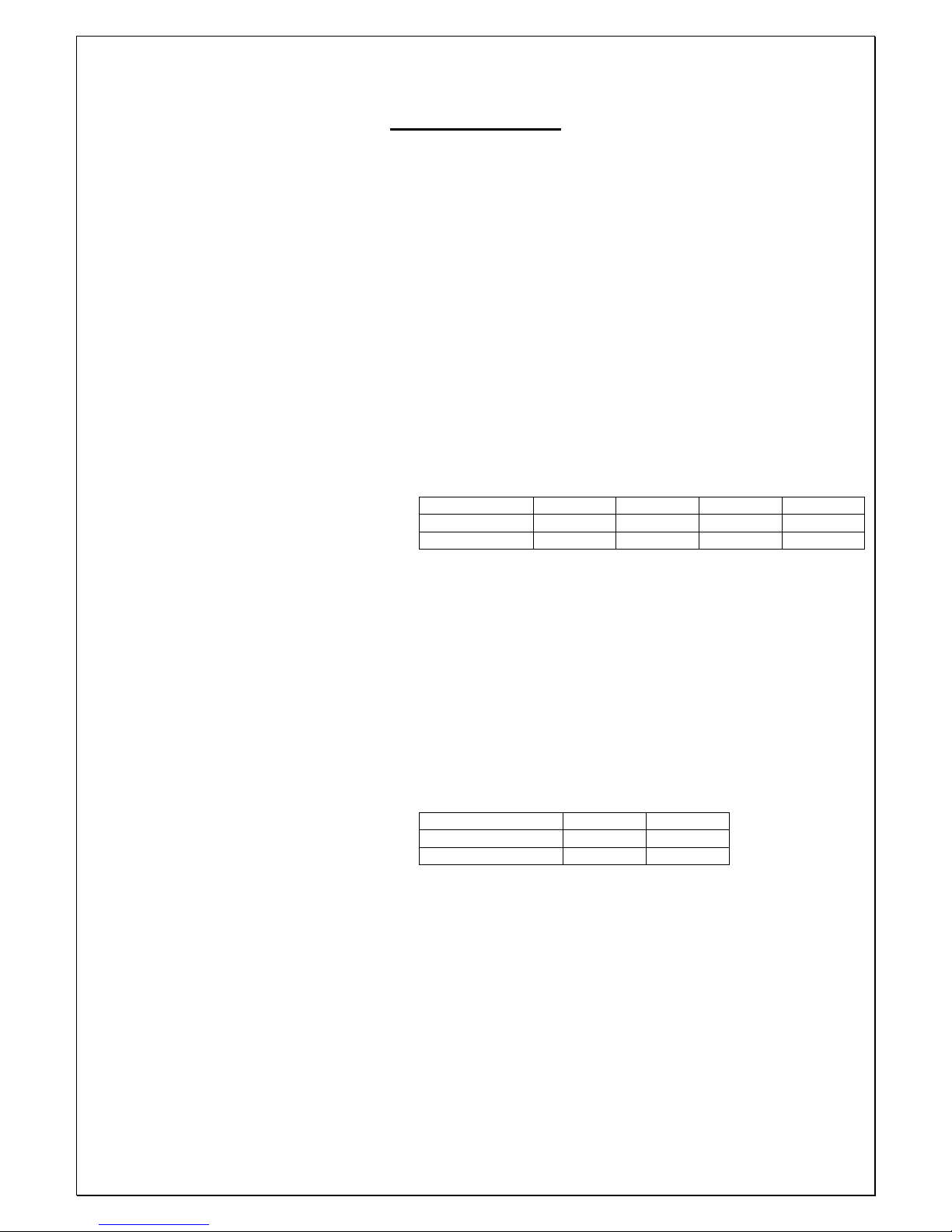
PRODUCT SPECIFICATIONS
Stanford 80 & Harmony I Stanford 140 & Harmony III
Flue collar size: 6” Flue collar size: 6”
Flue position: top Flue position: top
Max. burn rate: 87,000 BTU/hr Max burn rate: 96,600 BTU/hr
EPA Output range: EPA Output range:
11,500–55,000 BTU/hr 12,000–60,900 BTU/hr
Particulate emissions: 4.42 g/hr Particulate emissions: 2.72 g/hr
Heating capacity: 1300-1800 sq ft Heating capacity: 1800-2500 sq ft
Max. burn time: up to 8 hours Max. burn time: up to10 hours
Max. log length: 18” Max log length: 22”
Loading: front and side Loading: front and side
Weight: 303 lbs. Weight: 386 lbs.
Testing / Listing
Your Efel wood stove has been tested to UL Standard 1482 by OMNI-Test
Laboratories, Inc., Beaverton, Oregon.
EPA Certification
The Efel wood stoves have been tested to rigorous emissions standards,
and have been certified by the Environmental Protection Agency.
WARNING:
• DO NOT CONNECT THIS UNIT TO A CHIMNEY FLUE SERVING
ANOTHER APPLIANCE.
• UNIT MUST BE INSTALLED ACCORDING TO ALL LOCAL CODES.
A BUILDING PERMIT MUST BE OBTAINED BEFORE INSTALLING.
• SAVE THESE INSTRUCTIONS FOR FUTURE REFERENCE.
• DO NOT INSTALL IN A MOBILE HOME.
• READ ALL INSTRUCTIONS CAREFULLY BEFORE STARTING THE
INSTALLATION.
• UNIT MUST BE PROPERLY INSTALLED OR LISTING WILL BE
VOID.
• INSTALLATIONS OTHER THAN THOSE SPECIFICALLY COVERED
HEREIN HAVE NOT BEEN CONFIRMED BY TEST AND ARE NOT
COVERED BY THE LISTING.
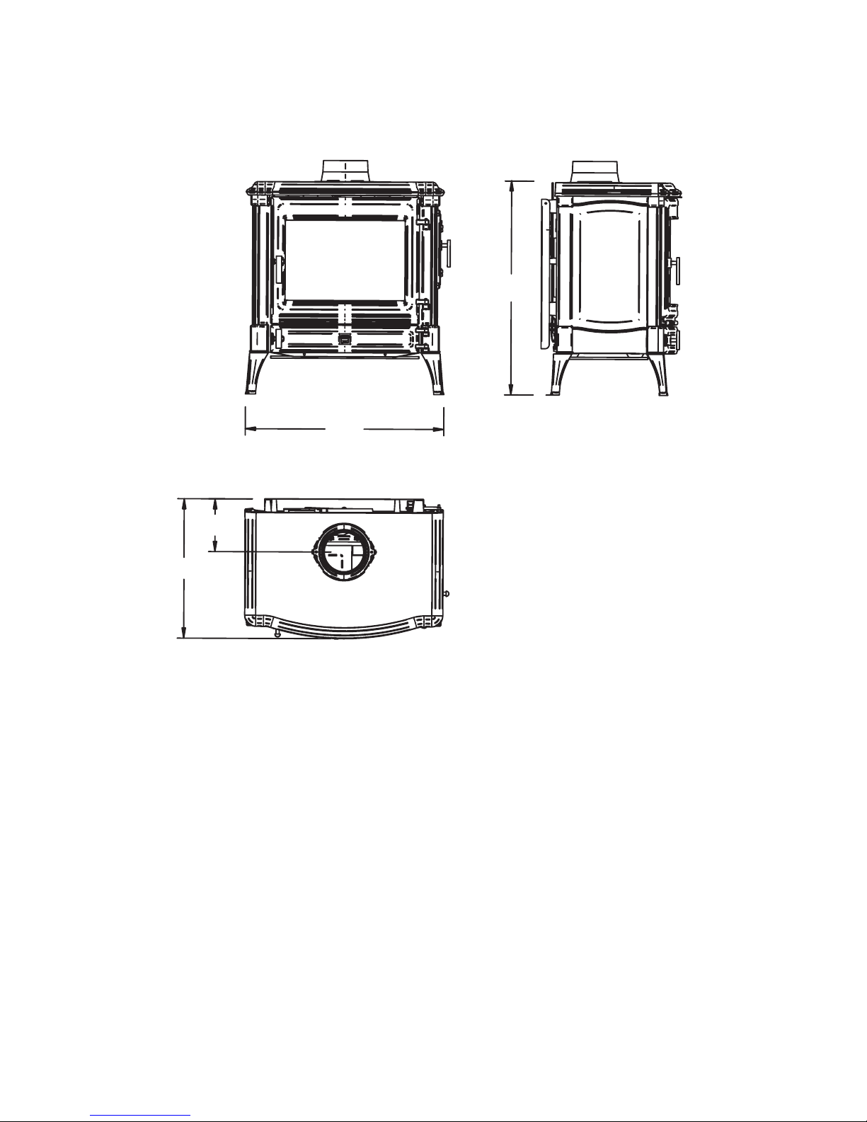
A
B
D
C
Model A B C D
Stanford 80 24" 28½" 16½" 6½"
Stanford 140 29" 31" 20½" 7½"
Harmony I 23¾" 26½" 15½" 6½"
Harmony III 29" 29½" 18½" 7½"
Dimensions

395823110a 5
Combustion System – Stanford 80 and Harmony I

395823110a 6
Combustion System – Stanford 140 and Harmony III
395823110a 7
INSTALLATION
Clearances to Combustibles - Stanford 80 & Harmony I
The following clearances may only be reduced by means approved by the regulatory
authority.
Refer to chart for single or double wall pipe
Back and Side Wall Clearances
Connector pipe A B C D
Single wall 27.5’’ 24’’ 27’’ 18’’
Double wall 21.5’’ 18’’ 27’’ 18’’
Minimum Ceiling Height: 7’
Corner Clearances
Connector pipe E F
Single wall 19’’ 27’’
Double wall 11’’ 19’’
Minimum Ceiling Height: 5’
395823110a 8
Clearances to Combustibles - Stanford 140 & Harmony III
The following clearances may only be reduced by means approved by the regulatory
authority.
Refer to chart for single or double wall pipe
Back and Side Wall Clearances
Connector pipe A B C D
Single wall 18’’ 13’’ 32’’ 20’’
Double wall 14.5’’ 10’’ 28.5’’ 17’’
Minimum Ceiling Height: 7’
Corner Clearances
Connector pipe E F
Single wall 16’’ 27’’
Double wall 7’’ 18’’
Minimum Ceiling Height: 7’

395823110a 9
Standard Installation
1. Position the unit no closer than the minimum clearances to combustible
materials. Check that no overhead cross members in the ceiling or roof will be
cut. Reposition unit if necessary, being careful not to move closer than the
minimum clearances.
2. A non-combustible floor protector (hearth extension) must be installed under
the unit. The floor protector must extend a minimum of 16 inches (450 mm)
beyond the front and side doors and 8 inches (200 mm) beyond the left side.
The floor protector must be equivalent to 1/2 inch (9.5mm) with a k factor of at
least 0.84 Btu/inch°F
Determining Thickness Requirements of Alternate Floor Protection Materials
The following formula gives the means of determining thickness of alternate
materials:
k of the alternate material x thickness of = thickness of
k of the specified material specified material alternate material
For example common brick has a k value of 5.0. The following would
determine the thickness necessary:
5.0 x 1/2 inch = 3.0 inches of common brick
0.84
3. Mark the position of the required floor protector on the floor. Remove the unit
and install the floor protector.
4. Position the unit on the floor protector at the proper clearances.
5. Install a 6-inch diameter, minimum 24 MSG black or 26 MSG blued steel
connector pipe on the flue collar of the unit.
• The stove is NOT to be connected to any air distribution duct or system.
• A chimney connector shall not pass through an attic or roof space,
closet or similar concealed space, or a floor, or ceiling. Where passage
through a wall or partition of combustible construction is desired, the
installation shall conform to CAN/CSA-B365, Installation Code for SolidFuel-Burning Appliances and Equipment. (Canadian installations only )
6. Use a chimney connector adapter to connect the chimney connector up to the
chimney. The small ends of the chimney connector should all point down for a
drip free installation. Position all seams toward the back for aesthetics. The
chimney connector must be 6-inch diameter.
 Loading...