

Page 1

Y
e-lite
fabrication/assembly and
Installation instructions
Part NO.
February 2013
WLS
Page 2

E-Lite Fabrication, Assembly and Installation Instructions
TABLE OF CONTENTS
SECTION PAGE
I. General Notes and Guidelines …………………………………………..…3-4
II. E-Lite “Stick Built” Channel Base Assembly………………..……….…5
III. E-Lite “Stick Built” Internal Support Channel Assembly…………...6
IV. E-Lite “Stick Built” Aluminum Panel Installation……………………...7-8
V. E-Lite “Stick Built” Terminator Channel Attachment…………………9
VI. E-Lite “Stick Built” Face Cap Attachment………………………….…….10
VII. E-Lite (Optional) End Cap Attachment …………………………………..11
VIII. E-Lite “Module Built” Base Frame Assembly……………………….…..12-13
IX. E-Lite “Module Built” Aluminum Panel ………………………………….14
X. E-Lite “Module Built” Aluminum Panel Module ……………………….15
XI. E-Lite “Module Built” Base Attachment ……………………………….….16
XII. E-Lite “Module” Installation .…………..…..……..…………………..…….17-18
XIII. E-Lite “Module” Alignment Clips Installation ….………………….…….19
Note: Please reference EFCO's "Understanding Condensation" brochure which can be obtained through your EFCO
representative.
Condensation will form on any surface when unfavorable conditions (interior temperature and relative
humidity and exterior temperature) are present. When the formation of excessive condensation is a concern, it is
highly recommended that a design professional is utilized to perform an analysis of the shop drawings to recommend
the best possible installation methods. Please contact your EFCO representative for information on EFCO's Thermal
Analysis Services.
Many current installation practices lead to an increase in the possibility of the formation of condensation.
Though not all inclusive, the list of examples below illustrates conditions under which condensation is likel y to occur:
1. Bridging system thermal break with non-thermally bro ken metal fla shing or lintels that are exposed
to the exterior
2. System exposure to cold air cavities
3. Interior relative humidity levels not maintained at recommended levels, see EFCO’s “Understanding
Condensation” brochure
4. Inadequate separation between system and surrounding condition at perimeter
5. Product combinations during the shop drawing stage that result in bridging thermal
breaks of one or all products involved
Minimizing Condensation
Note: These installation instructions are a supplement to the approved shop drawings
and are to be used in conjunction with those drawings.
EFCO CORPORATION 6/2012 PART NO. YWLS Page 2 of 19
Page 3

E-Lite Fabrication, Assembly and Installation Instructions
Section I: General Notes and Guidelines
A. HANDLING / STORING / PROTECTING ALUMINUM - The following
precautions are recommended to assure early acceptance of your products and
workmanship.
1. HANDLE CAREFULLY- Store with adequate separation between
components so the material will not rub together. Store material off the
ground. Protect materials against weather elements and other construction
trades.
2. KEEP MATERIAL AWAY FROM WATER, MUD, AND SPRAY - Prevent
cement, plaster, and other materials from contacting and damaging the
finish. Do not allow moisture to be trapped between the finished surface and
the wrapping material.
3. PROTECT MATERIALS AFTER ERECTION - Wrap or erect screens of
plastic sheeting over material. Cement, plaster, terrazzo, and other alkaline
materials are very harmful to the finish and are to be removed with soap and
water before hardening. Under no circumstances should these materials be
allowed to dry or permanent staining will occur.
B. GENERAL GUIDELINES - The following practices are recommended for all
installations:
1. REVIEW APPROVED SHOP DRAWINGS – Become thoroughly familiar
with the project. Shop drawings govern when conflicting information exists in
these installation instructions.
2. INSTALL ALL FRAMING MATERIAL PLUMB, LEVEL, AND TRUE –
Proper alignment and relationships to benchmarks and column centerlines, as
established by the architectural drawings and the general contractor, must be
maintained.
3. THE SEQUENCE OF ERECTION SHOULD BE COORDINATED WITH THE
PROJECT SUPERINTENDENT TO PREVENT DELAYS AND MINIMIZE THE RISK
OF MATERIAL DAMAGE. NOTE: IF ADDITIONAL ANCHORS ARE
REQUIRED, COORDINATE AND SUPERVISE ANCHOR PLACEMENT
WITH THE GENERAL CONTRACTOR.
4. Verify that all job site conditions and accompanying substrates receiving the
installation are in accordance with the contract documents. If deviations
occur, notification must be given IN WRITING to the general contractor and
differences resolved before proceeding further with the installation in the
questionable area.
EFCO CORPORATION 6/2012 PART NO. YWLS Page 3 of 19
Page 4

E-Lite Fabrication, Assembly and Installation Instructions
Section I: General Notes and Guidelines
5. Prevent all aluminum from coming in direct contact with masonry or dissimilar
materials by means of an appropriate primer.
6. Follow EFCO framing installation instructions.
Verify contents of all material shipments received upon their arrival. Verify quantity
and correct finishes. NOTIFY EFCO IMMEDIATELY OF ANY DISCREPANCIES OR
DAMAGE, WHICH MAY HAVE OCCURRED
Basic Design Guidelines
E–Lite is to be used for maximizing daylight potential in Southern Exposed Glazed Framing
Products.
E-Lite should be located at a height above the floor that does not interrupt flow of foot
traffic.
E-Lite projection must not exceed 36” from the mounting wall product or substrate.
E-Lite nonexposed internal structural components are typically mill finish; however, they
may be painted or anodized per preference. Aluminum panels will be painted as specified.
It is suggested that a nonspecular light colored finish be used for the upper surface of the
shelf to maximize the reflection of daylight into the space.
[It is advised that local building and fire code officials be consulted for applications with E Lite and fire sprinkler systems.]
E-Lite is designed to be a self supporting sun control device. It is not intended to be used
for storage of potted plants, books, etc. Do not place any objects on the E - Lite System or
use as a support handle or step.
[Additional loads (potted plants, books, etc.) may be possible to accommodate on a per
project basis.]
E-Lite System is designed as an accessory for EFCO Corporation Curtain Wall and
Storefront Products. Contact your local representative for product specific attachment
details.
E-Lite System CANNOT be installed on any INSIDE GLAZED Curtain Wall or Storefront
horizontals. Contact your local representative for specific product details.
E-Lite System MUST NOT
“bridge” any expansion joint or expansion mullion.
EFCO CORPORATION 6/2012 PART NO. YWLS Page 4 of 19
Page 5

E-Lite Fabrication, Assembly and Installation Instructions
Section II: E-Lite “Stick Built” Channel Base Assembly
1.) Fabricate, Assemble, and Anchor E-Lite Channel Base.
A.) Start with the channel base. Cut to length, locate and drill all anchor and support strut attachment holes.
Strut attachment
holes (4 per strut)
*
#13D8
Channel Base
B.) Attach all struts with the lead-point attachment screws through the channel base into the strut and tighten firmly.
Strut attachment screws
Channel base anchor screws (N.B.E.)
Light Shelf support strut, centerline to centerline
spacing not to exceed 24” O.C.
C.) Attach the channel base support / strut assembly to the glazed wall product or substrate with
quantity of fasteners. (
*Attachment fasteners are only sized and provided by EFCO when attachment is to EFCO material.)
Channel Base anchor holes *
Channel Base
*appropriate size and
Horizontal framing mullion or vertical wall substrate
Support Strut
Channel Base
EFCO CORPORATION 6/2012 PART NO. YWLS Page 5 of 19
Page 6
g
E-Lite Fabrication, Assembly and Installation Instructions
Section III: E-Lite “Stick Built” Internal Support Channel Assembly
1. Fabricate and Install Internal Support Channel.
A.) The internal support channel must be cut to length (nominally 4” less than strut centerline to centerline dimension).
Locate and drill all attachment holes in the support channel. (Typically the same anchor screw is used at the
internal channel support as used to anchor the channel base.)
#13D9
#13D8
B.) Align drill a clear hole in the channel base and a pilot hole in the horizontal mullion. (This is recommended even if
self drilling screws are used to avoid binding or breaking of the screw.)
C.) Install internal support channel equally spaced between the support struts. Tighten attachment screws firmly.
±
Framin
Framing system or wall substrate
Channel Base
system or wall substrate
Support StrutSupport Channel
Support Strut
Support Channel
EFCO CORPORATION 6/2012 PART NO. YWLS Page 6 of 19
Page 7

A
E-Lite Fabrication, Assembly and Installation Instructions
Section IV: E–Lite “Stick Built” Aluminum Panel Installation
1. Sizing the 1/8” aluminum sheet (sheared to make size dimensions).
A.) The make size dimensions for the 1/8” aluminum sheet are not to exceed 36” X 120”. The make sizes can be
easily calculated by adding up the centerline to centerline dimensions of the support struts in long runs, and
subtracting .125 at the intermediate
recommended that a .125 gap be left between the aluminum panels at increments not to exceed 120” of panel
length. The .125 gaps MUST OCCUR at the support strut locations.
panel locations, and adding .562 at the end panel locations. It is also
Support Channel
2. Loading the Aluminum Sheet Panels.
A.) The top aluminum sheet panel can be slid into place with the nonspecular reflective finish facing up. Take
care to square the panels and the struts. DO NOT FASTEN the panel to the struts.
luminum Sheet Panels
Support Strut
EFCO CORPORATION 6/2012 PART NO. YWLS Page 7 of 19
Page 8

–
A
E-Lite Fabrication, Assembly and Installation Instructions
Section IV: E-Lite “Stick Built” Aluminum Panel Installation
B.) Insert the bottom panel in the same manner as the upper, squaring and spacing the struts down the length of
the light shelf. The aluminum panel, once seated, should extend approximat ely ¼” past the end of the struts.
luminum Sheet Panels
C.) Once the bottom panels are in place, support the assembly at each strut approximately ¼” higher than the
desired level above the finished floor. With panels supported and level along the run, align drill and countersink
the bottom panel at each strut location. Then pin with the flat head fasteners provided. This will minimize
unleveling due to sag over time. On panels that extend up to the maximum depth, it may be necessary to pin
both top and bottom panels at the strut locations in the “flexed” position as illustrated below.
E-Lite in supported “flex” position
Level line
Lite in unsupported “pinned” position
E
Level line
EFCO CORPORATION 6/2012 PART NO. YWLS Page 8 of 19
Page 9

E-Lite Fabrication, Assembly and Installation Instructions
Section V: E–Lite “Stick Built” Terminator Channel Attachment
1. Fabricate and Install Terminator Channel.
A.) The terminator channel must be cut to length. Locate and drill all strut attachment holes in the channel.
#13E0
B.) Align the holes in the terminator channel with the races in the end of the strut, and attach with the lead-point
screws. After all screws have been started, go back and tighten all screws firmly.
Glazed Wall / Substrate
Glazed Wall / Substrate
Support Strut
Terminator Channel
Support Strut
Terminator Channel
EFCO CORPORATION 6/2012 PART NO. YWLS Page 9 of 19
Page 10

E-Lite Fabrication, Assembly and Installation Instructions
Section VI: E–Lite “Stick Built” Face Cap Attachment
1. Fabricate and Install Face Cap.
A.) The face cap must be cut to length.
Face Cap
B.) Engage the face cap on the upper snap and rotate onto the lower snap. It may be necessary to use a block
of wood and a mallet.
Face cap fully snapped-on
EFCO CORPORATION 6/2012 PART NO. YWLS Page 10 of 19
Page 11

“
r
E-Lite Fabrication, Assembly and Installation Instructions
Section VII: E-Lite (Optional) End Cap Attachment
On some applications, the light shelf does not terminate at an abutting wall, and the raw edges of
the horizontal members are exposed. In this case, EFCO offers an optional finished end cap plate
to be attached to the support struts to close off the end(s) of the light shelf unit.
1. Fabricate and Attach End Cap.
Note: The end cap may be square cut to the depth of the light shelf and attached to the support strut with
screws. There are a number of alternative attachment methods that could be used, including mastic,
pop-rivets, etc. However, EFCO recommends using screws to provide a secure attachment that may
also be disassembled should the need arise.
Undercut countersunk hole for #8 FHSMS
#13E2
Note: Any “raw or sharp” aluminum edges should be smoothed with a file or emery cloth and touch-up paint
applied. EFCO provides air dry touch-up paint in any of the standard colors. For custom air dry
touch-up paint, contact your local representative for availability and pricing. Any exposed flat head
screws should be filled and painted to minimize their exposure.
Raw,” “sharp”, aluminum edges must be smoothed and
counte
EFCO CORPORATION 6/2012 PART NO. YWLS Page 11 of 19
sunkholes with fastener heads should be painted.
Page 12

A
A
E-Lite Fabrication, Assembly and Installation Instructions
Section VIII: E-Lite “Module Built” Base Frame Assembly
The “Module Built” E-Lite refers to the system of fabrication and assembly, so as to allow the light
shelf to be fabricated and built into modules, transported to the job-site, and loaded into the
nchor Base Channel. The E-Lite Module Built system uses the same material; it is only
fabricated and assembled in a different manner. The assumption is that the E-Lite material can
be ordered in stock lengths, fabricated, and assembled in the customer’s shop, then attached to a
previously set curtain wall, storefront, or substrate wall.
1. Fabricate the Support Struts.
A.) The struts have what is called a “peel vee” and can be run across a table saw to cut a kerf at the 2” mark so
the material to be removed can be broken off with a pair of pliers.
2. Fabricate Internal Support Channel and Terminator Channel.
.) Locate and drill all strut attachment hole patterns in the support and terminator channels as indicated below.
EFCO CORPORATION 6/2012 PART NO. YWLS Page 12 of 19
Page 13

r
E-Lite Fabrication, Assembly and Installation Instructions
Section VIII: E-Lite “Module Built” Base Frame Assembly
2. Assemble E-Lite Module Frame.
A.) Assemble components as shown into ladders, tighten all fasteners firmly.
Strut to internal base Tek attachment screws
Strut to internal base lead-point attachment screws
Internal Base
Notched Ends
Terminator Channel
Strut lead-point attachment screws
E-Lite Support Strut centerline to centerline
spacing is not to exceed 24” O.C.
Completed E-Lite Module Ladde
EFCO CORPORATION 6/2012 PART NO. YWLS Page 13 of 19
Page 14

A
E-Lite Fabrication, Assembly and Installation Instructions
Section IX: E-Lite “Module Built” Aluminum Panel
1.) Load Aluminum Panels into E-Lite Module Ladder.
A.) Assemble components as shown into ladders, tighten all fasteners firmly.
Aluminum Panel
Top and Bottom
Assembled Module
Ladder Framing
2.) Square the E-Lite Module Ladder to the Panels and Pin.
.)Flush the edges of the aluminum panel with the module ladder and clamp as a unit. Recheck for squareness.
B.)Align drill and countersink the aluminum panels at 12” on center. Pin the panel with the Tek
screws supplied, tighten all fasteners firmly. Make sure the fastener heads are at least flush or
better yet, slightly recessed below the surface of the aluminum panel to minimize interference.
Drill and countersink aluminum panel for
Tek attachment screws top and bottom
EFCO CORPORATION 6/2012 PART NO. YWLS Page 14 of 19
Page 15

”
T
T
E-Lite Fabrication, Assembly and Installation Instructions
Section X: E-Lite “Module Built” Aluminum Panel Module
1.) E-Lite Module Panel
Tek attachment screws, top
and bottom at 12” on center
Module Length
Standard Module Depths
, 18”, 20”, 22”, 24”, 26”, 28”, 30”, 32”, 34”, 36”]
[16
Module Frame Depth
Module Panel Depth
op Panel
Support Strut
erminator Channel
Bottom Panel
Internal Base
EFCO CORPORATION 6/2012 PART NO. YWLS Page 15 of 19
Page 16

A
A
A
A
E-Lite Fabrication, Assembly and Installation Instructions
Section XI: E-Lite “Module Built” Base Attachment
1.) E-Lite Base
.) Locate the horizontal component or substrate where the E–Lite will be attached.
Note: Typically the top of the base will be flush with the top of the horizontal.
B.) Level
the E-Lite Attachment Base in the “perpendicular to the wall” plane. While securing the
base to the vertical wall, avoid “flexing” or “bowing” the E-Lite Base extrusion. (This will make
it difficult to load the rigid E-Lite Module panels into the base.)
#13D8
ttachment Base
Vertical Curtain Wall, Storefront, or Substrate
ttachment Base
ttachment Base Fasteners
When E-Lite System is attached to
Note:
EFCO Corporation Curtain Wall or Storefront
Products, the size, type, spacing, and quantity
of fasteners will be recommended based on
the depth of E-Lite System. Attachment
fastener recommendation to any other (nonEFCO) product or substrate must be designed
accordingly by responsible party.
EFCO CORPORATION 6/2012 PART NO. YWLS Page 16 of 19
Page 17

A
A
A
V
E-Lite Fabrication, Assembly and Installation Instructions
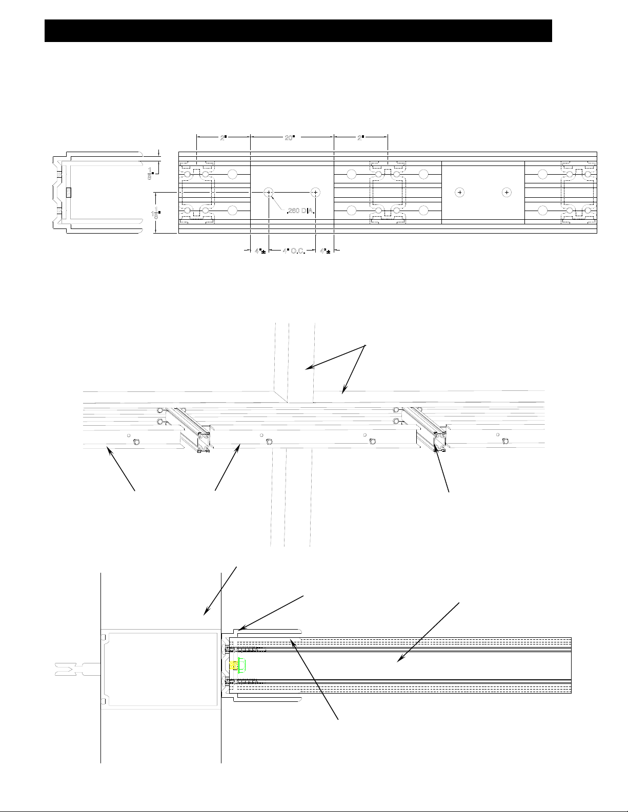
Section XII: E-Lite Module Installation
1.) Install Light Shelf Panel Module into Base.
Horizontal Mullion
.) Load the E-Lite Panel Module into the Base and support temporarily.
B.) Leave a recommended nominal 1/8” gap between the panel modules.
(This gap should be defined on the shop drawings.)
Note: Typically the top of the Base will be flush with the top of the horizontal mullion.
Flush
ttachment Base
ertical Mullion
Tek Attachment Screws
E-Lite Panel Module
Note:
E-Lite MUST NOT bridge any
expansion joint or expansion mullion.
ttachment Base
EFCO CORPORATION 6/2012 PART NO. YWLS Page 17 of 19
Page 18

A
E-Lite Fabrication, Assembly and Installation Instructions
Section XII: E-Lite Module Installation
C.) Align Light Shelf Panel Module into Base (Temporarily support terminating edge).
ttachment Base
E-Lite Panel Module
D.) Attach Light Shelf Panel Module into Base.
E-Lite Panel Module
Tek attachment screws top and bottom 12” O.C.
1/8” gap between E-Lite Modules
EFCO CORPORATION 6/2012 PART NO. YWLS Page 18 of 19
Page 19

Alig
Alig
A
E-Lite Fabrication, Assembly and Installation Instructions
Section XIII: E-Lite Module Alignment Clips Installation
1.) Attach Alignment Clip.
.) Locate the alignment clips at the nominal 1/8” module gaps. The clips are designed
to bridge the gap and clear all of the module frame assembly screws.
nment Clip
B.) Attach the clip with the Tek screws supplied. One (1) screw for each of the fixed holes
first and one (1) screw in the approximate center of the adjacent slotted hole into the
next light shelf module. It is expected that some minor alignment / adjustments will be
needed before the clip is firmly seated, and then the screws are tightened.
nment Clip TEK Screws
C.) See SECTION VI for the Face Cap Attachment and SECTION VII for the End Cap Attachment.
EFCO CORPORATION 6/2012 PART NO. YWLS Page 19 of 19
 Loading...