

Page 1
EBC-3330
SmartEC Embedded Box PC
User Manual
Version 1.1
Published January 2016
Copyright©2016 EFCO. All rights reserved.
Page 2

i
SmartEC Embedded Box PC
EBC-3330
Revision History
Revision
Date
Description
1.0
2015/07/30
First release
1.1
2016/02/24
Add revision history
1.2
2016/04/11
Change product name
Page 3

ii
SmartEC Embedded Box PC
EBC-3330
Copyright Notice
This document is copyrighted, 2016. All rights are reserved. The original manufacturer
reserves the right to make improvements to the products described in this manual at
any time without notice.
No part of this manual may be reproduced, copied, translated, or transmitted in any
form or by any means without the prior written permission of the original
manufacturer. Information provided in this manual is intended to be accurate and
reliable. However, the original manufacturer assumes no responsibility for its use, or
for any infringements upon the rights of third parties that may result from its use.
The material in this document is for product information only and is subject to change
without notice. While reasonable efforts have been made in the preparation of this
document to assure its accuracy, EFCO assumes no liabilities resulting from errors or
omissions in this document, or from the use of the information contained herein.
EFCO reserves the right to make changes in the product design without notice to its
users.
Acknowledgement
All other products’ name or trademarks are properties of their respective owners.
Microsoft Windows® is a registered trademark of Microsoft Corp.
ITE is a trademark of Integrated Technology Express, Inc.
IBM, PC/AT, PS/2, and VGA are trademarks of International Business Machines
Corporation.
Intel® and Pentium® are trademark of Intel Corp.
All other product names or trademarks are properties of their respective owners.
Page 4

iii
SmartEC Embedded Box PC
EBC-3330
Packing List
Before setting up your product, please ensure the following items have been shipped:
1 x EBC-3330
1 x Product DVD with User Manual(PDF) and Drivers
If any of these items are missing or damaged, please contact your distributor or sales
representative immediately.
About Manual
This User Manual contains all the essential information, such as detailed descriptions
and explanations on the product’s hardware and software features (if any), its
specifications, dimensions, jumper/connector settings/definitions, and driver
installation instructions (if any), to facilitate users in setting up their product.
Users may refer to http://www.efcotec.com for the latest version of this document.
Product Warranty (2 years)
EFCO warrants to you, the original purchaser, that each of its products will be free
from defects in materials and workmanship for two years from the date of purchase.
This warranty does not apply to any products which have been repaired or altered by
persons other than repair personnel authorized by EFCO, or which have been subject
to misuse, abuse, accident or improper installation. EFCO assumes no liability under
the terms of this warranty as a consequence of such events.
Because of EFCO’s high quality-control standards and rigorous testing, most of our
customers never need to use our repair service. If an EFCO product is defective, it will
be repaired or replaced at no charge during the warranty period. For out-of-warranty
repairs, you will be billed according to the cost of replacement materials, service
Page 5

iv
SmartEC Embedded Box PC
EBC-3330
time, and freight. Please consult your dealer for more details.
If you think you have a defective product, follow these steps:
1. Collect all the information about the problem encountered. (For example, EFCO
product Spec, other software and hardware used, etc.) Note anything abnormal
and list any onscreen messages you get when the problem occurs.
2. If your product is diagnosed as defective, obtain an RMA (Return Merchandise
Authorization) number from your account sales or EFCO website. This allows us to
process your return more quickly.
3. Carefully pack the defective product, a fully-completed repair and replacement
order card and photocopy proof of purchase date (such as your sales receipt) in a
shippable container. A product returned without proof of the purchase date is not
eligible for warranty service.
4. Write the RMA number visibly on the outside of the package and ship it prepaid to
EFCO.
Warnings, Cautions and Notes
Warnings indicate conditions, which if not observed, can cause personal
injury!
Cautions are included to help you avoid damaging hardware or losing
data.
Notes provide optional additional information.
Page 6

v
SmartEC Embedded Box PC
EBC-3330
Safety Instructions
Please read the following safety instructions carefully. It is advised that you keep this
manual for future references.
1. All cautions and warnings on the device should be noted.
2. Make sure the power source matches the power rating of the device.
3. Position the power cord so that people cannot step on it. Do not place anything
over the power cord.
4. Always completely disconnect the power before working on the system’s
hardware. 5. No connections should be made when the system is powered as a
sudden rush of
power may damage sensitive electronic components.
6. If the device is not to be used for a long time, disconnect it from the power supply
to avoid damage by transient over-voltage.
7. Always disconnect this device from any AC supply before cleaning.
8. While cleaning, use a damp cloth instead of liquid or spray detergents.
9. Make sure the device is installed near a power outlet and is easily accessible.
10. Keep this device away from humidity.
11. Place the device on a solid surface during installation to prevent falls.
12. Do not cover the openings on the device to ensure optimal heat dissipation.
13. Watch out for high temperatures when the system is running.
14. Do not touch the heat sink or heat spreader when the system is running.
15. Never pour any liquid into the openings. This could cause fire or electric shock.
16. As most electronic components are sensitive to static electrical charge, be sure to
ground yourself to prevent static charge when installing the internal components.
Use a grounding wrist strap and contain all electronic components in any staticshielded containers.
17. If any of the following situations arises, please contact our service personnel:
I. Damaged power cord or plug.
II. Liquid intrusion to the device.
III. Exposure to moisture.
IV. Device is not working as expected or in a manner as described in this
manual.
V. The device is dropped or damaged.
VI. Any obvious signs of damage displayed on the device.
Page 7

vi
SmartEC Embedded Box PC
EBC-3330
18. DO NOT LEAVE THIS DEVICE IN AN UNCONTROLLED ENVIRONMENT WHERE THE
STORAGE TEMPERATURE IS BELOW 0° C (32°F) OR ABOVE 60°C (140°F) TO
PREVENT DAMAGE.
FCC Statement
FCC Class A:
This equipment has been tested and found to comply with the limits for a Class A
digital device, pursuant to part 15 of the FCC Rules. These limits are designed to
provide reasonable protection against harmful interference when the equipment is
operated in a commercial environment. This equipment generates, uses, and can
radiate radio frequency energy and, if not installed and used in accordance with the
instruction manual, may cause harmful interference to radio communications.
Operation of this equipment in a residential area is likely to cause harmful
interference in which case the user will be required to correct the interference at his
own expense.
Page 8

vii
SmartEC Embedded Box PC
EBC-3330
Contents
Revision History ....................................................................................................................................... i
Copyright Notice .................................................................................................................................... ii
Acknowledgement ................................................................................................................................. ii
Packing List ............................................................................................................................................ iii
About Manual ....................................................................................................................................... iii
Product Warranty (2 years) ................................................................................................................... iii
Warnings, Cautions and Notes .............................................................................................................. iv
Safety Instructions ................................................................................................................................. v
FCC Statement ....................................................................................................................................... vi
Contents ............................................................................................................................................... vii
Chapter 1 ................................................................................................................................................ 1
1.1 Introduction ............................................................................................................................. 2
1.2 Features .................................................................................................................................... 2
1.3 Specifications ........................................................................................................................... 3
Chapter 2 ................................................................................................................................................ 6
2.1 Dimension ................................................................................................................................ 7
2.2 Standard I/O Indication ............................................................................................................ 8
2.2.1 I/O Indication View ....................................................................................................... 8
2.2.2 Power ON/OFF Button .................................................................................................. 8
2.2.3 Power Input Connector ................................................................................................. 8
2.2.4 Audio Connector ........................................................................................................... 9
2.2.5 USB Connector .............................................................................................................. 9
2.2.6 Ethernet Connector(LAN)............................................................................................ 10
2.2.7 VGA Connector ............................................................................................................ 11
2.2.8 High definition video output Connector ..................................................................... 11
2.3 Jumpers of the Main Board .................................................................................................... 12
2.3.1 Jumper Description ..................................................................................................... 12
2.3.2 Jumper settings list and location ................................................................................ 13
2.4 Connectors of the Main Board ............................................................................................... 14
2.4.1 Connectors list and location ........................................................................................ 14
2.4.2 DC-IN Connector ......................................................................................................... 14
2.4.3 CMOS Battery Connector(J3) ...................................................................................... 14
2.4.4 S/PDIF-OUT Connector ................................................................................................ 15
2.4.5 MIC Connector ............................................................................................................ 15
Page 9

viii
SmartEC Embedded Box PC
EBC-3330
2.4.6 GPIO(J22) Connector ................................................................................................... 15
2.4.7 COM A(J23) & COM B(J24) Connector ........................................................................ 16
2.4.8 Front Header(J25) Connector ..................................................................................... 16
2.4.9 PCI Express Mini Card ................................................................................................. 16
2.4.10 SATA 1 Connector ...................................................................................................... 18
2.4.11 SATA_PWR(CN3) Connector ...................................................................................... 18
2.4.12 EPORT Connector ...................................................................................................... 18
2.4.13 LVDS Connector ......................................................................................................... 19
2.4.14 SO-DIMM Connector ................................................................................................. 20
2.4.15 Micro SD Slot ............................................................................................................. 20
2.5 Peripheral Installation ............................................................................................................ 20
2.5.1 Memory Installation .................................................................................................... 20
2.5.2 Full-Size PCI Express Mini Card Installation ................................................................ 22
2.5.3 Half-Size PCI Express Mini Card Installation ................................................................ 23
2.5.4 Micro SD Card Installation........................................................................................... 23
Chapter 3 .............................................................................................................................................. 25
3.1 BIOS Introduction ................................................................................................................... 26
3.2 Continue ................................................................................................................................. 27
3.3 Boot Manager ........................................................................................................................ 27
3.4 Device Management .............................................................................................................. 28
3.5 Boot From File ........................................................................................................................ 29
3.6 Secure Boot Option ................................................................................................................ 30
3.7 SCU (System Control Unit) ..................................................................................................... 32
3.7.1 Main ............................................................................................................................ 32
3.7.2 Advanced ..................................................................................................................... 33
3.7.3 Security ....................................................................................................................... 56
3.7.4 Power .......................................................................................................................... 57
3.7.5 Boot ............................................................................................................................. 62
3.7.6 Exit ............................................................................................................................... 67
Chapter 4 .............................................................................................................................................. 68
4.1 Driver Installation ................................................................................................................... 69
Chapter A ............................................................................................................................................. 71
A.1 Option Accessories I/O Indication ......................................................................................... 72
A.1.1 COM Port I/O (P/N: EFCP1169X1-L) ............................................................................ 72
4.1.2 Ethernet Port I/O (P/N: EFCP1168X1-L) ...................................................................... 73
4.1.3 GPIO Port I/O (P/N: EFCP1170X1-L) ............................................................................ 74
4.1.4 USB 3.0 Port I/O (P/N: EFCP1171X1-L) ........................................................................ 74
Chapter B.............................................................................................................................................. 76
Page 10

ix
SmartEC Embedded Box PC
EBC-3330
B.1 Watchdog Timer Initial Program ............................................................................................ 77
B.2 Watchdog Sample Program ................................................................................................... 79
Chapter C .............................................................................................................................................. 82
C.1 I/O Address Map .................................................................................................................... 83
C.2 IRQ Mapping Chart ................................................................................................................ 84
C.3 Memory Address Map ........................................................................................................... 87
Page 11

1
SmartEC Embedded Box PC
EBC-3330
Chapter 1
GENERAL INTRODUCTION
Page 12

2
SmartEC Embedded Box PC
EBC-3330
1.1 Introduction
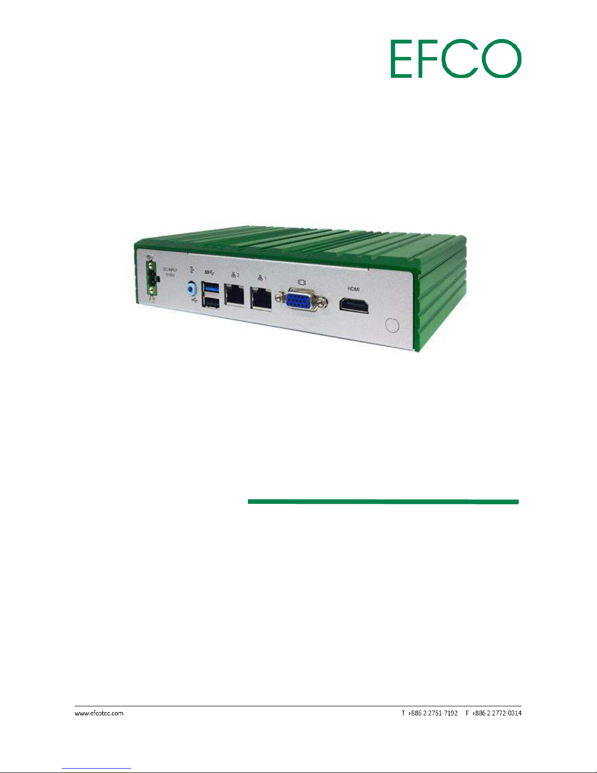
The Fanless Embedded Box PC with multi I/O interfaces.
The SmartEC series devices are designed in compact sizes and using the latest energyefficient Intel® Bay Trail platform. The fanless architecture ensures silent operation
with maximum reliability and minimum dust intake, making the SmartEC ideal to use
in various environments. For enhanced flexibility, the system supports dual display
capability and storage expansion availability. Additionally, the device supports HighDefinition video format to provide the ultimate video experience.
The SmartEC is compatible with various applications, such as Thin Client, Factory
Automation, and Digital Signage with limited space. Multiple I/O interfaces provide
the connection to the most common peripherals. With its smart design, low energy
consumption and great connectivity, the SmartEC is definitely the best choice for your
diverse applications.
Applications.
Industrial Controller
Digital Signage
Kiosk Engine
Factory Automation
POS PC
Remote Terminal Unit (RTU)
IoT Gateway
1.2 Features
• Fanless design with low power consumption
• Supports Intel® Bay Trail platform
• 1 x 204 pin DDR3L SO-DIMM 1333 max up to 8GB
• Supports VESA mount
• Standard I/O:
1 x USB3.0, 1x USB2.0
Dual display for 1 VGA & 1 High definition video output
1 x mSATA supported
Page 13

3
SmartEC Embedded Box PC
EBC-3330
12V Power input (Optional for 5V ~ 55V)
1 x Line-out
1.3 Specifications
System
CPU
♦ Intel® Bay Trail platform
System Memory
♦ 1 x 204 pin DDR3L SO-DIMM 1333 max up to 8GB
Chipset
♦ SoC integrated
Storage
♦ 1 x mSATA supported
Watchdog Timer
♦ 255 levels, 255 sec.
External I/O
♦ 1 x VGA, 1 x High definition video output
♦ 1 x USB 2.0
♦ 1 x USB 3.0
♦ 2 x 10/100/1000Mbps Ethernet
♦ 1 x power on/off button
Page 14

4
SmartEC Embedded Box PC
EBC-3330
♦ 1 x Audio (Line-Out)
WiFi
♦ Optional for 802.11 b/g/n
Power Supply
♦ 12V DC Power input (Optional for 5V ~ 55V)
Expansion Slot
♦ 1 x full-size PCI Express Mini card (for mSATA)
♦ 1 x half-size PCI Express Mini card with USB signal (for optional Wireless module)
Mechanical
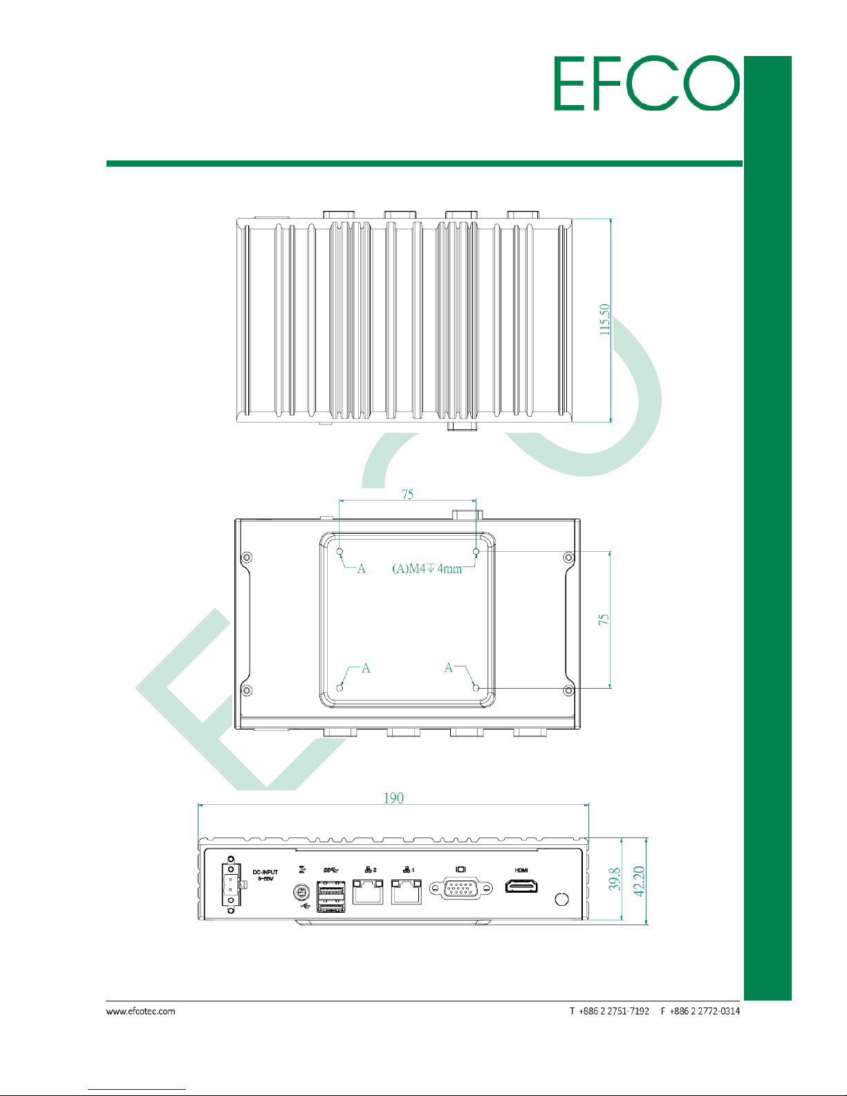
Dimension
♦ 190(W) x 115.5(D) x42.2(H) mm
Weight
♦ 2.5kg / 4kg
Page 15

5
SmartEC Embedded Box PC
EBC-3330
Mounting Type
♦ VESA
Environmental
Operation Temperature
♦ 0~+60°C, (32F – 140 F)
Relative Humidity
♦10%-90% (non-condensing)
Certificate Software Support
Certification
♦ CE, FCC Class A
OS Information
♦ Windows 7 Professional 64bit, Windows Embedded standard 7 64bit, Linux Ubuntu
14.04.3 LTS 64bit
Page 16

6
SmartEC Embedded Box PC
EBC-3330
Chapter 2
HARDWARE INFORMATION
Page 17
7
SmartEC Embedded Box PC
EBC-3330
2.1 Dimension
Unit: mm
Photo_1 – EBC-3330 mechanical dimension drawing-1
Photo_2 – EBC-3330 mechanical dimension drawing-2
Photo_3 – EBC-3330 mechanical dimension drawing-3
Page 18
8
SmartEC Embedded Box PC
EBC-3330
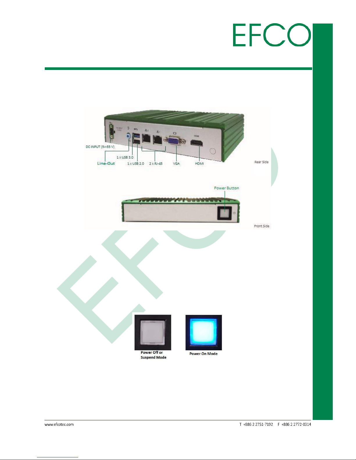
2.2 Standard I/O Indication
2.2.1 I/O Indication View
Phot_ 4 – EBC-3330 I/O View
2.2.2 Power ON/OFF Button
The EBC-3330 has a Power On/Off button with LED indicator. Using the Power button,
the device can be switched on, suspended, shut down immediately, or shut down
with the delay of 4 seconds.
Photo_5 – Power Button
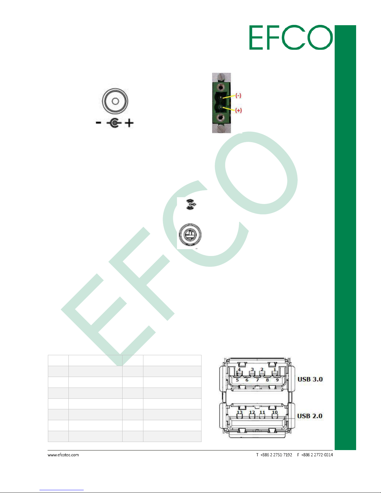
2.2.3 Power Input Connector
The EBC-3330 has 2 external DC power input connectors: DC 12V Power Jack and DC
Page 19
9
SmartEC Embedded Box PC
EBC-3330
5V - 55V 2-pin terminal block connector as shown in the following images.
Photo_6 – Power Input Connector_12V Photo_7 – Power Input Connector_5~55V
2.2.4 Audio Connector
EBC-3330 provides a single 3.5mm ear phone jack connector with Line-out function.
Photo_8 – Ear Phone Jack Connector
2.2.5 USB Connector
EBC-3330 provides two (1 x USB 2.0 & 1 x USB 3.0) USB interface connectors. The
interface is compliant with USB UHCI, Rev. 2.0 & 3.0. Both connectors are Plug and
Play compatible, allowing you to connect or disconnect a device whenever you want,
without turning off the computer.
Pin
Signal Name
Pin
Signal Name
1
+5VSB
2
USB0_D-
3
USB0_D+
4
GND
5
USB1_SSRX-
6
USB1_SSRX+
7
GND
8
USB1_SSTX-
9
USB1_SSTX+
10
+5VSB
11
USB1_D-
12
USB1_D+
13
GND
Page 20

10
SmartEC Embedded Box PC
EBC-3330
Table_1 – USB Pin Assignments Photo_9 – USB Connector
When Insertion USB device, please check device's direction.
2.2.6 Ethernet Connector(LAN)
EBC-3330 provides two RJ-45 LAN interface connectors which are fully compliant with
IEEE 802.3u 10/100/1000 Mbps CSMA/CD standards. It is equipped with Intel I210
and supports Wake-On-LAN function. The Ethernet port uses a standard RJ-45 jack
connector with LED indicators on the front side to show Active/Link status and Speed
status.
Pin
Signal Name
Pin
Signal Name
1
TX+, MDI0+
2
TX-, MDI0-
3
RX+, MDI1+
4
MDI2+
5
MDI2-
6
RX-, MDI1-
7
MDI3+
8
MDI3-
Table_2 – LAN Pin Assignments Photo_10 – Ethernet Connector
LAN1 LED State Table
LAN LED Status
LED1 (Link)
LED2 (SPEED)
Network link is not established or system
power off
Amber/ Blinking
OFF
10 Mbps (10 Base-T)
10 Full Duplex
Amber
OFF
Link/Active
Blinking
OFF
100 Mbps (100 Base-TX)
100 Full Duplex
Amber
Green
Link/Active
Blinking
ON
1000 Mbps (1000 Base-T)
1000 Full Duplex
Amber
Orange
Link/Active
Blinking
ON
Table_3 – LAN1 LED State
LAN2 Intel i210-AT LED State Table
Page 21
11
SmartEC Embedded Box PC
EBC-3330
LAN LED Status
LED1 (Link)
LED2 (SPEED)
Network link is not established or system
power off
OFF
OFF
10 Mbps (10 Base-T)
10 Full Duplex
Amber
OFF
Link/Active
Blinking
OFF
100 Mbps (100 Base-TX)
100 Full Duplex
Amber
Green
Link/Active
Blinking
ON
1000 Mbps (1000 Base-T)
1000 Full Duplex
Amber
Orange
Link/Active
Blinking
ON
Table_4 – LAN2 LED State
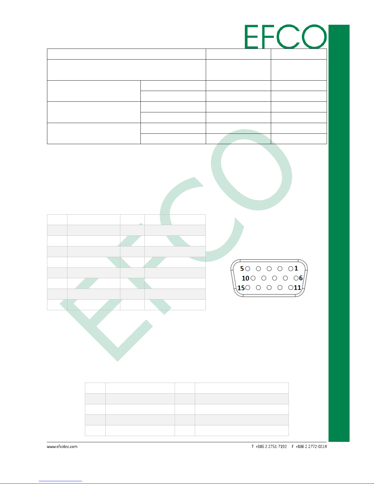
2.2.7 VGA Connector
EBC-3330 provides a high resolution VGA interface through a 15-pin D-sub connector
in order to support a VGA CRT monitor. The maximum resolution is 1920 x 1080.
Pin
Signal Name
Pin
Signal Name
1
RED
2
GREEN
3
BLUE
4
NC
5
GND
6
GND
7
GND
8
GND
9
NC
10
GND
11
NC
12
DDC Date
13
H-Sync
14
V-Sync
15
DDC Clock
Table_5 – VGA Pin Assignments Photo_11 – VGA Connector
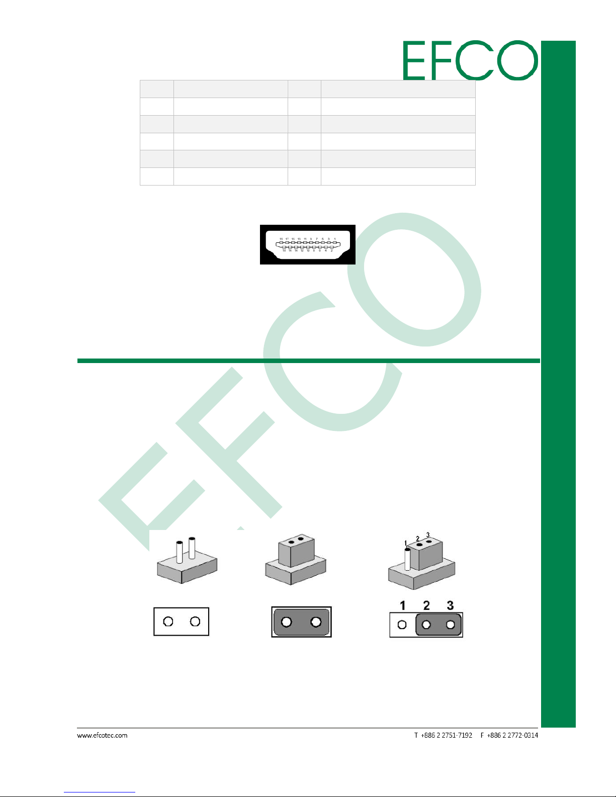
2.2.8 High definition video output Connector
EBC-3330 provides a high resolution High definition video output Port.
Pin
Signal Name
Pin
Signal Name
1
TMDS Data2+
2
TMDS Data2 Shield
3
TMDS Data2–
4
TMDS Data1+
5
TMDS Data1 Shield
6
TMDS Data1–
7
TMDS Data0+
8
TMDS Data0 Shield
Page 22
12
SmartEC Embedded Box PC
EBC-3330
9
TMDS Data0–
10
TMDS Clock+
11
TMDS Clock Shield
12
TMDS Clock–
13
CEC
14
Reserved (N.C. on device)
15
SCL
16
SDA
17
DDC/CEC Ground
18
+5V Power
19
Hot Plug Detect
Table_6 – High definition video output Pin Assignments
Photo_12 – High definition video output Connector
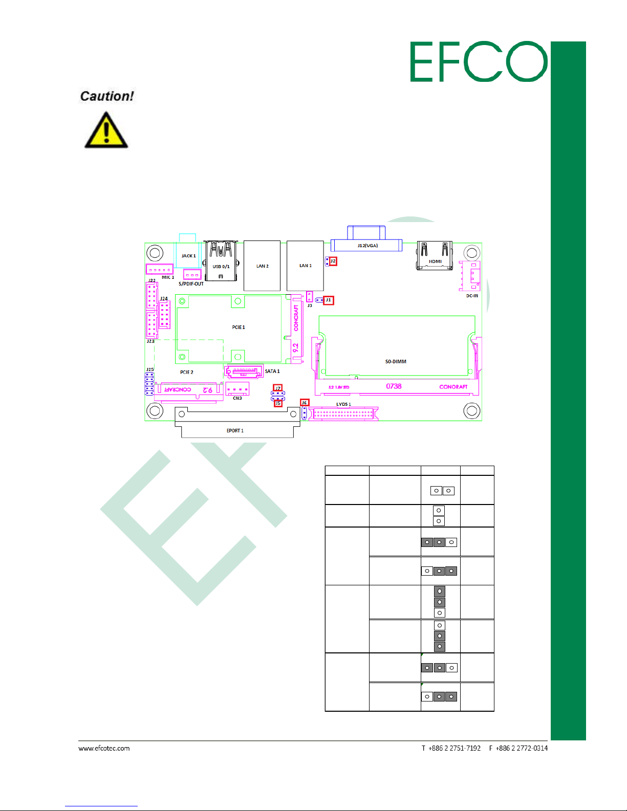
2.3 Jumpers of the Main Board
2.3.1 Jumper Description
A jumper is a metal bridge used to close an electric circuit. It consists of two metal
pins and a small metal clip that slides over the pins to connect them. To close a
jumper, you can connect the pins with the clip. To open a jumper, you just need
remove the clip. Sometimes a jumper will have three pins, labeled 1, 2 and 3. In this
case you would connect either pins 1 and 2, or 2 and 3.
The jumper settings are schematically depicted in this manual as follows.
Photo_13 – Jumper Setting
Page 23
13
SmartEC Embedded Box PC
EBC-3330
To avoid damaging the computer, always turn off the power supply
before setting jumpers. A pair of needle-nose pliers may be helpful when
working with jumpers. If you have any doubts about the best hardware
configuration for your application, contact your local distributor or sales
representative before you make any changes.
2.3.2 Jumper settings list and location
Photo_14 – Jumper Location
J1: N/A
J2: CMOS CLR
J5: LCD Panel Backlight Power Select
J6: LCD Panel Power Select
J7: LCD PANEL Backlight Enable Select
Table_7 – Jumper Setting
Jumper No. Function Photo Setting
2 1
N/A
2
1
1 2 3
1~2
(Default)
1 2 3
2~3
1
2 1~2
3
1
2 2~3
3 (Default)
1 2 3
1~2
(Default)
1 2 3
2~3
N/A
J5
+12V
+5V
SRTCRST_N
RTEST_N
J1
J2
J6
+3.3V
+5V
J7
High Active
Low Active
Page 24
14
SmartEC Embedded Box PC
EBC-3330
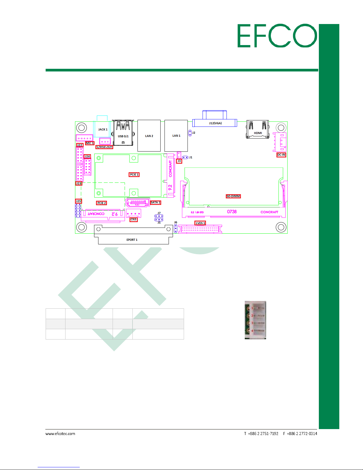
2.4 Connectors of the Main Board
2.4.1 Connectors list and location
Photo_15 – Connector Location
2.4.2 DC-IN Connector
ATX 2x2 power connector input (12V).
Pin
Signal Name
Pin
Signal Name
1
GND
2
+12V
3
+12V
4
GND
Table_8 – ATX Power Connector Pin Assignments Photo_16 – ATX Power connector
2.4.3 CMOS Battery Connector(J3)
CMOS battery connector.
Page 25
15
SmartEC Embedded Box PC
EBC-3330
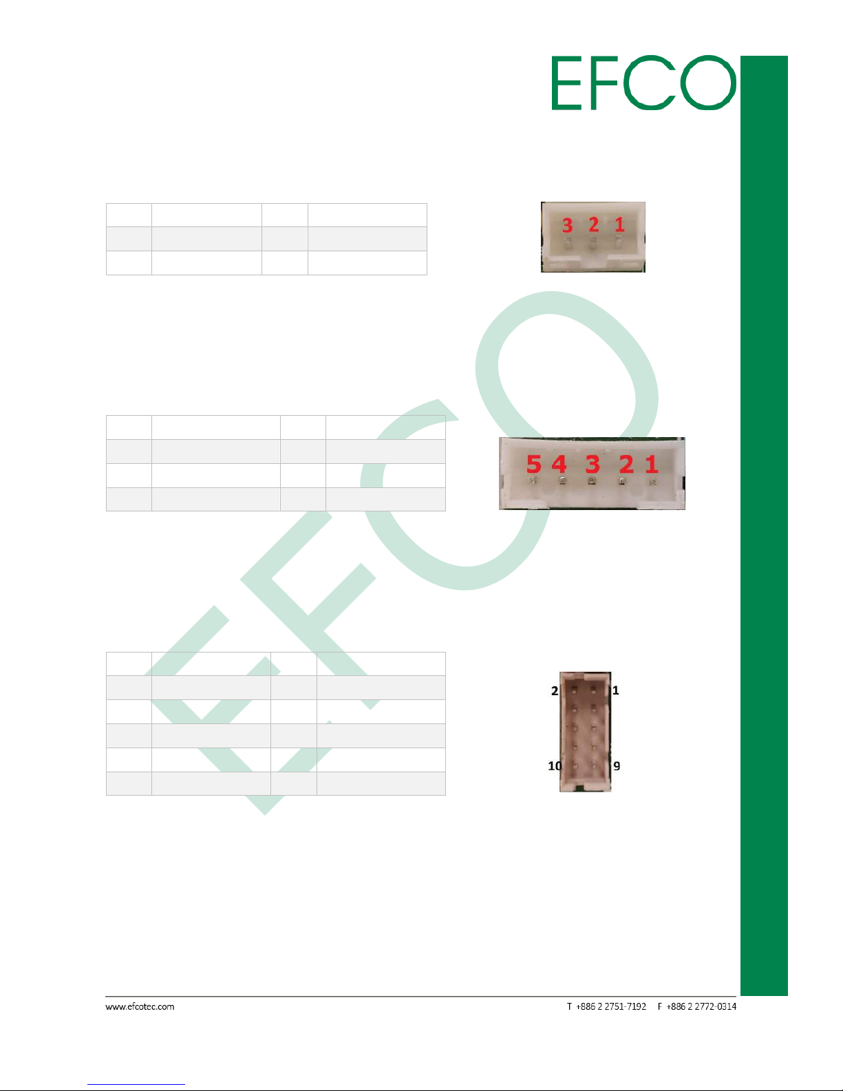
2.4.4 S/PDIF-OUT Connector
S/PDIF Connector
Pin
Signal Name
Pin
Signal Name
1
+5V
2
S/PDIF-OUT
3
GND
Table_9 – S/PDIF-OUT Connector Pin Assignments Photo_17 – S/PDIF-OUT connector
2.4.5 MIC Connector
Line-In Connector.
Pin
Signal Name
Pin
Signal Name
1
Line-In_Detect
2
GND
3
Line-In_L
4
Line-In_R
5
GND
Table_10 – MIC Connector Pin Assignments Photo_18 – Line-In connector
2.4.6 GPIO(J22) Connector
General Purpose Input / Output connector.
Pin
Signal Name
Pin
Signal Name
1
NC 2 SIO_GPO1
3
SIO_GPO2
4
SIO_GPO3
5
SIO_GPO4
6
SIO_GPI1
7
SIO_GPI2
8
SIO_GPI3
9
SIO_GPI4
10
NC
Table_11 – GPIO Connector Pin Assignments Photo_19 – GPIO connector
Page 26
16
SmartEC Embedded Box PC
EBC-3330
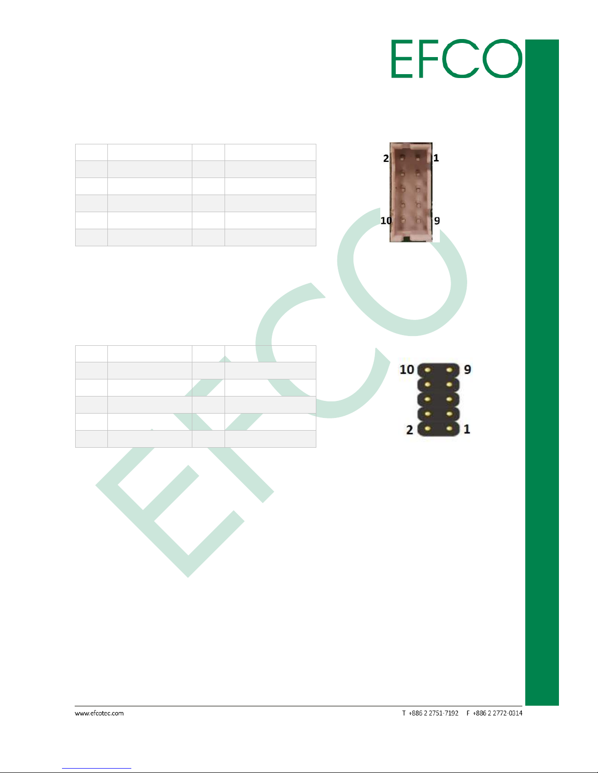
2.4.7 COM A(J23) & COM B(J24) Connector
RS-232 port.
Pin
Signal Name
Pin
Signal Name
1
DCD#
2
RXD
3
TXD
4
DTR#
5
GND
6
DSR#
7
RTS#
8
CTS#
9
RI#
10
NC
Table_12 – COM Connector Pin Assignments Photo_20 – COM connector
2.4.8 Front Header(J25) Connector
Front Panel Header Connector
Pin
Signal Name
Pin
Signal Name
1
+3.3V
2
+5V_ALW
3
HDD_ACT#
4
GND
5
GND
6
PWRBTN#
7
RSTBTN#
8
GND
9
NC
10
NC
Table_13 – Front Panel Header Pin Assignments Photo_21 – Front Panel Header connector
2.4.9 PCI Express Mini Card
The EBC-3330 provides two PCI Express Mini Card (Full-Size x 1, Half-Size x 1).
PCIE_1 is Full-Size PCI Express Mini Card with only support mSATA device.
PCIE_2 is Half-Size PCI Express Mini Card. PCI Express Mini Card is a unique small size
form factor optimized for mobile computing platforms equipped with communication
applications. The small footprint connector can be implemented on SBCs, providing
the ability to insert different removable PCI Express Mini Cards. Using this approach
gives the flexibility to mount an upgradable, standardized PCI Express Mini Card
device without additional expenditure of a redesign.
Page 27

17
SmartEC Embedded Box PC
EBC-3330
Pin
Signal Name
Pin
Signal Name
1
WAKE#
2
+3.3V
3
NC 4 GND
5
NC 6 +1.5V
7
PCIE_CLK_REQ#
8
NC 9 GND
10
NC
11
REFCLK-
12
NC
13
REFCLK+
14
NC
15
GND
16
NC
17
PULL DOWN RESISTOR(1M)
18
GND
19
NC
20
W_DISABLE#
21
GND
22
PERST#
23
PERn0
24
+3.3V
25
PERp0
26
GND
27
GND
28
+1.5V
29
GND
30
SMB_CLK
31
PETn0
32
SMB_DATA
33
PETp0
34
GND
35
GND
36
USB_D-
37
GND
38
USB_D+
39
+3.3V
40
GND
41
+3.3V
42
NC
43
mSATA_mPCIe_detect
44
NC
45
CL_CLK
46
NC
47
CL_DATA
48
+1.5V
49
CL_RST#
50
GND
51
NC
52
+3.3V
53
GND
54
GND
Table_14 – PCI Express Mini Card Slot Pin Assignments
Photo_22 – Full-Size mPCIe slot Photo_23 – Half-Size mPCIe slot
Page 28
18
SmartEC Embedded Box PC
EBC-3330
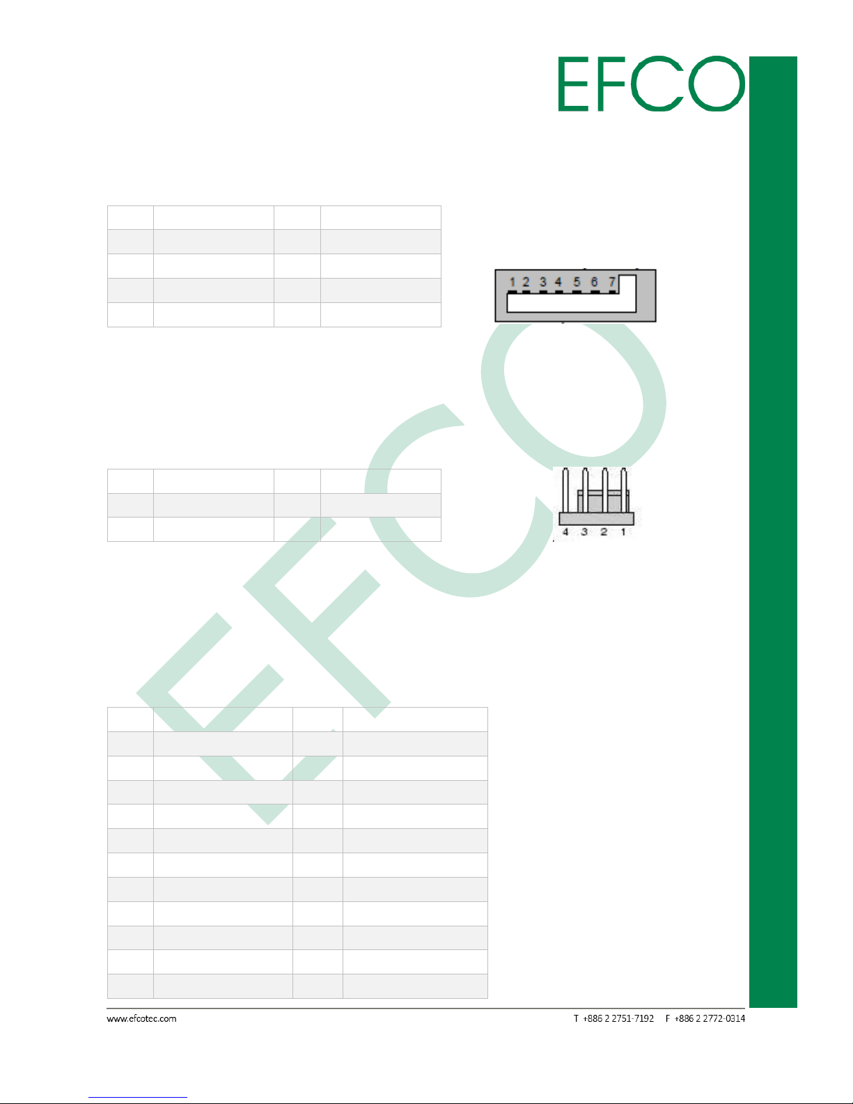
2.4.10 SATA 1 Connector
The EBC-3330 provides an SATA ports. The SATA ports support data rates up to 3GB/s.
Pin
Signal Name
Pin
Signal Name
1
GND
2
TX+
3
TX- 4 GND
5
RX-
6
RX+
7
GND
8
Table_15 – SATA Connector Pin Assignments Photo_24 – SATA connector
2.4.11 SATA_PWR(CN3) Connector
4 Pin connector for SATA HDD power output.
Pin
Signal Name
Pin
Signal Name
1
+12V
2
GND
3
GND
4
+5V
Table_16 – SATA Power Connector Pin Assignments Photo_25 – SATA Power connector
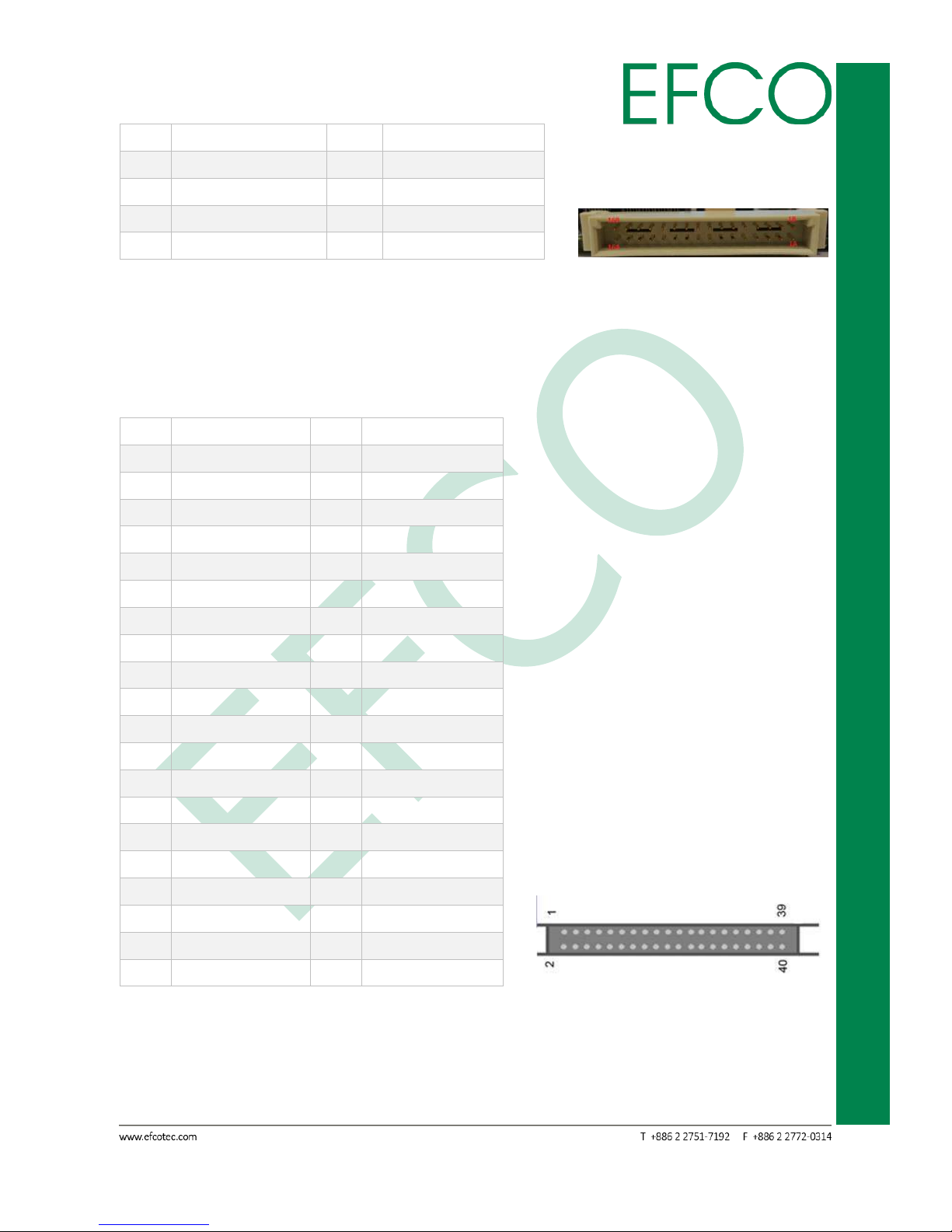
2.4.12 EPORT Connector
The EBC-3330 provides an E-Port to insert different EFCO expand I/O function boards.
About expand I/O board, please See section “Chapter A”.
Pin
Signal Name
Pin
Signal Name
1A
PCIE_CLK-
1B
RST#
2A
PCIE_CLK+
2B
GND
3A
PCIE_TX2_C_DN
3B
GND
4A
PCIE_TX2_C_DP
4B
GND
5A
PCIE_HX2_H_DN
5B
GND
6A
PCIE_HX2_H_DP
6B
USB1_EP_D-
7A
PCIE_EP_OC#
7B
USB1_EP_D+
8A
+3.3A_ALW
8B
+5V
9A
+3.3V
9B
+5V
10A
+3.3V
10B
+5V
11A
I2C_DAT
11B
SMB_CLK
Page 29
19
SmartEC Embedded Box PC
EBC-3330
12A
I2C_CLK
12B
SMB_DAT
13A
LPC_AD0
13B
LPC_CLK
14A
LPC_AD1
14B
FRAME#
15A
LPC_AD2
15B
SERIRQ
16A
LPC_AD3
16B
GND
Table_17 – E-PORT Connector Pin Assignments Photo_26 – E-PORT connector
2.4.13 LVDS Connector
The EBC-3330 offers a standard 40 pin LVDS connector.
Pin
Signal Name
Pin
Signal Name
1
VDD_BLT
2
VDD_BLT
3
LVDS_BPEN_JP
4
GND
5
LVDS_DIO_CLK
6
BLT_CTRL_ADJ
7
VDD_LCD
8
LVDS_DIO_DAT
9
VDD_LCD
10
VDD_LCD
11
GND
12
GND
13
LVDS_B0-
14
LVDS_A0-
15
LVDS_B0+
16
LVDS_A0+
17
GND
18
GND
19
LVDS_B1-
20
LVDS_A1-
21
LVDS_B1+
22
LVDS_A1+
23
GND
24
GND
25
LVDS_B2-
26
LVDS_A2-
27
LVDS_B2+
28
LVDS_A2+
29
GND
30
GND
31
LVDS_B_CLK-
32
LVDS_A_CLK-
33
LVDS_B_CLK+
34
LVDS_A_CLK+
35
GND
36
GND
37
LVDS_B3-
38
LVDS_A3-
39
LVDS_B3+
40
LVDS_A3+
Table_18 – LVDS Connector Pin Assignments Photo_27 – LVDS connector
Page 30
20
SmartEC Embedded Box PC
EBC-3330
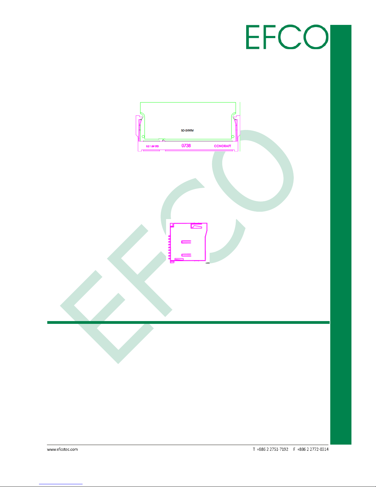
2.4.14 SO-DIMM Connector
EBC-3330 provides a standard specification 204 pin 1333MHz DDR3L SO-DIMM slot,
The memory max up to 8GB.
Photo_28 – Memory Slot
2.4.15 Micro SD Slot
EBC-3330 provides a standard specification Micro SD slot. The slot support push &
push to install or remove. Max support 64GB of the Class 10.
Photo_29 – Micro SD Slot
2.5 Peripheral Installation
2.5.1 Memory Installation
1. Disconnect the ac power adapter and all cables from the computer.
2. Remove bottom chassis 4 (M3 x 4L) screws.
Page 31

21
SmartEC Embedded Box PC
EBC-3330
Photo_30 – Bottom 4 screws location
3. Open aluminum bottom chassis.
Photo_31 – Open aluminum bottom chassis
4. Install or remove RAM.
Page 32

22
SmartEC Embedded Box PC
EBC-3330
Photo_32 – RAM slot
Please note that EBC-3330 can support DDR3L memory only.
2.5.2 Full-Size PCI Express Mini Card Installation
1. The step 1 ~ 3 the same Memory installation.
2. Install Full-size PCI express mini card and fix the (M2 x 4mm) screws.
Photo_33 – Full-size PCI Express Mini Card slot
Page 33

23
SmartEC Embedded Box PC
EBC-3330
1. Full-size PCI express mini card support mSATA device only.
2. If want to remove or replace device, please unlock (M2 x 4mm)
screws first.
2.5.3 Half-Size PCI Express Mini Card Installation
1. The step 1 ~ 3 the same Memory installation.
2. Install Half-size PCI express mini card and fix the (M2 x 4mm) screws.
Photo_34 – Half-size PCI Express Mini Card slot
If want to remove or replace device, please unlock (M2 x 4mm) screws
first.
2.5.4 Micro SD Card Installation
1. The step 1 ~ 3 the same Memory installation.
2. Remove 4 (M3 x 5L) screws, Power button and Power input two cables.
Page 34

24
SmartEC Embedded Box PC
EBC-3330
Photo_35 – Main board screw location
3. Turn of the MB to the other side, then install or remove the Micro SD card device.
Photo_36 – Micro SD slot
Please note that EBC-3330 can support 64GB of the Class 10 Micro SD.
Page 35

25
SmartEC Embedded Box PC
EBC-3330
Chapter 3
BIOS SETUP
Page 36

26
SmartEC Embedded Box PC
EBC-3330
3.1 BIOS Introduction
The Insyde BIOS ROM has a pre-installed Setup program that allows users to modify
basic system configurations, which is stored in the battery-backed CMOS RAM and
BIOS NVRAM so that the information is retained when the power is turned off. This
chapter describes the basic navigation of the EBC-3330 BIOS setup screens.
To enter BIOS Setup, press <Del> immediately while your computer is powering up.
Photo_37 – Insyden BIOS
The system no provides internal speaker. If an error, fatal or non-fatal.
The system will output an error message on your display.
Page 37

27
SmartEC Embedded Box PC
EBC-3330
3.2 Continue
If you mistakenly press to the BIOS setup program or to discard the changes. You can
click "Continue" item to into the boot process, then without rebooting the system.
3.3 Boot Manager
The function can fast select boot device. If want to cancel, please enter "ESC" key to
turn back.
Photo_38 – Boot Manager Setting
Page 38

28
SmartEC Embedded Box PC
EBC-3330
3.4 Device Management
The function is select primary video BIOS from <PCI> or <AGP>. If want to cancel,
please enter "ESC" key to turn back.
Photo_39 – Device Management Setting
Function Item
Select Item
Primary video BIOS
PCI (Default setting)
AGP
Table_19 – Device Management Setting
Page 39

29
SmartEC Embedded Box PC
EBC-3330
3.5 Boot From File
The function is select external USB device boot file. (If have more boot file)
If want to cancel, please enter "ESC" key to turn back.
Photo_40 – Boot From File Setting
Page 40

30
SmartEC Embedded Box PC
EBC-3330
3.6 Secure Boot Option
Photo_41 – Secure Boot Option Setting
After the setting change or cancel. When enter "ESC" key, the system will ask “Yes” or
“No” on the display.
Photo_42 – Secure Boot Option change
Anyway when select the “Yes” or “No”, the system will show reset information on the
display. Please enter the "OK" to restart computer.
Photo_43 – Secure Boot Option restart
Page 41

31
SmartEC Embedded Box PC
EBC-3330
Function Item
Select Item_1
Notes
Erase all secure boot
settings
Disabled (Default setting)
Enabled
Restore secure boot to
factory settings
Disabled (Default setting)
Enabled
Table_20 – Secure Boot Option Setting
Page 42
32
SmartEC Embedded Box PC
EBC-3330
3.7 SCU (System Control Unit)
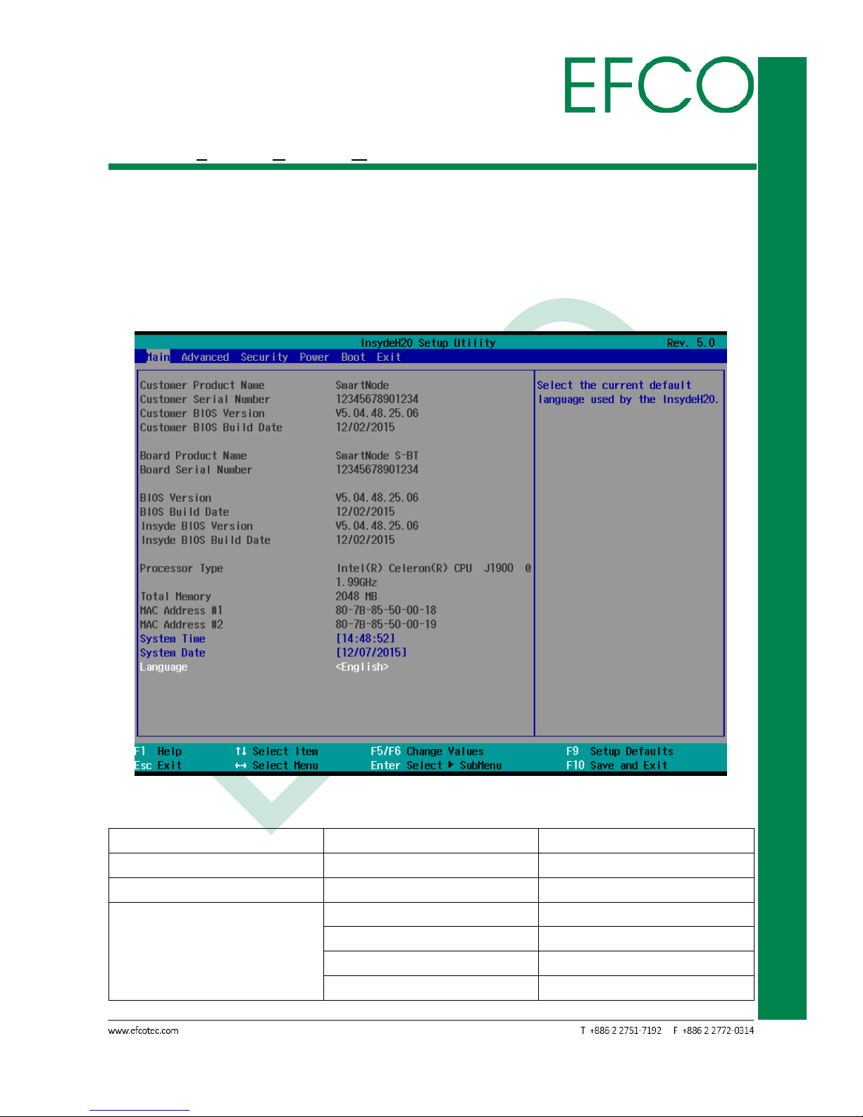
3.7.1 Main
EBC-3330 Main BIOS Setup page described about the Machine information. The
system time/date, language can be change. The Main BIOS Setup page screens and
described are shown below.
Photo_44 – SCU_Main Setting
Function Item
Select Item_1
Notes
System Time
N/A
System Date
N/A
Language
English (Default setting)
Francais
中文
Traditional Chinese
日本語
Japanese
Table_21 – SCU_Main Setting
Page 43

33
SmartEC Embedded Box PC
EBC-3330
3.7.2 Advanced
EBC-3330 Advanced BIOS Setup options are described in this section. User can select
any item in the frame of the screen, and to go to the sub menu for that item. All The
Advanced BIOS Setup screens are shown below. The sub menus are described on the
following pages.
Photo_45 – SCU_Advanced Setting
Page 44

34
SmartEC Embedded Box PC
EBC-3330
3.7.2.1 PCI Express Configuration
Photo_46 – Advanced_PCI Express Configuration Setting
EBC-3330 PCI Express Root Port 1 to 4 have the same default setting. Below table is
PCI Express Root Port 1 setting.
PCI Express Root Port 1 ~ 4: Control the PCI Express Root Port.
PCIE Port 1 ~ 4 Speed: Configure PCIe Speed.
PCIE Port 1 ~ 4 ASPM: Automatically enable ASPM based on reported capabilities and
know issues.
Function Item
Select Item_1
Select Item_2
PCI Express Root
Port 1
PCI Express Root
Port 1
Enabled (Default setting)
Disabled
PCIE Port 1 Speed
Auto (Default setting)
Gen1
Gen2
Page 45
35
SmartEC Embedded Box PC
EBC-3330
PCIE Port 1 ASPM
Disabled
L0s
L1
L0sL1
Auto (Default setting)
Table_22 – Advanced_PCI Express Configuration Setting
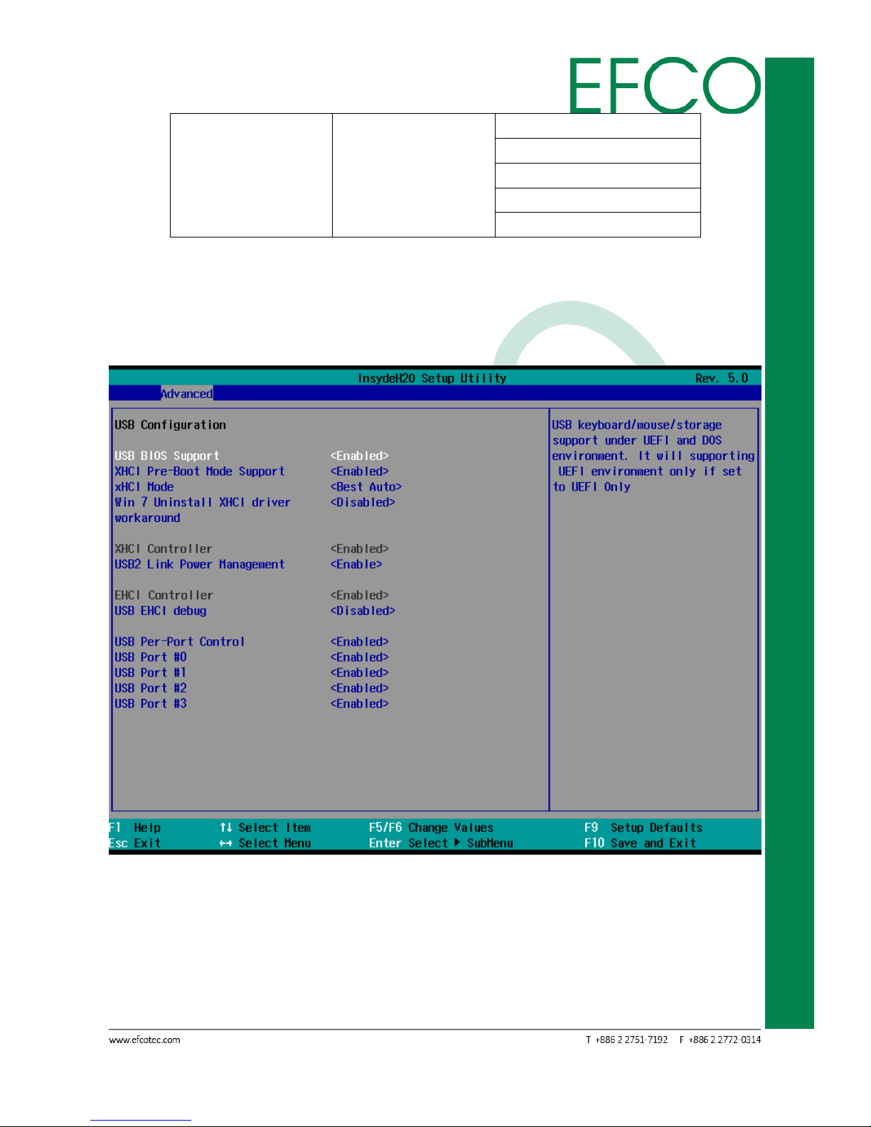
3.7.2.2 USB Configuration
Photo_47 – Advanced_USB Configuration Setting
USB Configuration
USB BIOS Support: USB keyboard/mouse/storage support under UEFI and DOS
environment. It will support UEFI environment only if set to UEFI
only.
Page 46

36
SmartEC Embedded Box PC
EBC-3330
XHCI Pre-Boot Mode Support: Enable/Disable XHCI Pre-Boot Mode Support.
XHCI Mode: Mode of operation of XHCI controller.
Win 7 Uninstall XHCI driver workaround: Enable/Disable Win7 Uninstall XHCI driver
workaround. When enable, Win7 USB(EHCI)
still can work after uninstall XHCI driver, but
WHCK test will fail.
Function Item
Select Item_1
USB BIOS Support
Disabled
Enabled (Default setting)
UEFI Only
XHCI Pre-Boot Mode
Support
Disabled
Enabled (Default setting)
XHCI Mode
Disabled
Enabled
Auto
Smart Auto
Best Auto (Default setting)
Win 7 Uninstall XHCI
driver workaround
Disabled (Default setting)
Enabled
Table_23 – Advanced_USB Configuration_USB BIOS Support Setting
XHCI Controller
USB2 Link Power Management: Enable/Disable USB2 Link Power Management.
Function Item
Select Item_1
USB2 Link Power
Management
Enable (Default setting)
Disable
Table_24 – Advanced_USB Configuration_USB2 Link Power Management Setting
EHCI Controller
USB EHCI debug: Enable/Disable USB EHCI debug capability.
USB Per-Port Control: Control each of the USB ports (0~9) disabling.
USB Port #0 ~ #3: Only select Enable/Disable.
Function Item
Select Item_1
USB EHCI debug
Disabled (Default setting)
Enabled
USB Per-Port Control
Disabled
Enabled (Default setting)
Page 47
37
SmartEC Embedded Box PC
EBC-3330
USB Port #0
Disabled
Enabled (Default setting)
USB Port #1
Disabled
Enabled (Default setting)
USB Port #2
Disabled
Enabled (Default setting)
USB Port #3
Disabled
Enabled (Default setting)
Table_25 – Advanced_USB Configuration_EHCI Controller Setting
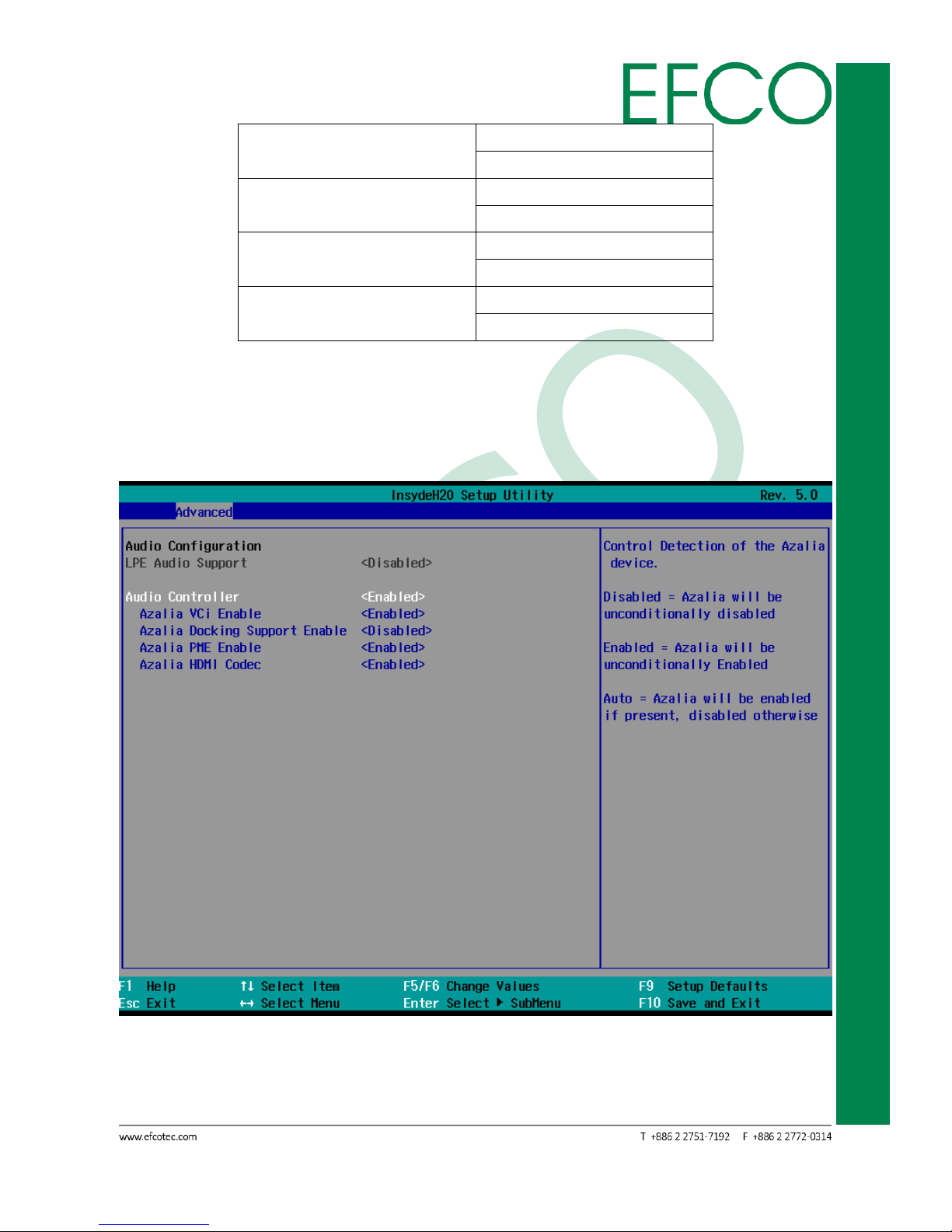
3.7.2.3 Audio Configuration
Photo_48 – Advanced_Audio Configuration Setting
Page 48

38
SmartEC Embedded Box PC
EBC-3330
Audio Controller: Control Detection of the Azalia device.
Disabled = Azalia will be unconditionally disabled.
Enabled = Azalia will be unconditionally enabled.
Auto = Azalia will be enabled if present, disabled otherwise.
Azalia VCi Enable: Enable/Disable Virtual Channel 1 of Audio Controller.
Azalia Docking Support Enable: Enable/Disable Azalia Docking Support of Audio
Controller.
Azalia PME Enable: Enable/Disable Power Management capability of Audio Controller.
Azalia HDMI Codec: Enable/Disable internal HDMI codec for Azalia.
Function Item
Select Item_1
Audio Controller
Disabled
Enabled (Default setting)
Auto
Azalia VCi Enable
Disabled
Enabled (Default setting)
Azalia Docking Support Enable
Disabled (Default setting)
Enabled
Azalia PME Enable
Disabled
Enabled (Default setting)
Azalia HDMI Codec
Disabled
Enabled (Default setting)
Table_26 – Advanced_Audio Configuration Setting
Page 49

39
SmartEC Embedded Box PC
EBC-3330
3.7.2.4 LPSS & SCC Configuration
Photo_49 – Advanced_LPSS & SCC Configuration Setting
LPSS & SCC Devices Mode: Set LPSS & SCC Device as ACPI or PCI mode.
LPSS & SCC Auto Switch: Auto Switch LPSS & SCC devices from ACPI mode to PCI
mode when OS not support ACPI mode.
Hide Unsupported LPSS devices: Hide Unsupported LPSS devices when in ACPI mode.
OS Selection: OS Selection.
Function Item
Select Item_1
LPSS & SCC Devices Mode
ACPI Mode (Default setting)
PCI Mode
LPSS & SCC Auto Switch
Disable
Enable (Default setting)
Hide Unsupported LPSS
devices
Disable
Enable (Default setting)
OS Selection
Windows (Default setting)
Android
Table_27 – Advanced_LPSS & SCC Configuration Setting
Page 50

40
SmartEC Embedded Box PC
EBC-3330
SCC Configuration
SCC SDIO Support: Enable/Disable SCC SDIO Controller.
SCC SD Card Support: Enable/Disable SCC SD Card Controller.
SDR25 Capability Support for SD Card: Disable/Enable SDR25 Capability in SD Card
controller.
Function Item
Select Item_1
SCC SDIO Support
Disabled (Default setting)
Enabled
SCC SD Card Support
Disabled
Enabled (Default setting)
SDR25 Capability Support
for SD Card
Disabled
Enabled (Default setting)
Table_28 – Advanced_LPSS & SCC Configuration_ SCC Configuration Setting
LPSS Configuration
LPSS DMA #1 Support: Disable/Enable LPSS DMA #1 Support.
LPSS DMA #2 Support: Disable/Enable LPSS DMA #2 Support.
LPSS I2C #1 Support: Disable/Enable LPSS I2C #1 Support.
LPSS PWM #1 Support: Disable/Enable LPSS PWM #1 Support.
LPSS PWM #1 Support: Disable/Enable LPSS PWM #2 Support.
Function Item
Select Item_1
LPSS DMA #1 Support
Disabled (Default setting)
Enabled
LPSS DMA #2 Support
Disabled
Enabled (Default setting)
LPSS I2C #1 Support
Disabled
Enabled (Default setting)
LPSS PWM #1 Support
Disabled (Default setting)
Enabled
LPSS PWM #2 Support
Disabled (Default setting)
Enabled
Table_29 – Advanced_LPSS & SCC Configuration_ LPSS Configuration Setting
Page 51

41
SmartEC Embedded Box PC
EBC-3330
3.7.2.5 Miscellaneous Configuration
Photo_50 – Advanced_Miscellaneous Configuration Setting
HPET – HPET Support: High Performance Event Timer support in Windows XP.
Enabled this feature, the HPET table will be add-into ACPI
tables.
State After G3: Specity what state to go to when power is re-applied after a power
failure (G3 state).
Clock Spread Spectrum: Enable Clock Chip’s Spread Spectrum feature.
UART Interface Selection: Select which UART interface to use.
Exl: Enabled/Disabled Exl.
BIOS Lock: Enable or Disable BIOS SPI region write protect.
PCI MMIO Size: Setup PCI MMIO size 0.75G, 1G, 1.25G, 1.5G, 2GB size.
PCI Express Dynamic Clock Gating: Enable/Disable PCIE Dynamic Clock Gating.
Force Legacy Free: Enabled/Disabled Force Legacy Free. (Force Disable KBC)
Serial IRQ: Enable/Disable Serial IRQ.
Serial IRQ Mode: Select Serial IRQ mode.
Page 52

42
SmartEC Embedded Box PC
EBC-3330
PCI 64-bit Decode: Allow system to support 64-bit BAR for PCI devices.
CRID: Enable/Disable CRID.
MRC Fast Boot: Enable/Disable MRC fast boot.
Function Item
Select Item_1
HPET – HPET Support
Disabled
Enabled (Default setting)
State After G3
S0 State (Default setting)
S5 State
Clock Spread Spectrum
Disabled (Default setting)
Enabled
UART Interface Selection
Internal UART (Default setting)
Super IO UART
Exl
Enabled
Disabled (Default setting)
BIOS Lock
Enabled (Default setting)
Disabled
PCI MMIO Size
Best Auto
0.75GB
1GB
1.25GB
1.5GB
2GB (Default setting)
PCI Express Dynamic Clock
Gating
Disabled (Default setting)
Enabled
Force Legacy Free
Disabled (Default setting)
Enabled
Serial IRQ
Disabled
Enabled (Default setting)
Serial IRQ Mode
Quiet Mode (Default setting)
Continuous Mode
PCI 64-bit Decode
Enabled
Disabled (Default setting)
CRID
Disabled (Default setting)
Enabled
MRC Fast Boot
Disabled
Enabled (Default setting)
Table_30 – Advanced_Miscellaneous Configuration Setting
Page 53

43
SmartEC Embedded Box PC
EBC-3330
3.7.2.6 Security Configuration
Photo_51 – Advanced_Security Configuration Setting
TXE: Enable/Disable TXE Device.
TXE HMRFPO: Enable/Disable HMRFPO message, system BIOS sends this message to
unlock the TXE region temporarily for writing.
TXE Firmware Update: Enable/Disable TXE FW update feature, used by Intel TXE FW
update tool.
TXE EOP Message: Send EOP message before enter OS. After sending EOP, some of
TXE command cannot be used.
TXE Unconfiguration Perform: TXE temporary disable.
Function Item
Select Item_1
TXE
Disabled
Enabled (Default setting)
Page 54

44
SmartEC Embedded Box PC
EBC-3330
TXE HMRFPO
Disabled (Default setting)
Enabled
TXE Firmware Update
Disabled (Default setting)
Enabled
TXE EOP Message
Disabled
Enabled (Default setting)
Table_31 – Advanced_Security Configuration Setting
3.7.2.7 Video Configuration
Photo_52 – Advanced_Video Configuration Setting
Video Configuration
Logo & SCU Resolution: Configuration logo & setup utility resolution.
Multi EDID Support: Enable/Disable Multi EDID Support for BIOS VIDEO[INT10] Driver.
Page 55

45
SmartEC Embedded Box PC
EBC-3330
Function Item
Select Item_1
Logo & SCU Resolution
Auto (Default setting)
640 x 480
800 x 600
1024 x 768
Multi EDID Support
Disabled (Default setting)
Enabled
Table_32 – Advanced_Video Configuration Setting
VBT Hook Configuration
Configure CRT as: Select Hardware CRT configuration.
CRT EDID Support: Enable/Disable CRT EDID support.
Configure DDI0 as: Select Hardware DDI0 configuration.
Configure DDI1 as: Select Hardware DDI1 configuration.
Configure eDP Panel Number as: Select eDP Panel Number.
LFP EDID Support: Enable/Disable LFP EDID Support.
EFP EDID Support: Enable/Disable EFP EDID Support.
Function Item
Select Item_1
Configure CRT as
Default
CRT (Default setting)
No Device
CRT EDID Support
Disabled
Enabled (Default setting)
Configure DDI0 as
Default
DisplayPort
HDMI/DVI (Default setting)
DisplayPort with HDMI/DVI Compatible
No Device
Configure DDI1 as
Default
eDP (Default setting)
DisplayPort
HDMI/DVI
DisplayPort with HDMI/DVI Compatible
No Device
Configure eDP Panel
Number as
800 * 600 18bit
1024 * 768 18bit(Default setting)
1024 * 768 24bit
Page 56

46
SmartEC Embedded Box PC
EBC-3330
1280 * 760 18bit
1280 * 800 18bit
1280 * 960 18bit
1280 * 1024 24bit
1366 * 768 18bit
1366 * 768 24bit
1440 * 900 24bit
1400 * 1050 24bit
1600 * 900 24bit
1680 * 1050 24bit
1680 * 1200 24bit
1920 * 1080 24bit
1920 * 1200 24bit
LFP EDID Support
Disabled
Enabled (Default setting)
EFP EDID Support
Disabled
Enabled (Default setting)
Table_33 – Advanced_VBT Hook Configuration Setting
IGD Configuration
Integrated Graphics Device: Enable = Enable integrated graphics device(IGD) when
selected as the primary video adaptor. Disable.
Disable = Always disable IGD.
Primary Display: Select which of IGD/PCI graphics device should be primary display.
RC6(Render Standby): Check to enable render standby support.
PAVC: Enable/Disable Protected Audio Video Control.
Power Management Lock: Enable/Disable PM lock.
DOP CG: Enable/Disable DOP clock gating.
GTT Size: Select the GTT size.
Aperture Size: Select the aperture size.
IGD – DVMT Pre-Allocated: Select DVMT5.0 Pre-Allocated(Fixed) graphics memory
size used by the internal graphics device.
IGD – DVMT Total Gfx Mem: Select the size of DVMT 5.0 that the internal graphics
device will use.
IGD Turbo: Enable/Disable IGD Turbo.
IGD Thermal: Enable/Disable IGD Thermal.
Spread Spectrum clock: Enable/Disable Spread Spectrum clock.
Page 57

47
SmartEC Embedded Box PC
EBC-3330
Function Item
Select Item_1
Integrated Graphics
Device
Disabled
Enabled (Default setting)
Primary Display
Auto (Default setting)
IGD
PCIe
RC6(Render Standby)
Enabled (Default setting)
Disabled
PAVC
Disabled
LITE Mode (Default setting)
SERPENT Mode
Power Management Lock
Enabled
Disabled (Default setting)
DOP CG
Enabled (Default setting)
Disabled
GTT Size
1MB
2MB (Default setting)
Aperture Size
128MB
256MB (Default setting)
512MB
IGD – DVMT Pre-Allocated
64M (Default setting)
96M
128M
160M
192M
224M
256M
288M
320M
352M
384M
416M
448M
480M
512M
IGD – DVMT Total Gfx
Mem
128M
256M (Default setting)
Page 58

48
SmartEC Embedded Box PC
EBC-3330
MAX
IGD Turbo
Auto (Default setting)
Enabled
Disabled
IGD Thermal
Disabled (Default setting)
Enabled
Spread Spectrum clock
Disabled (Default setting)
Enabled
Table_34 – Advanced_IGD Configuration Setting
3.7.2.8 Chipset Configuration
Photo_53 – Advanced_Chipset Configuration Setting
ISP Enable/Disable: Enable/Disable ISP PCI Device Selection.
ISP PCI Device Selection: Default ISP is PCI B0D2F0 for Windows boot. Linux boot to
select B0D3F0.
Page 59

49
SmartEC Embedded Box PC
EBC-3330
Function Item
Select Item_1
ISP Enable/Disable
Enabled (Default setting)
Disabled
ISP PCI Device Selection
Disabled
ISP PCI Device as B0D2F0(Default setting)
ISP PCI Device as B0D3F0
Table_35 – Advanced_Chipset Configuration Setting
3.7.2.9 Thermal Configuration
Photo_54 – Advanced_Thermal Configuration Setting
Critical Trip Point: This value controls the temperature of the ACPI Critical Trip Point –
the point in which the OS will shut the system off.
Passive Trip Point: This value controls the temperature of the ACPI Passive Trip Point –
Page 60

50
SmartEC Embedded Box PC
EBC-3330
the point in which the OS will begin throttling the processor.
Passive TC1 Value: This value sets the TC1 value for the ACPI passive cooling formula.
Range 1 – 16.
Passive TC2 Value: This value sets the TC2 value for the ACPI passive cooling formula.
Range 1 – 16.
Passive TSP Value: This item sets the TSP value for the ACPI passive cooling formula. It
represents in tenths of a second how often the OS will read the
temperature when passive cooling is enabled. Range 2 – 32.
Active Trip Points: Disable Active Trip Points
Function Item
Select Item_1
Critical Trip Point
Disabled
15℃
23℃
31℃
39℃
47℃
55℃
63℃
71℃
79℃
85℃
87℃
90℃ (Default setting)
Passive Trip Point
Disabled
15℃
23℃
31℃
39℃
47℃
55℃
63℃
71℃
79℃
85℃ (Default setting)
87℃
90℃
Passive TC1 Value
1 (Default setting)
Page 61

51
SmartEC Embedded Box PC
EBC-3330
Passive TC2 Value
5 (Default setting)
Passive TSP Value
10 (Default setting)
Active Trip Points
Disabled (Default setting)
15℃
23℃
31℃
39℃
47℃
55℃
63℃
71℃
79℃
85℃
87℃
90℃
Table_36 – Advanced_Thermal Configuration Setting
Page 62

52
SmartEC Embedded Box PC
EBC-3330
3.7.2.10 SATA Configuration
Photo_55 – Advanced_SATA Configuration Setting
SATA Controller: Disabled = Disables SATA controller.
Enabled = Enables SATA controller.
SATA Test Mode: Test mode enable/disable.
Chipset SATA Mode: Select SATA mode, AHCI or IDE.
SATA Speed: Select SATA speed.
SATA Port 0 Hot Plug Capability: If enabled, SATA port will be reported as Hot Plug
capable.
SATA Port 1 Hot Plug Capability: If enabled, SATA port will be reported as Hot Plug
capable.
SATA Port 0 Connected to an ODD: If enabled, when SATA port connected to an ODD
will enable software auto detection for media
insert and tray ejection.
Page 63

53
SmartEC Embedded Box PC
EBC-3330
SATA Port 1 Connected to an ODD: If enabled, when SATA port connected to an ODD
will enable software auto detection for media
insert and tray ejection.
Serial ATA Port 0
Serial ATA Port 0 device configuration.
Serial ATA Port 1
Serial ATA Port 1 device configuration.
Function Item
Select Item_1
SATA Controller
Disabled
Enabled (Default setting)
SATA Test Mode
Enabled
Disabled (Default setting)
Chipset SATA Mode
IDE
AHCI (Default setting)
SATA Speed
Gen1
Gen2(Default setting)
SATA Port 0 Hot Plug
Capability
Enabled
Disabled (Default setting)
SATA Port 1 Hot Plug
Capability
Enabled
Disabled (Default setting)
SATA Port 0 Connected to
an ODD
Disabled (Default setting)
Enabled
SATA Port 1 Connected to
an ODD
Disabled (Default setting)
Enabled
Table_37 – Advanced_SATA Configuration Setting
Serial ATA Port 0 & 1 item need connector SATA device, then just can be
select.
Page 64

54
SmartEC Embedded Box PC
EBC-3330
3.7.2.11 SUPER IO Configuration
Photo_56 – Advanced_SUPER IO Configuration Setting
Smart Fan Control: Enable/Disable Smart Fan
FANSPEED 60% at T1: Fan speed will dynamic change by Fan Speed Thermal
Boundary. When system thermal match T1/T2/T3/T4, Fanspeed
will change to 60%/70%/80%/90% of full speed. Range 0 – 127.
FANSPEED 70% at T2: Fan speed will dynamic change by Fan Speed Thermal
Boundary. When system thermal match T1/T2/T3/T4, Fanspeed
will change to 60%/70%/80%/90% of full speed. Range 0 – 127.
FANSPEED 80% at T3: Fan speed will dynamic change by Fan Speed Thermal
Boundary. When system thermal match T1/T2/T3/T4, Fanspeed
will change to 60%/70%/80%/90% of full speed. Range 0 – 127.
FANSPEED 90% at T4: Fan speed will dynamic change by Fan Speed Thermal
Boundary. When system thermal match T1/T2/T3/T4, Fanspeed
Page 65

55
SmartEC Embedded Box PC
EBC-3330
will change to 60%/70%/80%/90% of full speed. Range 0 – 127.
Serial Port A: Configure Serial Port using option.
Disable = No configuration.
Enable = User configuration.
AUTO = EFI/OS chooses configuration.
Serial Port B: Configure Serial Port using option.
Disable = No configuration.
Enable = User configuration.
AUTO = EFI/OS chooses configuration.
GPO Value set 4 Bits (GP30 – GP33): Setting address.
WDT: Select Enable/Disable.
WDT Mode: Select count mode.
COUNTER: The time-out counter ranges from 30 to 255 seconds.
Function Item
Select Item_1
Smart Fan Control
Disable
Enable (Default setting)
FANSPEED 60% at T1
25(Default setting)
FANSPEED 70% at T2
35(Default setting)
FANSPEED 80% at T3
45(Default setting)
FANSPEED 90% at T4
55(Default setting)
Serial Port A
Disable
Enable
AUTO (Default setting)
Serial Port B
Disable
Enable
AUTO (Default setting)
GPO Value set 4 Bits (GP30 – GP33)
0x0(Default setting)
WDT
Disable
Enable (Default setting)
WDT Mode
SECOND (Default setting)
MINUTE
COUNTER
30(Default setting)
Table_38 – Advanced_SUPER IO Configuration Setting
Page 66

56
SmartEC Embedded Box PC
EBC-3330
3.7.3 Security
Photo_57 – Security Setting
Secure Flash Override: Enable/Disable Secure Flash Feature, Test Only.
Current TPM Device: TBD
TPM State: TBD
Supervisor Password: TBD
Function Item
Select Item_1
Secure Flash Override
Disabled (Default setting)
Enabled
Table_39 – Security Setup
Set Supervisor Password
Install or Change the password and the length of password must be greater than one
character.
Page 67

57
SmartEC Embedded Box PC
EBC-3330
Photo_58 – Security_Set Supervisor Password
3.7.4 Power
Photo_59 – Power Setting
Advanced CPU Control: Reference the 3.7.4.1 section.
Wake on PME: Determines the action taken when the system power is off and a PCI
Power Management Enable wake up event occurs.
S5 Wake on RTC: Wake on RTC from S5 state, By Day of Month or Fixed time of every
day.
Page 68

58
SmartEC Embedded Box PC
EBC-3330
ACPI Table/Features Control: Reference the 3.7.4.2 section.
Function Item
Select Item_1
Wake on PME
Disabled (Default setting)
Enabled
S5 Wake on RTC
Disabled (Default setting)
By Every Day
By Day of Month
Table_40 – Power Setting
3.7.4.1 Advanced CPU Control
These item control various CPU parameters. About setting information.
Photo_60 – Power_Advanced CPU Control Setting
Use XD Capability: Enable or disable processor XD capability.
Page 69

59
SmartEC Embedded Box PC
EBC-3330
Limit CPUID Max value: Enable/Disable Limit CPUID Max value.
Bi-Directional PROCHOT#: When a processor thermal sensor trip (either core), the
PROCHOT# will be driven. If bi-directional is enable, external
agents can drive PROCHOT# to throttle.
VTX-2: Enable/Disable VTX-2.
TM1 and TM2: Enable/Disable TM1/TM2.
AESNI Feature: Enable/Disable AESNI
DTS: Enables CPU Digital Thermal Sensor function. Out of Spec: ACPI Thermal
Management uses EC reported temperature values and DTS SMM is used the
handle out of spec condition.
Active Processor Cores: Number of cores to enable in each processor package.
P-States(IST): Enable processor performance states (P-States).
Boot Performance Mode: Select the performance state that BIOS will set before OS
handoff.
Turbo Mode: Enable processor Turbo Mode (requires EMTTM enabled too).
Force CPU speed: Force CPU speed after boot. When enable this feature, P-State APCI
Table will be disabled.
C-States: Enable processor idle power saving states (C-States).
Max C-States: Support the Max CPS states.
Function Item
Select Item_1
Use XD Capability
Disabled
Enabled (Default setting)
Limit CPUID Max value
Disabled (Default setting)
Enabled
Bi-Directional PROCHOT#
Disabled
Enabled (Default setting)
VTX-2
Disabled
Enabled (Default setting)
TM1 and TM2
Disabled
Enabled (Default setting)
AESNI Feature
Disabled
Enabled (Default setting)
DTS
Disabled
Enabled (Default setting)
Active Processor Cores
ALL (Default setting)
1
2
Page 70

60
SmartEC Embedded Box PC
EBC-3330
3
P-States(IST)
Disabled
Enabled (Default setting)
Boot Performance Mode
Max Performance (Default setting)
Max Battery
Turbo Mode
Auto (Default setting)
Disabled
Enabled
Force CPU speed
Disabled (Default setting)
2407 MHz
1992 MHz
1909 MHz
1826 MHz
1743 MHz
1660 MHz
1577 MHz
1494 MHz
1411 MHz
1328 MHz
C-States
Disabled
Enabled (Default setting)
Max C-States
C7
C6
C1
Table_41 – Power_Advanced CPU Control Setting
Page 71

61
SmartEC Embedded Box PC
EBC-3330
3.7.4.2 ACPI Table/Features Control
Configures ACPI Tables/Features setting. About setting information.
Photo_61 – Power_ACPI Table/Features Control Setting
FACP – RTC S4 Wakeup: Value only for ACPI. Enable/Disable for S4 Wakeup from RTC.
APIC – IO APIC Mode: This item is valid only for WIN2K and WINXP. Also, a fresh install
of the OS must occur when APIC mode is desired. Test the IO
ACPI by setting item to Enable. The APIC table will then be
pointed to by the RSDT, the local APIC will be initializes, and the
proper enable bits will be set in ICH4M.
DSDT – ACPI S3: Enable/Disable ACPI S3 state.
DSDT – ACPI S4: Enable/Disable ACPI S4 state.
BGRT – ACPI BGRT: Enable/Disable ACPI BGRT Table.
Page 72

62
SmartEC Embedded Box PC
EBC-3330
Function Item
Select Item_1
FACP – RTC S4 Wakeup
Disabled
Enabled (Default setting)
APIC – IO APIC Mode
Disabled
Enabled (Default setting)
DSDT – ACPI S3
Disabled
Enabled (Default setting)
DSDT – ACPI S4
Disabled
Enabled (Default setting)
BGRT – ACPI BGRT
Disabled
Enabled (Default setting)
Table_42 – Power_ACPI Table/Features Control Setting
3.7.5 Boot
Photo_62 – Boot Setting
Page 73

63
SmartEC Embedded Box PC
EBC-3330
Boot Type: Select boot type to Dual type, Legacy type or UEFI type.
Quick Boot: Allows InsydeH20 to skip certain tests while booting. This will decrease
the time needed to boot the system.
Quiet Boot: Disables or enables booting in Text Mode.
Network Stack: Network Stack Support - Windows 8 BitLocker unlock.
UEFI IPv4/IPv6 PXE legacy PXE.
Legacy PXE OPROM.
PXE Boot capability: Disabled = Support network stack.
UEFI PXE = IPv4/IPv6.
Legacy = Legacy PXE OPROM only.
Power Up In Standby Support: Disable or enable Power Up In Standby Support. The
PUIS feature set allows devices to be powered-up into
the standby power management state to minimize
inrush current at power-up and to allow the host to
sequence the spin-up of devices.
Add Boot Options: Position in Boot order for shell, Network and Removables.
ACPI Selection: Select booting to ACPI 3.0 / ACPI 1.0B.
USB Boot: Disables or enables booting to USB boot devices.
EFI/Legacy Device Order: Determine EFI device first or legacy device first. Legacy First,
EFI First or Smart Mode.
Timeout: The number of seconds that the firmware will wait before booting the
original default boot selection. Range 0 ~ 10.
Automatic Failover: Enable = if boot to default device fail, it will directly try to boot
next device.
Disable = if boot default device fail, it will pop warning message
then go into firmware UI.
Logo Resolution: Change Logo Resolution.
EFI: EFI Boot Order Setting. (Cannot setting)
Legacy: Legacy Boot Order Setting. Reference the 3.7.5.1 section.
Boot Configuration: Configures Boot Setting. Reference the 3.7.5.2 section.
Function Item
Select Item_1
Boot Type
Dual Boot Type (Default setting)
Legacy Boot Type
UEFI Boot Type
Quick Boot
Enabled (Default setting)
Disabled
Quiet Boot
Enabled (Default setting)
Page 74

64
SmartEC Embedded Box PC
EBC-3330
Disabled
Network Stack
Disabled
Enabled (Default setting)
PXE Boot capability
Disabled
UEFI: IPv4
UEFI: IPv6
UEFI: IPv4/IPv6
Legacy (Default setting)
Power Up In Standby
Support
Enabled
Disabled (Default setting)
Add Boot Options
First
Last
Auto (Default setting)
ACPI Selection
ACPI 1.0B
ACPI 3.0
ACPI 4.0
ACPI 5.0(Default setting)
USB Boot
Enabled (Default setting)
Disabled
EFI/Legacy Device Order
EFI device first
Legacy device first
Smart Mode (Default setting)
Timeout
3(Default setting)
Automatic Failover
Disabled
Enabled (Default setting)
Logo Resolution
300 * 300(Default setting)
360 * 360
640 * 480
800 * 600
Table_43 – Boot Setting
Page 75

65
SmartEC Embedded Box PC
EBC-3330
3.7.5.1 Legacy
Photo_63 – Boot_Legacy Setting
Normal Boot Menu: Select Normal boot menu option priority or Advance boot option
priority.
Boot Type Order: Display boot type item.
Hard Disk Drive: Display hard disk drive information.
Others: Display IBA GE Slot information.
Function Item
Select Item_1
Normal Boot Menu
Normal (Default setting)
Advance
Table_44 – Boot_Legacy Setting
Page 76
66
SmartEC Embedded Box PC
EBC-3330
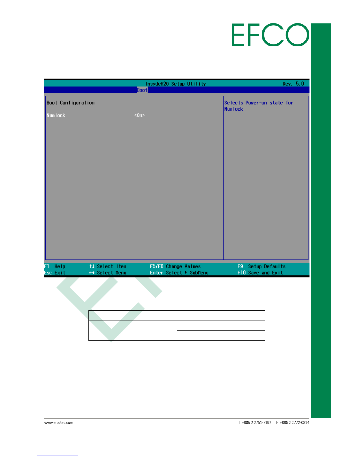
3.7.5.2 Boot Configuration
Photo_64 – Boot_Boot Configuration Setting
Numlock: Selects Power-on state for Numlock.
Function Item
Select Item_1
Numlock
Off
On (Default setting)
Table_45 – Boot_Boot Configuration Setting
Page 77

67
SmartEC Embedded Box PC
EBC-3330
3.7.6 Exit
Photo_65 – Exit Configuration
Exit Saving Changes: Exit system setup and save your changes (Hot Key: F10).
Save Change Without Exit: Save your changes and without exiting system.
Exit Discarding Changes: Exit system setup and without saving your changes.
Load Optimal Defaults: Load Optimal Defaults (Hot Key: F9).
Load Custom Defaults: Load Custom Defaults
Save Custom Defaults: Save Custom Defaults
Discard Changes: Discard Changes
Page 78

68
SmartEC Embedded Box PC
EBC-3330
Chapter 4
DRIVER INSTALLATION
Page 79

69
SmartEC Embedded Box PC
EBC-3330
4.1 Driver Installation
The EBC-3330 comes with a product DVD. That contains user's manual and all drivers
to help your setup product. Insert the DVD and follow the steps in the auto run
program to install the drivers.
In case the program does not start, follow the sequence below to install the drivers.
Step 1 – Install Chipset Driver
1. Open the “STEP1 – 01.Chipset” folder followed by “SetupChipset.exe”.
2. Follow the instructions.
3. Drivers will be installed automatically.
Step 2 – Install Graphic Driver
1. Open the “STEP2 – 02.Graphic” folder and select your OS.
2. Open the “Setup.exe” file in the folder.
3. Follow the instructions.
4. Drivers will be installed automatically.
Step 3 – Install Audio Driver
1. Open the “STEP3 – 03.Audio” folder followed by “Setup.exe”.
2. Follow the instructions.
3. Drivers will be installed automatically.
Step 4 –Install LAN Driver
1. Open the “STEP4 – 04.LAN” folder followed by “Autorun.exe”.
2. Follow the instructions.
3. Drivers will be installed automatically.
Step 5 – Install IO Driver
1. Open the “STEP5 – 05.IO Driver” folder and select your OS setup file.
2. Follow the instructions.
3. Drivers will be installed automatically.
Step 6 – Install TXE Driver
1. Open the “STEP6 – 06.TXE Driver” folder and select CPU type folder.
2. Open the “SetupTXE.exe” file in the folder.
3. Follow the instructions.
4. Drivers will be installed automatically.
Page 80

70
SmartEC Embedded Box PC
EBC-3330
Step 7 – Install MBI Driver (Windows 8 only, Optional)
1. Open the “STEP7 – 07.MBI Driver” folder followed by “Setup.exe”.
2. Follow the instructions.
3. Drivers will be installed automatically.
Step 8 – Install USB 3.0 Driver (Windows 7 only)
1. Open the “STEP8 – 08.USB30” folder followed by “Setup.exe”.
2. Follow the instructions.
3. Drivers will be installed automatically.
FOR OPTIONAL ACCESSORIES
Step 9 – Install COM Port Device Driver
1. Open the “STEP9 – 09.IOM-SERIAL” folder followed by “X rusbser_ver2200
_installer.exe”.
2. Follow the instructions.
3. Drivers will be installed automatically.
4. That will add COM3 to COM6 ports in device manager.
Photo_66 – COM Port Device
Step 10 – Install Ethernet Port Device Driver
System LAN Driver will include it.
Step 11 – Install USB 3.0 Port Device Driver
1. Open the “STEP11 – 11.IOM-USB30” folder followed by “Texas_Insturments
_xHCI_Driver_v1.16.5.0_Multilanguage_WHQL.exe”.
2. Follow the instructions.
3. Drivers will be installed automatically.
4. That will add COM3 to COM6 ports in device manager.
Step 12 – Install GPIO Port Driver
Windows OS will include driver.
Page 81

71
SmartEC Embedded Box PC
EBC-3330
Chapter A
OPTIONAL ACCESSORIES
Page 82

72
SmartEC Embedded Box PC
EBC-3330
A.1 Option Accessories I/O Indication
A.1.1 COM Port I/O (P/N: EFCP1169X1-L)
4 RS-232/422/485 ports of the COM Port I/O device.
Photo_67 – COM Port I/O Connector
Pin
Signal Name
Pin
Signal Name
1
DCD
2
RD(Rx)
3
TD(Tx)
4
DTR
5
GND
6
DSR
7
RTS
8
CTS
9
RI
Table_46 – LAN Pin Assignments Photo_68 – COM Port I/O Pin
Jumper location and Port define of the COM Port I/O Board.
Photo_69 – COM Port Jumper
Photo_70 – COM Port Define
Page 83

73
SmartEC Embedded Box PC
EBC-3330
COM Port Jumper Setting for RS-232/422/485.
Table_47 – COM Port Jumper Setting
4.1.2 Ethernet Port I/O (P/N: EFCP1168X1-L)
3 10/100/1000 LAN ports of the Ethernet Port I/O device.
Photo_71 – LAN Port I/O Connector
Pin
Signal Name
Pin
Signal Name
1
TX+, MDI0+
2
TX-, MDI0-
3
RX+, MDI1+
4
MDI2+
5
MDI2-
6
RX-, MDI1-
7
MDI3+
8
MDI3-
Table_48 – LAN Pin Assignments Photo_72 – Ethernet Connector
LAN1 LED State Table
Page 84

74
SmartEC Embedded Box PC
EBC-3330
LAN LED Status
LED1 (Link)
LED2 (SPEED)
Network link is not established or system
power off
Amber/ Blinking
OFF
10 Mbps (10 Base-T)
10 Full Duplex
Amber
OFF
Link/Active
Blinking
OFF
100 Mbps (100 Base-TX)
100 Full Duplex
Amber
Green
Link/Active
Blinking
ON
1000 Mbps (1000 Base-T)
1000 Full Duplex
Amber
Orange
Link/Active
Blinking
ON
Table_49 – LAN1 LED State
4.1.3 GPIO Port I/O (P/N: EFCP1170X1-L)
2 ports of the GPIO Port I/O device.
Photo_73 – GPIO Port I/O Connector
GPIO 1 = DATA OUTPUT. & GPIO 2 = DATA INPUT.
4.1.4 USB 3.0 Port I/O (P/N: EFCP1171X1-L)
4 USB3.0 ports of the USB Port I/O device.
Photo_74 – USB 3.0 Port I/O Connector
Page 85

75
SmartEC Embedded Box PC
EBC-3330
Pin
Signal Name
Pin
Signal Name
1
+5VSB
2
USB0_D-
3
USB0_D+
4
GND
5
USB1_SSRX-
6
USB1_SSRX+
7
GND
8
USB1_SSTX-
9
USB1_SSTX+
10
+5VSB
11
USB1_D-
12
USB1_D+
13
GND
Table_50 – USB3.9 Pin Assignments Photo_75 – USB 3.0 Port I/O
Page 86

76
SmartEC Embedded Box PC
EBC-3330
Chapter B
WATCHDOG TIMER INFORMATION
Page 87

77
SmartEC Embedded Box PC
EBC-3330
B.1 Watchdog Timer Initial Program
CR F0h. Watchdog Timer I(WDT1) and KBC P20 Control Mode Register
Location: Address F0h
Attribute: Read/Write
Power Well: VCC
Reset by: LRESET# or PWROK
Default: 00h
Size: 8 bits
BIT
READ / WRITE
DESCRIPTION
7-5
Reserved.
4
R / W
Watchdog Timer I count mode is 1000 times faster.
0: Disable.
1: Enable.
(If bit-3 is 0, the count mode is 1/1000 seconds mode.)
(If bit-3 is 1, the count mode is 1/1000 minutes mode.)
3
R / W
Select Watchdog Timer I count mode.
0: Second Mode.
1: Minute Mode.
2
R / W
Enable the rising edge of a KBC reset (P20) to issue a timeout event.
0: Disable.
1: Enable.
1
R / W
Disable / Enable the Watchdog Timer I output low pulse to
the KBRST# pin (PIN59)
0: Disable.
1: Enable.
0
Reversed
Table_51 – CR F0h. Watchdog Timer I(WDT1) and KBC P20 Control Mode Register
CR F1h. Watchdog Timer I(WDT1) Counter Register
Location: Address F1h
Attribute: Read/Write
Power Well: VCC
Reset by: LRESET# or PWROK
Default: 04h
Page 88

78
SmartEC Embedded Box PC
EBC-3330
Size: 8 bits
BIT
READ / WRITE
DESCRIPTION
7-0
R / W
Watch Dog Timer I Time-out value. Writing a non-zero value
to this register causes the counter to load the value into the
Watch Dog Counter and start counting down. If CR F2h, bits
7 and 6 are set, any Mouse Interrupt or Keyboard Interrupt
event causes the previously-loaded, non-zero value to be
reloaded to the Watch Dog Counter and the countdown
resumes. Reading this register returns the current value in
the Watch Dog Counter, not the Watch Dog Timer Time-out
value.
00h: Time-out Disable
01h: Time-out occurs after 5.03x10⁷ CLKIN cycle time, by
analogy. (5.03x107x (1/48MHz) = 1.046s)
Table_52 – CR F1h. Watchdog Timer I(WDT1) Counter Register
CR F2h. Watchdog Timer I(WDT1) Control & Status Register
Location: Address F2h
Attribute: Read/Write
Power Well: VCC
Reset by: LRESET# or PWROK
Default: 00h
Size: 8 bits
BIT
READ / WRITE
DESCRIPTION
7
R / W
Mouse interrupt reset enables watch-dog timer reload
0: Watchdog Timer I is not affected by mouse interrupt.
1: Watchdog Timer I is reset by mouse interrupt.
6
R / W
Keyboard interrupt reset enables watch-dog timer reload
0: Watchdog Timer I is not affected by keyboard interrupt.
1: Watchdog Timer I is reset by keyboard interrupt.
5
Write “1” Only
Trigger Watchdog Timer I event. This bit is self-clearing.
4
R / W
Write “0” Clear
Watchdog Timer I status bit
0: Watchdog Timer I is running.
1: Watchdog Timer I issues time-out event.
3-0
R / W
These bits select the IRQ resource for the Watchdog Timer I
Table_53 – CR F2h. Watchdog Timer I(WDT1) Control & Status Register
Page 89

79
SmartEC Embedded Box PC
EBC-3330
B.2 Watchdog Sample Program
#define SIO_Logical_Device_Selection 0x07;
#define SIO_Configuration_Register_30 0x30;
#define SIO_Configuration_Register_F0 0xF0;
#define SIO_WDT1_Counter_Register 0xF1;
#define BIT0 0x00000001;
//
// Choose the corresponding Index port value to access right Super I/O
//
UINT16 mSIOChipIndex [] = {0x2E, 0x4E, 0x162E, 0x164E};
void
IOWriteByte (word Register, byte Value) {
// Access IO port to write byte into Register
}
byte
IOReadByte (word Register) {
// Access IO port to read byte from Register
}
void
EnterConfigurationRegister (void) {
// Enter the Extended Function Mode
// Please refer SIO specification about "CONFIGURATION REGISTER ACCESS
PROTOCOL"
}
void
ExitConfigurationRegister (void) {
// Exit the Extended Function Mode
// Please refer SIO specification about "CONFIGURATION REGISTER ACCESS
PROTOCOL"
}
Page 90

80
SmartEC Embedded Box PC
EBC-3330
void SIOEnableWDT (void) {
UINT8 Data;
UINT16 SIOIndexPort = mSIOChipIndex [x];
UINT16 SIODataPort = SIOIndexPort + 1;
EnterConfigurationRegister ();
////////////////////////////////////////////////////////////////
//
// The following data and register refer to Logical Device about WDT1
//
////////////////////////////////////////////////////////////////
//
// Select logic device
//
IOWriteByte(SIOIndexPort, SIO_Logical_Device_Selection);
IOWriteByte(SIODataPort, Logical_Device_Number);
//
// WDT device enable
//
IOWriteByte(SIOIndexPort, SIO_Configuration_Register_30);
Data = IOReadByte(SIODataPort);
IOWriteByte(SIODataPort, (Data & BIT0)); // bit 0: Enable/Disable WDT
//
// Set WDT mode to seconds or minutes or more faster
//
IOWriteByte(SIOIndexPort, SIO_Configuration_Register_F0);
IOWriteByte(SIODataPort, WDT1_Count_Mode); //reference SIO Spec for more
info
//
// Set WDT base timer
//
IOWriteByte(SIOIndexPort, SIO_WDT1_Counter_Register);
Page 91

81
SmartEC Embedded Box PC
EBC-3330
IOWriteByte(SIODataPort, WDT1_Base_Timer); //reference SIO Spec for more
info
ExitConfigurationRegister ();
}
//******************************************************************//
//
// The following code is for disable WDT device
//
//******************************************************************//
void SIODisableWDT (void) {
UINT16 SIOIndexPort = mSIOChipIndex [x];
UINT16 SIODataPort = SIOIndexPort + 1;
EnterConfigurationRegister ();
//
// Select logic device
//
IOWriteByte(SIOIndexPort, SIO_Logical_Device_Selection);
IOWriteByte(SIODataPort, Logical_Device_Number);
//
// WDT device disable
//
IOWriteByte(SIOIndexPort, SIO_Configuration_Register_30);
Data = IOReadByte(SIODataPort);
IOWriteByte(SIODataPort, (Data & (~BIT0))); // bit 0: Enable/Disable WDT
ExitConfigurationRegister ();
}
Page 92

82
SmartEC Embedded Box PC
EBC-3330
Chapter C
I/O INFORMATION
Page 93

83
SmartEC Embedded Box PC
EBC-3330
C.1 I/O Address Map
Photo_76 – I/O address map
Page 94

84
SmartEC Embedded Box PC
EBC-3330
C.2 IRQ Mapping Chart
Photo_77 – IRQ Mapping Chart_1
Page 95

85
SmartEC Embedded Box PC
EBC-3330
Photo_78 – IRQ Mapping Chart_2
Page 96

86
SmartEC Embedded Box PC
EBC-3330
Photo_79 – IRQ Mapping Chart_3
Page 97

87
SmartEC Embedded Box PC
EBC-3330
C.3 Memory Address Map
Photo_80 – Memory address map
 Loading...