

Page 1
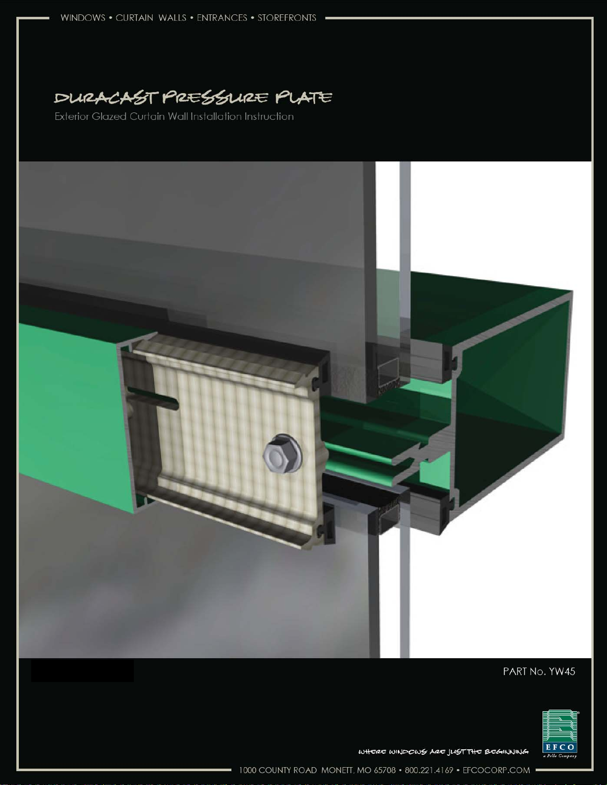
Duracast Pressure Plate Installation Instructions
December 2011
EFCO CORPORATION 12/5/2011 PART NO. YW45
Page 2

Duracast Pressure Plate Installation Instructions
TABLE OF CONTENTS
S-5600 / S-5900 DURACAST PRESSURE PLATE
SECTION PAGE
I. General Notes and Guidelines…………………………………………. 3-4
II. Glazing Preparation & Installation…………………………..………. 5
III. Pressure Plate Installation……………………………………..………. 6-10
IV. Vertical Splice Joints………………………………………………………. 11
V. Exterior Cover Installation…………...………………………………… 12
Minimizing Condensation
Note: Please reference EFCO's "Understanding Condensation" brochure which can be obtained
through your EFCO representative.
Condensation will form on any surface when unfavorable conditions (interior temperature and
relative humidity and exterior temperature) are present. When the formation of excessive condensation
is a concern, it is highly recommended that a design professional is utilized to perform an analysis of
the shop drawings to recommend the best possible installation methods. Please contact your EFCO
representative for information on EFCO's Thermal Analysis Services.
Many current installation practices lead to an increase in the possibility of the formation of
condensation. Though not all inclusive, the list of examples below illustrates conditions under which
condensation is likely to occur:
1. Bridging system thermal break with non-thermally broken metal flashing or lintels that
are exposed to the exterior
2. System exposure to cold air cavities
3. Interior relative humidity levels not maintained at recommended levels, see EFCO’s
“Understanding Condensation” brochure
4. Inadequate separation between system and surrounding condition at perimeter
5. Product combinations during the shop drawing stage that result in bridging thermal
breaks of one or all products involved
Note: These installation instructions are a supplement to the approved final shop
drawings and are to be used in conjunction with those drawings.
EFCO CORPORATION 6/2012 PART NO. YW45
2
Page 3

Duracast Pressure Plate Installation Instructions
Section I: General Notes and Guidelines
I. HANDLING / STORING / PROTECTING DURACAST - The following precautions are
recommended to assure early acceptance of your products and workmanship.
A. HANDLE CAREFULLY - Store with adequate separation between components so
the material will not rub together. Store the material off the ground. Protect materials against weather elements and other construction trades.
B. KEEP MATERIAL AWAY FROM WATER, MUD, AND SPRAY - Prevent cement,
plaster, and other materials from contacting with and damaging the finish. Do not
allow moisture to be trapped between the finished surface and the wrapping material.
C. PROTECT MATERIALS AFTER ERECTION - Wrap or erect screens of plastic
sheeting over material. Cement, plaster, terrazzo, and other alkaline materials are
very harmful to the finish and are to be removed with soap and water before hardening. Under no circumstances should these materials be allowed to dry or permanent staining will occur.
D. CUTTING OF DURACAST - Duracast can be cut with a standard miter saw using
a carbide blade; however, the life of the blade life will be shortened significantly
due to the high glass content of Duracast. For best results use a diamond tipped
or concrete blade for extended blade life.
II. GENERAL GUIDELINES - The following practices are recommended for all installations:
A. REVIEW APPROVED SHOP DRAWINGS – Become thoroughly familiar with the
project. Shop drawings govern when conflicting information exists in these installation instructions.
B. INSTALL ALL FRAMING MATERIAL PLUMB, LEVEL, AND TRUE – Proper
alignment and relationships to benchmarks and column centerlines, as established
by the architectural drawings and the general contractor, must be maintained.
C. The sequence of erection should be coordinated with the project superintendent to
prevent delays and minimize the risk of material damage. Note: If preset an-
chors are required, coordinate and supervise anchor placement with the
general contractor.
D. Verify that all job site conditions and accompanying substrates receiving the instal-
lation are in accordance with the contract documents. If deviations occur, notification must be given IN WRITING to the general contractor and differences resolved before proceeding further with the installation in the questionable area.
EFCO CORPORATION 6/2012 PART NO. YW45
3
Page 4

Duracast Pressure Plate Installation Instructions
SECTION I: GENERAL NOTES and GUIDELINES
F. Follow EFCO framing installation and glazing instructions.
G. Verify contents of all material shipments received upon their arrival. Verify quantity
and correct finishes. NOTIFY EFCO IMMEDIATELY OF ANY DISCREPANCIES
OR DAMAGE THAT MAY HAVE OCCURRED.
H. Throughout these instructions the term “SEALANT” will appear. For the purposes of
these instructions, sealant is to be defined as the following:
SEALANT - A weather resistant, gunnable liquid filler which when cured provides a
resilient, flexible (± 50% movement capability) air and water seal between similar
and dissimilar materials.
All sealant must meet ASTM C 920, CLASS 50.
BUTYL SEALANT- A non-skinning, non-hardening material (NAAMM Reference Standard 5C-1).
NOTE: All sealant must be compatible with all surfaces on which adhesion is re-
quired, including other sealant surfaces. All frame surfaces should be clean,
dry, dust, and frost free. If a primer is required, it must be applied to clean
surfaces. All perimeter substrates shall be clean and properly treated to receive sealant.
This system is designed and has been tested to utilize butyl or silicone sealants at all internal joineries, i.e., joint plugs, gasket intersections, etc.
Regardless of the sealant used, the customer should contact the sealant
manufacturer to determine compatibility and adhesion. Follow sealant manufacturer's proper application procedures and quality assurance programs for
weather sealing.
Maintain caulk joints as shown in the approved shop drawings. Unless
specified otherwise, most sealant manufacturers recommend a 3/8” minimum perimeter caulk joint. A 3/4” minimum joint is recommended at the
head condition to accommodate thermal expansion and contraction.
Anchoring surfaces of perimeter construction must be level and plumb within
the adjustable limits of the head, jamb, and sill framing.
EFCO CORPORATION 6/2012 PART NO. YW45
4
Page 5

Duracast Pressure Plate Installation Instructions
Section II: Glazing Prep. & Installation
Note: All anchors must be “FIXED” before glazing installation begins.
5600 Series — Outside Glazed Installation
A. Seal and install Joint plugs per Installation Instruction
Preparation
B.
Install Setting Blocks, Infill Glazing Material, Temporary Retainers, and Side Blocks per
Installation Instruction
. DO NOT install a Thermal Isolator as indicated in Steps 1A and 1B.
Y302 - Section VII: Glazing Installation, Steps #3 thru #5.
5900 Series — Outside Glazed Installation
A. Seal and install Joint plugs per Installation Instruction
cation.
B. Install Glazing Adaptors / Mullion Gaskets per Installation Instruction
Glazing Adaptors / Mullion Gaskets.
C.
Install Setting Blocks, Infill Glazing Material, and Anti-Walk Blocks ONLY per Installation
Instruction
Gaskets
Plate. See
Y350 - Sections VIII: Setting Blocks / Anti-Walk Blocks / Pressure Plate
. Follow the instructions in this document for the installation of the Pressure
Section III - Pressure Plate Installation
Y302 - Section VI: Glazing
Y350 - Sections VI: Joint Plug Appli-
Y350 - Sections VII:
EFCO CORPORATION 6/2012 PART NO. YW45
5
Page 6

Duracast Pressure Plate Installation Instructions
Section III: Pressure Plate Installation
Note: All anchors must be “FIXED” before glazing installation begins.
STEP #1 Perimeter Pressure Plate Preparation
A. If not using a Perimeter Adaptor skip to Step #2
B. Align the Perimeter Adaptor the Pressure plate and install using a rubber
mallet or hammer every 2 to 3 feet. The adaptor should be installed flus h
with each end of the pressure Plate.
C. When installing the exterior gasket material as described in step #2, one
gasket should be installed in the pressure plate and the second gasket
installed in the Perimeter Adaptor.
Install Perimeter adaptor with
mallet every 2 to 3 feet.
Align Perimeter adaptor to pressure
plate. The Pressure Plate and
Adaptor should both be flush at the
each end.
Install glazing gaskets per step
#2. One gasket should be
located in the adaptor and one
in the pressure plate
EFCO CORPORATION 6/2012 PART NO. YW45
6
Page 7

Duracast Pressure Plate Installation Instructions
Section III: Pressure Plate Installation
Note: All anchors must be “FIXED” before glazing installation begins.
STEP #2 Pressure Plate Preparation
A. Remove exterior gasket material from the reel and allow to relax and
shrink.
B. Insert glazing gaskets into the pressure plates. For horizontals, gaskets
should extend 1/4” beyond each end of the pressure plate. For vertical
single story applications, gaskets should be flush with both ends of the
pressure plate. For vertical multi-story applications, gaskets should extend
1” beyond the top end of the pressure plate and flush with the bottom end
of the pressure plate.
Horizontal Pressure Plate
Horizontal Pressure Plate
Vertical Pressure
Plate
Typical horizontal gasket
extended ¼” each end.
Typical horizontal gasket
extended ¼” each end.
STEP #3 Joint Plug Face Sealing
A. Apply sealant to the face of
the joint plugs prior to installation of vertical and horizontal pressure plates.
Typical vertical
gasket cut flush
top and bottom.
Vertical at multistory, gasket
extended 1” at
top only
Apply sealant to face
of all joint plugs
EFCO CORPORATION 6/2012 PART NO. YW45
7
Page 8

Duracast Pressure Plate Installation Instructions
Section III: Pressure Plate Installation
STEP #4 Install Pressure Plate
A. First attach the vertical pressure plates and then the horizontal pressure
plates into position using stainless steel hex washer head screws (refer to
Table #1 for screw size based on Curtain Wall Series). Locate screws in
the first complete pre-punched hole
on each end of the pressure plate no
more than 3.5” from the end. Refer
to the final approved shop drawings
for screw spacing.
B. Torque screws to 80 inch-pounds.
C. In cold Weather, first torque all
pressure plate screws to 40 inch-
pounds. Once all four sides have
been clamped down, torque all
screws to 80 inch-pounds.
D. When possible, work from the center
outward on horizontals and from the
sill upward on verticals.
E. Glazier should always place screws in
pre-punched holes immediately above and below each horizontal. This will
provide maximum control of pressure on mullion plugs that provide a criti-
cal sealing function.
F. The pressure plate should extend 3” past any splice (see Section IV:
Vertical Splice Joints).
Pressure Plate End
Incomplete Hole
Hex washer head
screw in first
complete hole
(see Table #1).
Table #1
CurtainWall
Series ScrewSize&Type
5600 #13x5/8"S.S.HexWasherHeadScrew
5900 ¼"x1"S.S.HexWasherHeadScrew
Place screws in holes
immediately above and
below all horizontals
EFCO CORPORATION 6/2012 PART NO. YW45
8
Page 9

Duracast Pressure Plate Installation Instructions
Section III: Pressure Plate Installation
STEP #4 Install Pressure Plate (continued)
F. For curtain wall systems that utilize vertical covers 1” in depth and over,
attach a Roll Pin Support on the vertical
at each horizontal. This will allow the
application of a roll pen after cover
installation to prevent slippage.
G. For curtain wall systems that utilize
horizontal covers 1” in depth and over,
attach a Roll Pin Support at the
mid-span of the horizontal.
Roll Pin Support located
at each horizontal when
vertical cover depth 1”
and over.
Weep
Note: Orient horizontal pressure
plates such that the weeps are
located above the mullion tongue
Note: Horizontal pressure plates are
¼” shorter than horizontal mullions.
The glazier should center the horizontal
pressure plate on the mullion before
installation.
EFCO CORPORATION 6/2012 PART NO. YW45
9
Page 10

Duracast Pressure Plate Installation Instructions
Section III: Pressure Plate Installation
STEP #5 Seal Pressure Plate Ends
A. Seal all joints between the vertical and horizontal pressure plates with
sealant to provide a water and airtight joint.
Seal joint between
horizontal and vertical
pressure plates.
EFCO CORPORATION 6/2012 PART NO. YW45
10
Page 11

Duracast Pressure Plate Installation Instructions
5600 Series — Outside Glazed Installation
5900 Series — Outside Glazed Installation
Section IV: Vertical Splice Joints
A. Vertical splices should be assembled per
Splice Joints
locations and overlaps.
A. Vertical splices should be assembled per
Joints
and overlaps.
including location of pressure plate and cover splice joint locations
including location of pressure plate and cover splice joint
Y302 - Section VIII: Vertical
Y350 - Section V: Vertical Splice
EFCO CORPORATION 6/2012 PART NO. YW45
11
Page 12

Duracast Pressure Plate Installation Instructions
5600 Series — Outside Glazed Installation
5900 Series — Outside Glazed Installation
Section V: Exterior Cover Installation
A. Vertical and horizontal covers should be installed per Installation Instruc-
tion
Y302 - Section IX: Exterior Cover Installation.
required they should be located such that the pins engage the
Roll Pin Supports applied in Section III, Step #3 of this
instruction.
A. Vertical and horizontal covers should be installed per Installation Instruc-
tion
Y350 - Section X: Exterior Cover Installation.
required they should be located such that the pins engage the
Roll Pin Supports applied in Section III, Step #3 of this
instruction.
Note, if roll pins are
Note, if roll pins are
EFCO CORPORATION 6/2012 PART NO. YW45
12
 Loading...