

Page 1

DS 2600 4S
(1.5 cu.in)
-
DS 3600 4S
(2.18 cu.in)
en
fr
es
OPERATOR’S INSTRUCTION MANUAL
MANUEL D’UTILISATION ET D’ENTRETIEN
MANUAL DE INSTRUCCIONES
Page 2
en
INTRODUCTION
To correctly use the brush cutter and prevent accidents, do not start work without having
first carefully read this manual. You will find explanations concerning the operation of the
various parts plus instructions for necessary checks and relative maintenance.
Note: Illustrations and specifications in this manual may vary according to
Country requirements and are subject to change without notice by the
manufacturer.
THE OPERATOR’S MANUAL
Your operator’s manual is for your protection. READ IT. Keep it in a safe place for
reference. Know what you are doing before you begin assembly of the unit. Proper
preparation and upkeep go hand-in-hand with satisfactory performance of the brush
cutter and safety.
Contact your dealer or the distributor for your area if you do not understand any of the
instructions in this manual.
In addition to the operating instructions, this manual contain paragraphs that require
your special attention.
Such paragraphs are marked with the symbols described below:
Warning: where there is a risk of an accident or personal injury or serious damage to
property.
Caution: where there is a risk of damaging the machine or its individual components.
WARNING - To ensure safe and correct operation of the
brush cutter, this operator's manual should always be kept with
or near the machine. Do not lend or rent your brush cutter
without the operator's instruction manual.
WARNING: Allow only persons who understand this manual to
operate your brush cutter.
2
Page 3

TABLE OF CONTENTS
PRODUCT IDENTIFICATION
Brush Cutter Components . . . . . . . . . . . . . . . . . . . . . . . . . . . . . . . . . . . . . . . . . . . . . . . . . . . . . . 4
SAFETY
Understanding Safety Symbols . . . . . . . . . . . . . . . . . . . . . . . . . . . . . . . . . . . . . . . . . . . . . . . . . .5
State and Local Requirements . . . . . . . . . . . . . . . . . . . . . . . . . . . . . . . . . . . . . . . . . . . . . . . . . . . 5
SAFETY RULES
Basic Safety Precautions . . . . . . . . . . . . . . . . . . . . . . . . . . . . . . . . . . . . . . . . . . . . . . . . . . . . . . . 7
Fuel Handling . . . . . . . . . . . . . . . . . . . . . . . . . . . . . . . . . . . . . . . . . . . . . . . . . . . . . . . . . . . . . . . . 8
Operation and Safety . . . . . . . . . . . . . . . . . . . . . . . . . . . . . . . . . . . . . . . . . . . . . . . . . . . . . . . . . . 8
Precautions Against Kickout . . . . . . . . . . . . . . . . . . . . . . . . . . . . . . . . . . . . . . . . . . . . . . . . . . . . . 9
Maintain Control . . . . . . . . . . . . . . . . . . . . . . . . . . . . . . . . . . . . . . . . . . . . . . . . . . . . . . . . . . . . . . 9
Safety Features . . . . . . . . . . . . . . . . . . . . . . . . . . . . . . . . . . . . . . . . . . . . . . . . . . . . . . . . . . . . . . 10
Recommended Cutting Attachments . . . . . . . . . . . . . . . . . . . . . . . . . . . . . . . . . . . . . . . . . . . . . . 10
Safety equipment checking . . . . . . . . . . . . . . . . . . . . . . . . . . . . . . . . . . . . . . . . . . . . . . . . . . . . . . 11
Precautions to Reduce Vibration Risk . . . . . . . . . . . . . . . . . . . . . . . . . . . . . . . . . . . . . . . . . . . . . 11
Maintenance Precautions . . . . . . . . . . . . . . . . . . . . . . . . . . . . . . . . . . . . . . . . . . . . . . . . . . . . . . . 11
en
ASSEMBLY
Fitting the loop handle . . . . . . . . . . . . . . . . . . . . . . . . . . . . . . . . . . . . . . . . . . . . . . . . . . . . . . . . . 13
Fitting the cutting attachment guard . . . . . . . . . . . . . . . . . . . . . . . . . . . . . . . . . . . . . . . . . . . . . . . 13
Assembling the cutting attachment . . . . . . . . . . . . . . . . . . . . . . . . . . . . . . . . . . . . . . . . . . . . . . . 13
OPERATION
Fueling . . . . . . . . . . . . . . . . . . . . . . . . . . . . . . . . . . . . . . . . . . . . . . . . . . . . . . . . . . . . . . . . . . . . . 15
Engine Oil Tank . . . . . . . . . . . . . . . . . . . . . . . . . . . . . . . . . . . . . . . . . . . . . . . . . . . . . . . . . . . . . . . 16
Preparation for Cutting . . . . . . . . . . . . . . . . . . . . . . . . . . . . . . . . . . . . . . . . . . . . . . . . . . . . . . . . . 16
Starting the Engine . . . . . . . . . . . . . . . . . . . . . . . . . . . . . . . . . . . . . . . . . . . . . . . . . . . . . . . . . . . . 18
High Altitude Operation . . . . . . . . . . . . . . . . . . . . . . . . . . . . . . . . . . . . . . . . . . . . . . . . . . . . . . . . 19
Breaking-in the Engine . . . . . . . . . . . . . . . . . . . . . . . . . . . . . . . . . . . . . . . . . . . . . . . . . . . . . . . . . 19
Stopping the Engine . . . . . . . . . . . . . . . . . . . . . . . . . . . . . . . . . . . . . . . . . . . . . . . . . . . . . . . . . . . 20
Working Techniques . . . . . . . . . . . . . . . . . . . . . . . . . . . . . . . . . . . . . . . . . . . . . . . . . . . . . . . . . . . 20
MAINTENANCE
Maintenance Chart . . . . . . . . . . . . . . . . . . . . . . . . . . . . . . . . . . . . . . . . . . . . . . . . . . . . . . . . . . . . 25
Cutting Attachment Maintenance . . . . . . . . . . . . . . . . . . . . . . . . . . . . . . . . . . . . . . . . . . . . . . . . .26
Carburetor Adjustment . . . . . . . . . . . . . . . . . . . . . . . . . . . . . . . . . . . . . . . . . . . . . . . . . . . . . . . . . 28
Fuel Filter . . . . . . . . . . . . . . . . . . . . . . . . . . . . . . . . . . . . . . . . . . . . . . . . . . . . . . . . . . . . . . . . . . . 28
Air Filter . . . . . . . . . . . . . . . . . . . . . . . . . . . . . . . . . . . . . . . . . . . . . . . . . . . . . . . . . . . . . . . . . . . . 28
Starter Unit . . . . . . . . . . . . . . . . . . . . . . . . . . . . . . . . . . . . . . . . . . . . . . . . . . . . . . . . . . . . . . . . . . 28
Engine . . . . . . . . . . . . . . . . . . . . . . . . . . . . . . . . . . . . . . . . . . . . . . . . . . . . . . . . . . . . . . . . . . . . . . 29
Spark Plug . . . . . . . . . . . . . . . . . . . . . . . . . . . . . . . . . . . . . . . . . . . . . . . . . . . . . . . . . . . . . . . . . . 29
Spark Arresting Muffler . . . . . . . . . . . . . . . . . . . . . . . . . . . . . . . . . . . . . . . . . . . . . . . . . . . . . . . . . 29
Bevel Gear . . . . . . . . . . . . . . . . . . . . . . . . . . . . . . . . . . . . . . . . . . . . . . . . . . . . . . . . . . . . . . . . . . 30
Guard . . . . . . . . . . . . . . . . . . . . . . . . . . . . . . . . . . . . . . . . . . . . . . . . . . . . . . . . . . . . . . . . . . . . . . 30
Oil Change . . . . . . . . . . . . . . . . . . . . . . . . . . . . . . . . . . . . . . . . . . . . . . . . . . . . . . . . . . . . . . . . . . 30
TROUBLESHOOTING
Using Troubleshooting Chart . . . . . . . . . . . . . . . . . . . . . . . . . . . . . . . . . . . . . . . . . . . . . . . . . . . . 31
STORAGE
Storing Brush cutter . . . . . . . . . . . . . . . . . . . . . . . . . . . . . . . . . . . . . . . . . . . . . . . . . . . . . . . . . . . 32
TECHNICAL DATA
DS 2600 4S . . . . . . . . . . . . . . . . . . . . . . . . . . . . . . . . . . . . . . . . . . . . . . . . . . . . . . . . . . . . . . . . . 32
DS 3600 4S . . . . . . . . . . . . . . . . . . . . . . . . . . . . . . . . . . . . . . . . . . . . . . . . . . . . . . . . . . . . . . . . . 32
3
Page 4
en
PRODUCT IDENTIFICATION
6
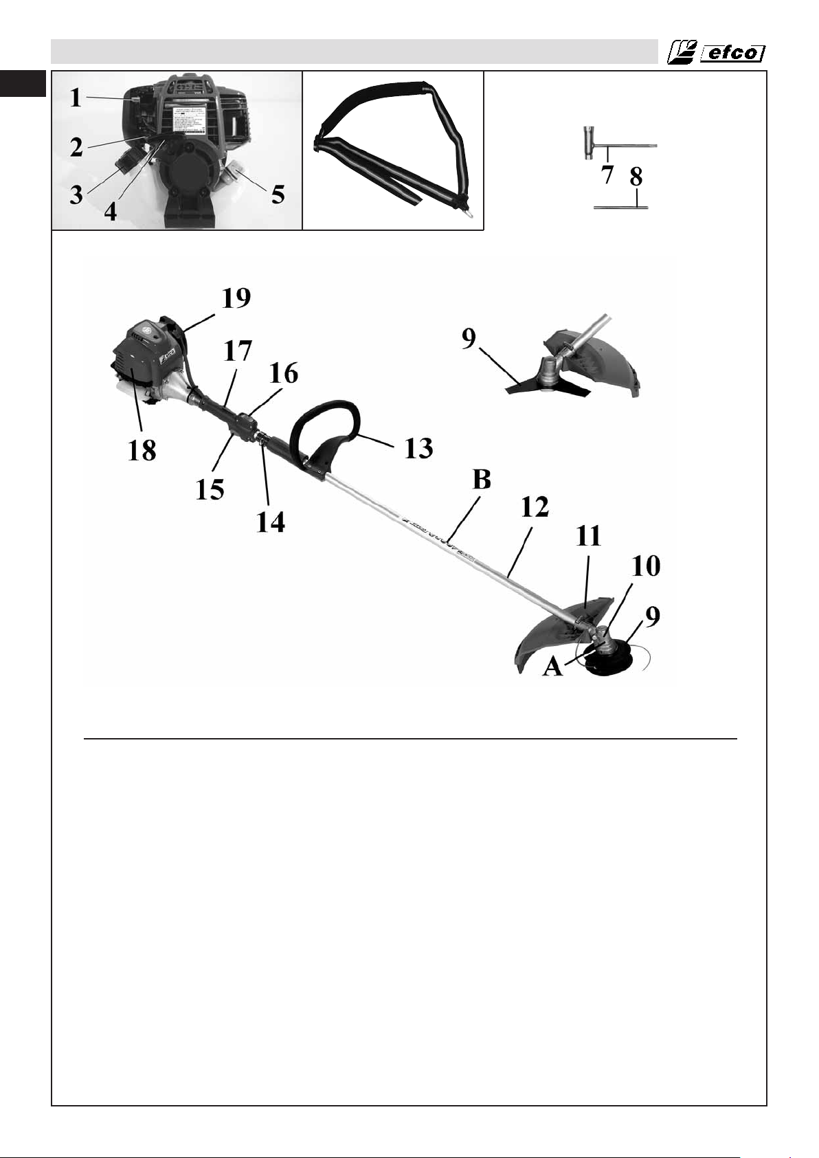
Brush Cutter Components
1 - Choke Lever
2 - Purge Bulb
3 - Fuel Tank Cap
4 - Starter Handle
5 - Oil Tank Cap
6 - Harness
7 - Combination Wrench
8 - Locking Pin
9 - Blade / Trimmer Head
10 - Bevel Gear
11 - Cutting Attachment Guard
12 - Shaft
4
13 - Loop Handle
14 - Harness attachment point
15 - Throttle Trigger
16 - On/Off Switch
17 - Throttle Trigger Lockout
18 - Muffler Cover
19 - Air Filter Cover
A - Safety warning: Cutting attachment
rotation speed
B - Safety warning: general instructions
C - Identification plate
Page 5

Understanding Safety Symbols
SAFETY
en
- This symbol indicates Warning,
and Caution.
- Your manual contains special
messages to bring attention to
potential safety concerns,
machine damage as well as
helpful operating and servicing
information. PLEASE READ ALL
THE INFORMATION CAREFULLY TO AVOID INJURY AND
MACHINE DAMAGE.
- Wear eye, hearing and head
protection when operating this
equipment.
- Wear non-slip, heavy-duty protective gloves when handling the
brush cutter and blades.
- Wear safety strong shoes or boots
having skid-proof sole and anti-piercing
insert.
- Be aware that objects can be
thrown.
- Keep bystanders away 50 ft (15 m).
- Max. speed of output shaft, RPM
- Do not use the brushcutter with the
wood cutting disk
State and Local Requirements
Your brush cutter is equipped with a temperature limiting muffler, a spark arresting screen in order to
comply with the requirements of SAE Recommended Practice J335 and California Codes 4442 and 4443.
All national forest land and land managed by the states of California, Maine, Washington, Idaho,
Minnesota, New Jersey and Oregon require internal combustion engines to be equipped with a
spark arrester screen by law. Other states and federal agencies are enacting similar regulations.
If you operate a brush cutter in a state or locale where such regulations exist, you are legally responsible
for maintaining the operating condition of these parts. Failure to do so is a violation of a law. Spark
arrester maintenance is described in the Maintenance-Spark Arresting Muffler Section of the
manual.
Note: When using a brush cutter for logging purposes, refer to Code of Federal Regulations, Parts
1910 and 1928.
WARNING: The ignition system of your unit produces an electromagnetic field of a very low
intensity. This field may interfere with some pacemakers. To reduce the risk of serious or
fatal injury, persons with pacemaker should consult their physician and the pacemaker
manufacturer before operating this tool.
WARNING: Muffler surfaces are very hot during and after operation of the brush cutter, keep
all body parts away from the muffler. Serious burns may occur if contact is made with the
muffler.
5
Page 6

en
SAFETY
WARNING: Exposure to vibrations through prolonged use of gasoline powered hand tools
could cause blood vessel or nerve damage in the fingers, hands, and wrists of people
prone to circulation disorders or abnormal swellings. Prolonged use in cold weather has
been linked to blood vessel damage in otherwise healthy people. If symptoms occur such
as numbness, pain, loss of strength, change in skin colour or texture, or loss of feeling in
the fingers, hands, or wrists, discontinue the use of this tool and seek medical attention.
WARNING: The engine exhaust from this product contains chemicals known to the State of
California to cause cancer, birth defects or other reproductive harm.
Operate your brush cutter outdoors only in a well ventilated area.
WARNING: Under no circumstances may the design of the machine be modified. Always use
genuine accessories. Non-authorized modifications and/or accessories can result in serious
personal injury or the death of the operator or others. Your warranty may not cover damage
or liability caused by the use of non-authorized accessories or replacement parts.
WARNING: A brush cutter or trimmer can be dangerous if used incorrectly or carelessly, and
can cause serious or fatal injury to the operator or others. It is extremely important that you
read and understand the contents of this operator’s manual.
6
Page 7
SAFETY RULES
Basic Safety Precautions
• Read this manual carefully until you completely understand and
can follow all safety rules, precautions, and operating
instructions before attempting to use the unit.
• Restrict the use of your brush cutter to adult users who
understand and can follow safety rules, precautions, and
operating instructions found in this manual. Minors should
never be allowed to use a brush cutter.
1
2
3
4
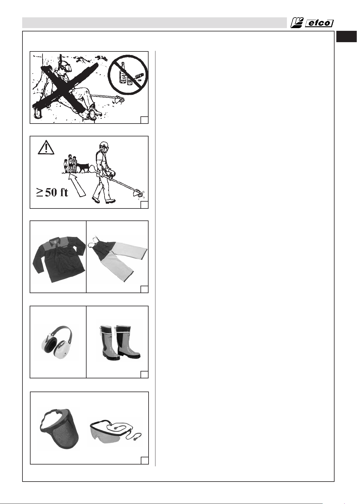
• Do not handle or operate a brush cutter when you are fatigued,
ill, or upset, or if you have taken alcohol, drugs, or medication.
You must be in good physical condition and mentally alert.
Brush cutter work is strenuous. If you have any condition that
might be aggravated by strenuous work, check with your doctor
before operating a brush cutter (Fig. 1). Be more cautious
before rest periods and towards the end of your shift.
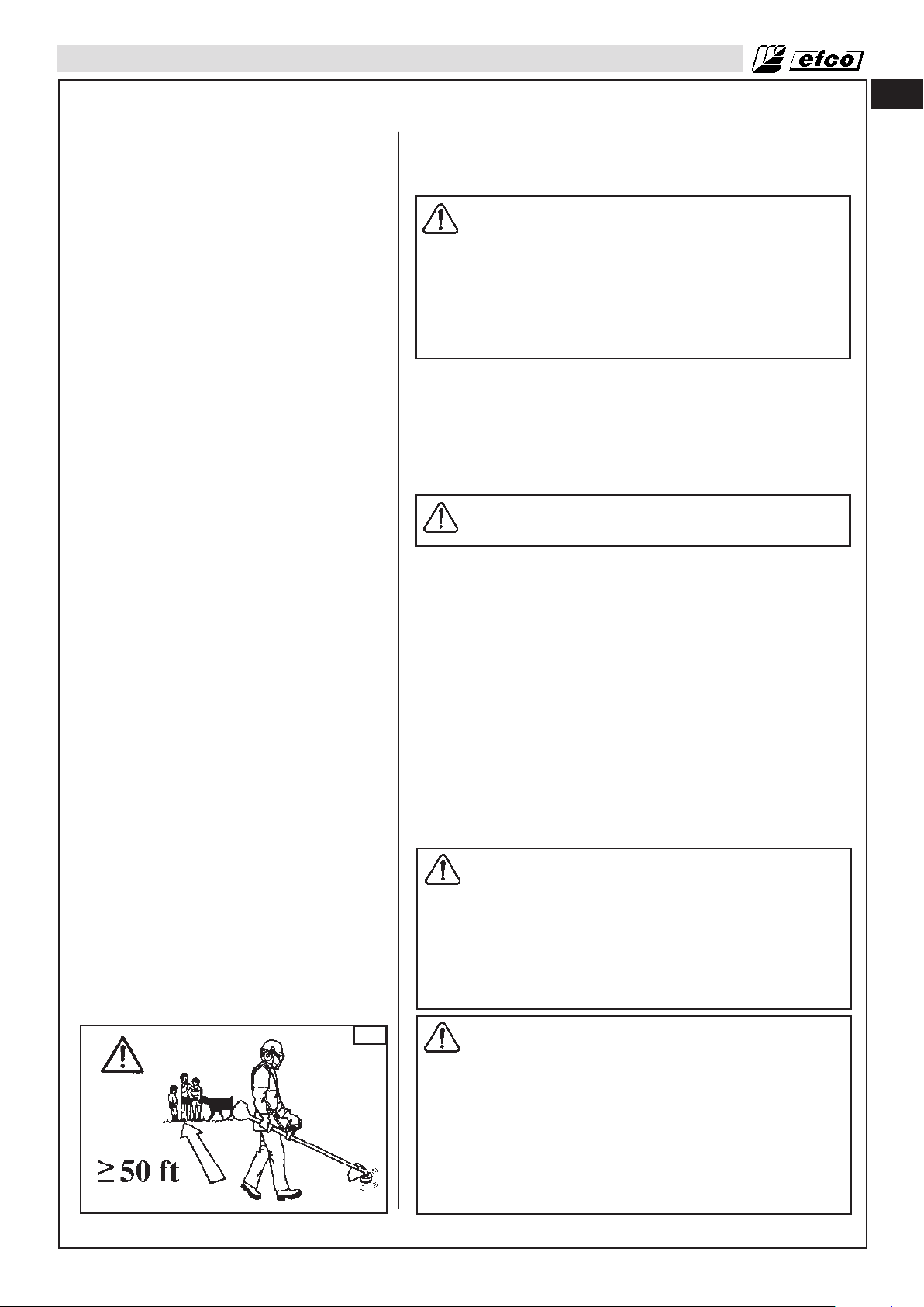
• Keep children, bystanders, and animals a minimum of 50 feet
(15 meters) away from the work area. Do not allow other
people or animals to be near the brush cutter when starting or
operating the brush cutter (Fig. 2).
• Major cases of brush cutter accidents happen when the blade
or thrown objects hits the operator. While working with the
brush cutter, always use safety protective approved clothing.
The use of protective clothing does not eliminate injury risks,
but reduces the injury effects in case of accident. Consult your
trusted supplier to choose equipment in compliance with
legislation. The clothing must be proper and not an obstacle.
Wear adherent protective clothing. Protective jackets (Fig.3)
and dungarees (Fig.3) leggings are ideal. Do not wear
clothes, scarves, ties or bracelets that may get stuck into twigs.
Tie up and protect long hair (example with foulards, cap,
helmets, etc.). Safety boots having skid-proof sole and
anti-piercing insert (Fig.4). Wear protective goggles or face
screens (Fig. 5). Use protections against noises: for
example, noise reduction ear guards (Fig.4) or earplugs.
The use of protections for the ear requires much more
attention and caution, because the perception of audible
warning signals (screaming, alarms, etc.) is limited. Always
remove your hearing protection as soon as the engine stops.
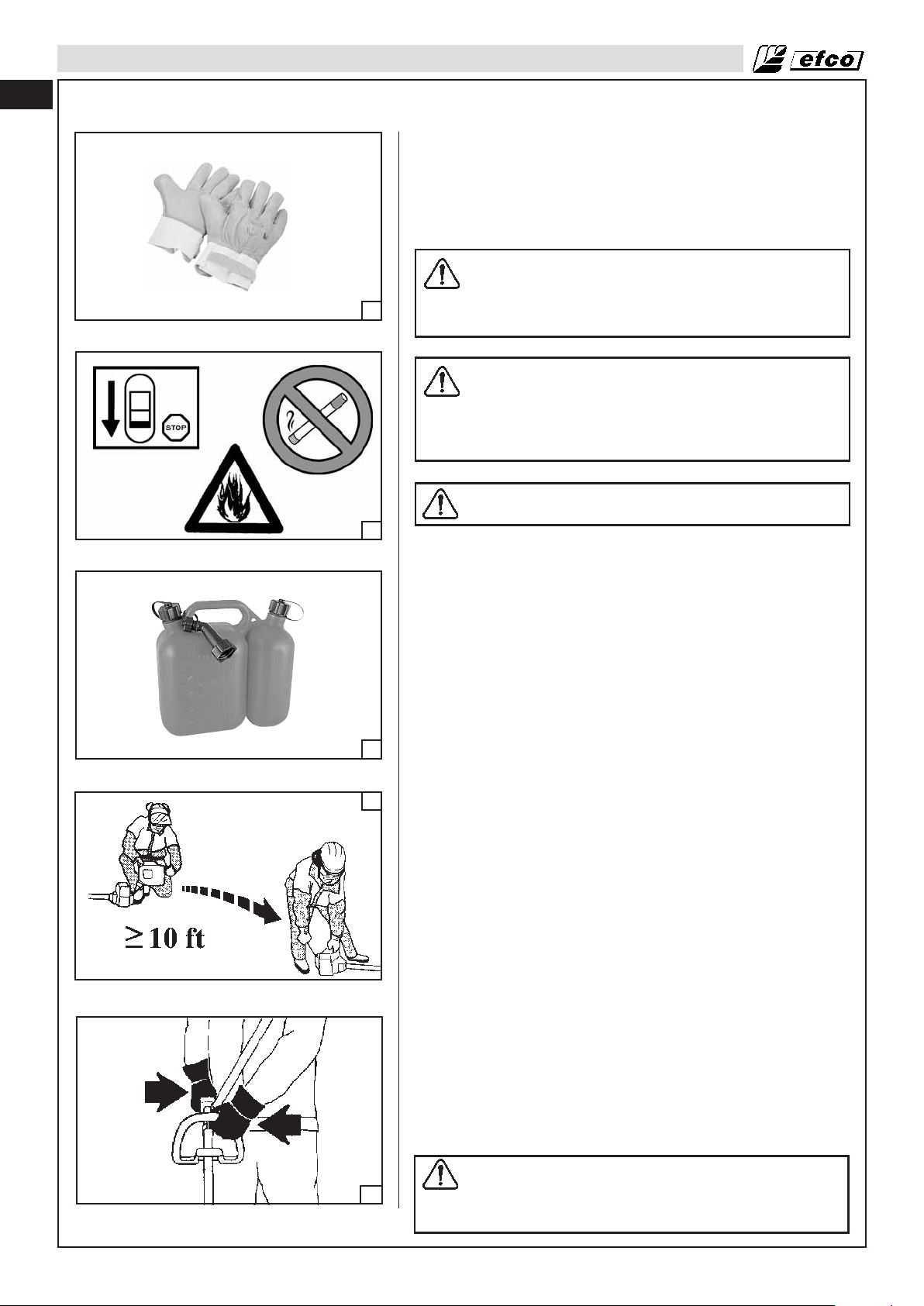
Wear gloves (Fig.6, page 8) that permit the maximum
absorption of vibrations.
• Only allow others to use this brush cutter who have read this
Operator’s Manual or received adeguate instructions for the
safe and proper use of this brush cutter.
• Check the brush cutter each day to ensure that each device,
whether for safety or otherwise, is functional.
• Never use a damaged, modified, or improperly repaired or
assembled brush cutter. Do not remove, damage or deactivate
any of the safety devices. Only use cutting tools indicated in the
table (page 10). Always replace cutting tools or safety devices
immediately if it becomes damaged, broken or is otherwise
removed.
• Carefully plan your operation in advance. Do not start cutting
until you have a clear work area, secure footing, and, if you are
felling trees, a planned retreat path.
• All brush cutter service, other than the operations shown in the
present manual, have to be performed by competent
personnel.
• The brush cutter must only be used for trimming grass, grass
clearing and / or forestry clearing. It is unadvisable to cut other
5
types of material.
en
7
Page 8
en
SAFETY RULES
• It is unadvisable to hitch tools or applications to the P.t.o. that
are not specified by the manufacturer.
Fuel Handling
WARNING: Gasoline is an extremely flammable fuel.
Use extreme caution when handling gasoline or fuel
6
mix. Do not smoke or bring any fire or flame near the
fuel or the brush cutter (Fig. 7).
WARNING: Fuel and fuel fumes can cause serious
injury when inhaled or allowed to come in contact
with the skin. For this reason observe caution when
handling fuel and make sure there is adequate
ventilation.
WARNING: Beware of carbon monoxide poisoning.
7
• To reduce the risk of fire and burn injury, handle fuel with
care. It is highly flammable.
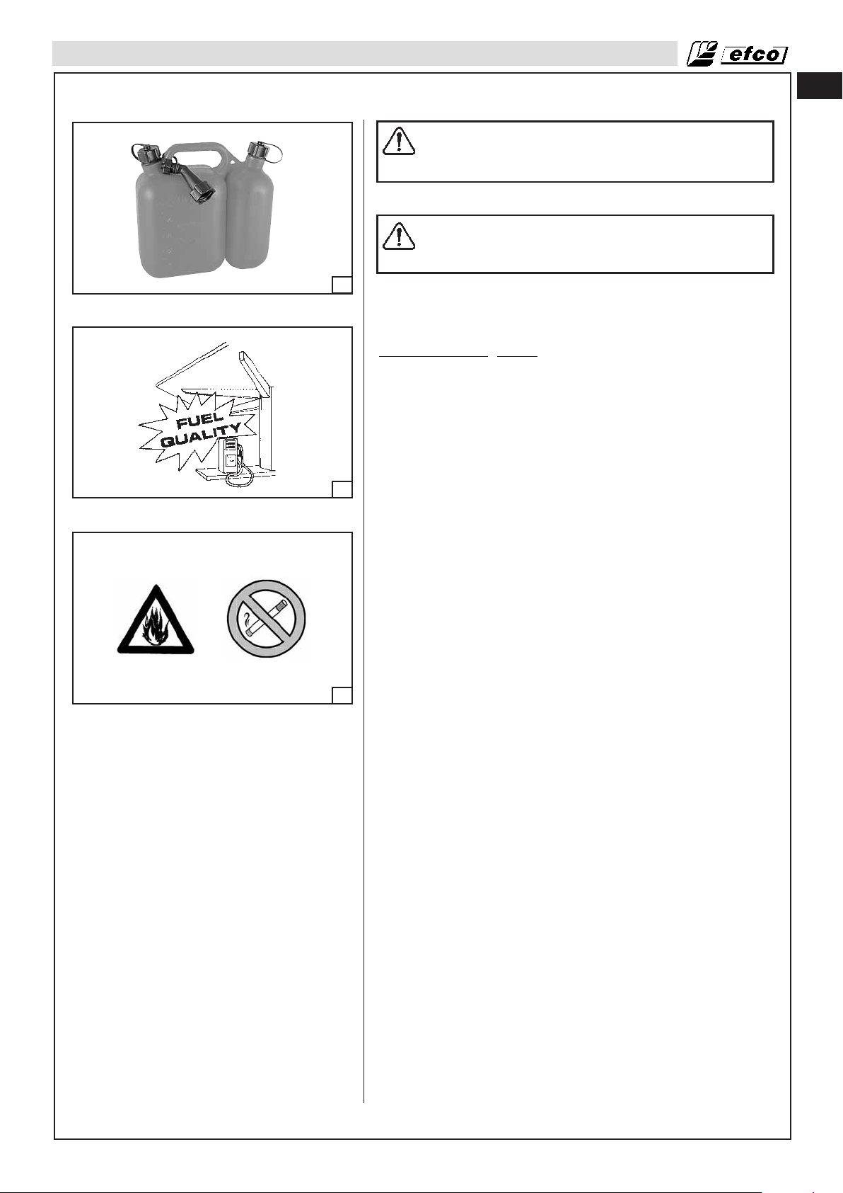
• Handle, store and transport fuel in a container approved for
gasoline (Fig. 8).
• Handle fuel outdoors where there are no sparks or flames.
• Select bare ground, stop engine, and allow to cool before
refuelling.
• Loosen fuel cap slowly to release pressure and to keep fuel
from escaping around the cap.
• Tighten fuel cap securely after refuelling. Unit vibration can
cause an improperly tightened fuel cap to loosen or come off
8
9
and spill quantities of fuel.
• Wipe spilled fuel from the unit and allow remaining fuel to
evaporate. Move 10 feet (3 m) away from refuelling site before
starting engine (Fig. 9).
• Never attempt to burn off spilled fuel under any circumstances.
• Do not smoke while handling fuel or while operating the brush
cutter.
• Store fuel in a cool, dry, well ventilated place.
• Never place the brush cutter in a combustible area such as dry
leaves, straw, paper, etc.
• Store the unit and fuel in an area where fuel vapors cannot
reach sparks or open flames from water heaters, electric
motors or switches, furnaces, etc.
• Never take the cap off the tank when the engine is running.
• Never use fuel for cleaning operations.
• Take care not to get fuel on your clothing. If you have spilt fuel
on yourself or your clothes, change your clothes. Wash any part
of your body that has come in contact with fuel. Use soap and
water.
• Don’t expose fuel tank to direct sunlight.
• Keep fuel out of reach of children.
Operation and Safety
WARNING: Always hold the brush cutter with both
10
hands when the engine is running. Use a firm grip
with thumbs and fingers encircling the brush cutter
handles (Fig. 10).
8
Page 9

SAFETY RULES
• Keep all parts of your body away from the cutting attachment
when the engine is running.
• Always carry the brush cutter with the engine stopped and the
muffler away from your body. When transporting your brush
cutter, use the appropriate blade guard (Fig. 11). When
transporting in a vehicle, keep blade covered with the guard.
Properly secure your brush cutter to prevent turnover, fuel
spillage and damage.
• Do not operate a brush cutter with one hand! Serious injury
to the operator, helpers, bystanders, or any combination of
11
12
these persons may result from one-handed operation. A brush
cutter is intended for two-handed use.
• Before you start the engine, make sure the cutting attachment
is not contacting any object.
• Shut off the engine before setting down the brush cutter. Do
not leave the engine running unattended.
• Only use the brush cutter in well-ventilated places, do not
operate the brush cutter in explosive or flammable
atmospheres or in closed environments (Fig. 12). Beware of
carbon monoxide poisoning.
• Do not operate brush cutter from a ladder or in a tree. Always
cut from a firm-footed and safe position.
WARNING: Take great care when working on sloping
ground.
• Do not cut near electric cables.
• Keep the handles dry, clean, and free of oil or fuel.
• Never cut with the brush cutter above shoulder height (Fig. 13).
• Never use the brush cutter without blade guard or the head.
• Do not start the engine with the arm not mounted.
en
13
14
15
Precautions Against Kickout
WARNING: Avoid kickout which can result in serious
injury. Kickout is the sideward, or sudden forward
motion of the machine occurring when the blade
contacts any object such as a log or stone, or when
the wood closes in and pinches the saw blade in the
cut. Contacting a foreign object can also result in
loss of brush cutter control.
Reduce the Risk of Kickout
WARNING: Recognize that kickout can happen. With a
basic understanding of kickout, you can reduce the
element of surprise which contributes to accidents.
• Never let the moving blade contact any object.
• Keep the working area free from obstructions such as other
trees, branches, rocks, fences, stumps, etc. Eliminate or avoid
any obstruction that your blade could hit while you are cutting.
• Keep your blade sharp. Follow manufacturer’s blade
sharpening and maintenance instructions.
• Begin and continue cutting at full speed. If the blade is moving
at a slower speed, there is greater chance of kickout
occurring.
Maintain Control (Fig.14-15)
• Keep a good, firm grip on the brush cutter with both hands
when the engine is running and don’t let go. A firm grip will help
you reduce kickout and maintain control of the brush cutter.
Keep the fingers encircling the handle.
• Stand with your weight evenly balanced on both feet.
• Do not overreach. You could be drawn or thrown off balance
and lose control of the brush cutter.
9
Page 10
en
SAFETY RULES
Safety Features
WARNING: As a brush cutter user, do not solely rely on the product’s safety features. You
must follow all safety precautions, instructions, and maintenance in this manual to help avoid
serious injury.
WARNING: Even with proper maintenance, the correct operation of the safety features under
field conditions can not be certified.
• Position of handle, designed with distance between handles and with each other. The spread and position
of the hands provided by this design work together to give balance and resistance in controlling the
machine.
Recommended cutting attachments
1
2
3
4
5
6
7
8
9A
9B
10A
10B
11A
11B
12A
12B
13
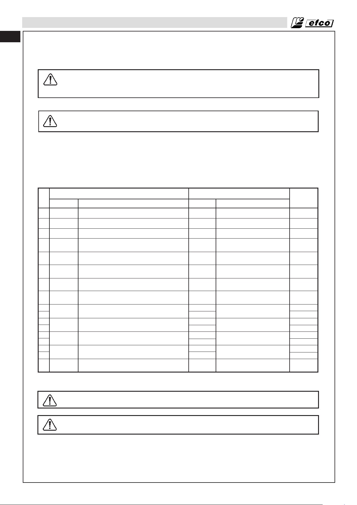
p. n.
4095605
4095597
4175157
63019007B
61172019
4180053
4180052
4180961
4095638R
4095673R
4095674R
4095565R
4095641R
Cutting attachments
Descriptions
Nylon blade with 3 teeth, Ø 10”
Nylon blade with 4 teeth, Ø 10”
“Pro Trim Univesral” Head 3 blades, Ø 12”
“Tap’n go” head with 2 nylon lines Ø 5.1”
with .11” line
“Tap’n go” head with 2 nylon lines Ø 5.1”
with .094” line
Universal multi-line head Ø 2.75”
with 8 lines (0.13”)
Universal multi-line head Ø 2.75”
with 6 lines (11”)
Universal multi-line head Ø 5.2”
with 8 lines (0.11”)
Steel blade with 3 teeth, Ø 10”, thickness .05”
Steel blade with 3 teeth, Ø 10”, thickness .07”
Steel blade with 3 teeth, Ø 12”, thickness .09”
Steel blade with 8 teeth, Ø 9”, thickness .05”
Steel blade with 3 teeth, Ø 10”, thickness .11”
p. n.
61170127
4174273A
4174273A
4174273A
61170127
4174273A
61170127
4174273A
61170127
4174273A
61170127
4174273A
61170127
4174273A
61170127
4174273A
4174273A
Guards
Descriptions
Plastic guard*
Plastic guard*
Plastic guard*
Plastic guard
Plastic guard
Plastic guard
Plastic guard
Plastic guard
Plastic guard*
Plastic guard*
Plastic guard*
Plastic guard*
Plastic guard*
Models
DS 2600 4S
DS 3600 4S
DS 3600 4S
DS 3600 4S
DS 2600 4S
DS 3600 4S
DS 2600 4S
DS 3600 4S
DS 2600 4S
DS 3600 4S
DS 2600 4S
DS 3600 4S
DS 2600 4S
DS 3600 4S
DS 2600 4S
DS 3600 4S
DS 3600 4S
* protection p. n. 4174283A not needed
WARNING: The use of cutting devices not authorized by the manufacturer can generate
safety risks.
WARNING: A saw blade can not be used in connection with a loop handle.
10
Page 11
SAFETY RULES
Safety equipment checking
WARNING: Never use a machine with faulty safety equipment. The machine’s safety
equipment must be checked and maintained as described in this section. If your machine
fails any of these checks contact your service agent to get it repaired.
Throttle lock
The throttle lock is designed to prevent accidental operation of the throttle control. This arrangement means
that the throttle control is automatically locked at the idle setting.
Make sure the throttle control is locked at the idle setting when the throttle lock is released.
Press the throttle lock and make sure it returns to its original position when you release it.
Check that the throttle control and throttle lock move freely and that the return springs work properly.
Stop switch
Use the stop switch to switch off the engine.
Start the engine and make sure the engine stops when you move the stop switch to the stop setting.
Cutting attachment guard
This guard is intended to prevent loose objects from being thrown towards the operator. The guard also
protects the operator from accidental contact with the cutting attachment.
Check that the guard is undamaged and not cracked. Replace the guard if it has been exposed to impact or
is cracked.
Always use the recommended guard for the cutting attachment you are using. See chapter on Technical data.
en
WARNING: Never use a cutting attachment without an approved guard. See the section on
Technical Data. Use of an incorrect or faulty guard may lead to serious personal injury.
Precautions to Reduce Vibration Risk
• The brush cutter is provided with anti-vibration (AV) system; never alter or modify it.
• Wear gloves and keep your hands warm.
• Keep the blade sharp and the brush cutter, including the AV system, well maintained. A dull blade will increase
the vibrations transmitted to your hands.
• When using a string cord attachment check that the cord is correctly wound; an unbalanced attachment
will highly increase the vibration level.
• Maintain a firm grip at all times, but do not squeeze the handles with constant, excessive pressures, take
frequent breaks. All the above mentioned precautions do not guarantee that you will not sustain
whitefinger disease or carpal tunnel syndrome. Therefore, continual and regular users should monitor
closely the condition of their hands and fingers. If any of the above symptoms appear, seek medical advice
immediately.
Maintenance Precaution
WARNING: Never operate a brush cutter that is damaged, improperly adjusted, or is not
completely and securely assembled.
• Be sure that the cutting attachment stops moving when the throttle control trigger is released. If the
cutting attachment moves at idle speed, the carburetor may need adjusting, see Operation-Carburetor
Adjusting Section. If the cutting attachment still moves at idle speed after adjustment has been made,
contact a Servicing Dealer for adjustment and discontinue use until the repair is made.
WARNING: All brush cutter service, other than items in the Operator's Manual maintenance
instructions, must be performed by competent brush cutter service personnel. (If
improper tools are used to remove the flywheel or clutch, or if an improper tool is used to
hold the flywheel in order to remove the clutch, structural damage to the flywheel could
occur which could cause the flywheel to burst and serious injury could result.)
11
Page 12
en
SAFETY RULES
• Never modify your brush cutter in any way.
• Keep the handles dry, clean, and free of oil or fuel.
WARNING: Use only recommended accessories and replacement parts.
• Never touch the cutting attachment or attempt to service the brush cutter while the engine is running.
• Never use fuel for cleaning operations.
• Keep the brush cutter in a dry place, off the ground with the blade guard on and the tanks empty.
• If your brush cutter is no longer usable, dispose of it properly without damaging the environment by
handing it in to your local Dealer who will arrange for its correct disposal.
• Replace immediately any safety device when damaged or broken.
WARNING: The muffler and other parts of the engine (e.g. fins of the cylinder, spark plug)
become hot during operation and remain hot for a while after stopping the engine.
To reduce risk of burns do not touch the muffler and other parts while they are hot.
12
Page 13

ASSEMBLY
Fitting the loop handle
Fit the handle onto the shaft arm and secure it using screws (A,
Fig. 16), washers, and nuts. The handle position is calculated
depending on the requirements of the operator.
Fitting the cutting attachment guard
en
16
18
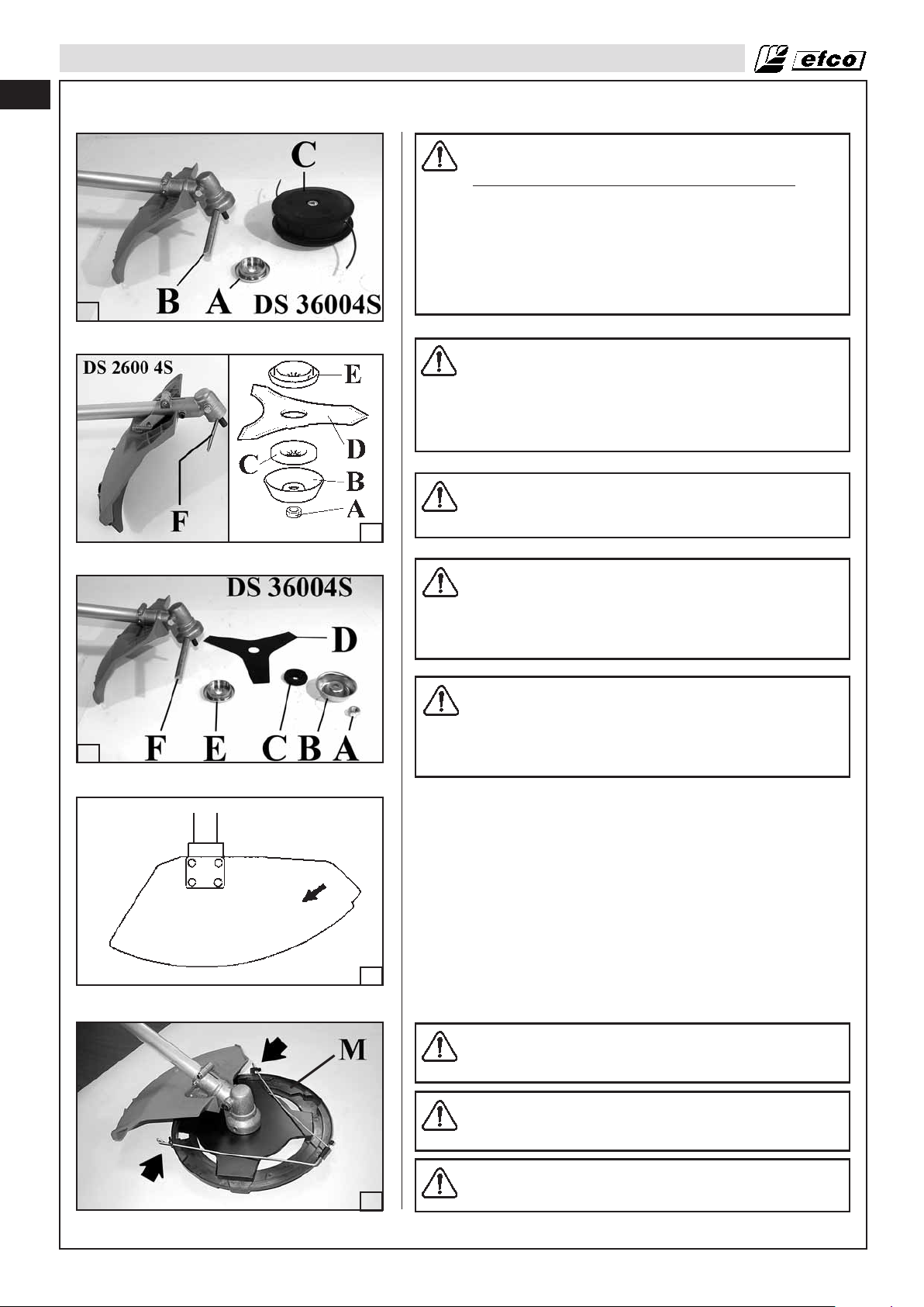
Fitting the safety guard (Fig.18-19)
Fit the blade guard (A) to the shaft arm with screws (B) in a
position allowing the operator to work safely.
NOTE: assemble the trimmer guard (C, Fig.18) when using the
nylon heads. Secure the trimmer guard (C) to the protection
(A) by means of the screw (D).
WARNING: Never use disks for wood.
WARNING: Never use a cutting attachment without
an approved guard. See the section on
Recommended cutting attachments (Page 10)
incorrect or faulty guard may lead to serious
personal injury.
WARNING: The deflector provided with your brush
cutter may not protect the operator from all foreign
objects (gravel, glass, wire, etc) thrown by the
rotating cutting attachment. Thrown objects may also
ricochet and strike the operator.
. An
19
20
WARNING: Immediately replace a broken or damaged
guard; never try to mount the guard in incorrect
position.
Assembling the cutting attachment
WARNING: When fitting the cutting attachment it is
extremely important that the drive flange engages
correctly in the centre hole of the cutting attachment.
If the cutting attachment is fitted incorrectly it can
result in serious and/or fatal personal injury.
13
Page 14
en
21
ASSEMBLY
22
WARNING: Only use cutting attachments with the
guards we recommend! See the chapter on
Recommended cutting attachments (Page 10). Refer
to the instructions for the cutting attachment to
check the correct way to load the cord and the
correct cord diameter. Keep the teeth of the blade
correctly sharpened! Follow our recommendations.
Also refer to the instructions on the blade packaging.
Maintain the correct blade setting! Follow our
instructions.
WARNING: Always stop the engine before doing any
work on the cutting attachment. The attachment
continues to rotate even after the throttle has been
released. Ensure that the cutting attachment has
stopped completely and disconnect the HT lead from
the spark plug before you start to work on it.
WARNING: Using an incorrect cutting attachment or
an incorrectly sharpened blade increases the risk of
kickout.
23
24
WARNING: Always discard a blade that is bent,
twisted, cracked, broken or damaged in any other
way (Fig.19, page 13). Never attempt to straighten a
twisted blade so that it can be reused. Only use
original blades of the specified type.
WARNING: To reduce the risk of serious injury, never
use wire or metal-reinforced line or other material in
place of the nylon cutting lines. Pieces of wire could
break off and be thrown at high speed toward the
operator or bystanders.
Fitting the trimmer head (Fig.20, page 13- Fig. 21)
Put the upper (A) flange in place. Push the head fixing button (B)
and tighten the head (C) counter-clockwise by hand.
Fitting the blade (Fig.22-23)
Loosen the nut (A) for DS 2600 4S or screw (A) for DS 3600 4S
clockwise; remove cup (B) and lower flange (C). fix the blade (D)
onto the upper flange (F) making sure that the rotation direction is
correct. Fix the lower flange (C), the cup (B) and tighten nut (A) for
DS 2600 4S or screw (A) for DS 3600 4S counter-clockwise. Push
the button (F) to block the blade and allow the nut (A) to be tightened to 18.4 ftlb (25 Nm).
14
WARNING: Arrows on the cutting attachment guard
(Fig.24) show the correct direction of rotation of the
cutting tool.
WARNING: Fit the blade protection (M) p.n. 4196086
as shown (Fig.25) before transporting or storing the
brush cutter.
CAUTION: Never use the brush cutter without the cup
(B, Fig.22-23) to avoid damages to the thread.
25
Page 15
OPERATION
26
Fueling (Do Not Smoke!) (Fig. 28)
This product is powered by a 4-cycle engine. Store unleaded
gasoline in a clean container approved for gasoline (Fig. 26).
RECOMMENDED
OPERATE ON UNLEADED GASOLINE INTENDED FOR
AUTOMOTIVE USE WITH AN OCTANE RATING OF 89 ([R + M]
/ 2) OR HIGHER (Fig. 27).
Never use stale or contaminated gasoline or an oil/gasoline mixture. Avoid getting dirt or water in the fuel tank.
en
WARNING: Never touch or adjust the blade while the
motor is running. The blade is very sharp, always
wear protective gloves when performing maintenance.
WARNING: After use the bevel gear may be very hot,
always wear protective gloves when performing
maintenance.
FUEL: THIS ENGINE IS CERTIFIED TO
27
28
NOTE:
Gasoline spoils very quickly depending on factors such as light
exposure, temperature and time. In worst cases, gasoline can be
contaminated within 1 month. Using contaminated gasoline can
seriously damage the engine (carburettor clogged, valves tuck).
Such damage due to spoiled fuel is disallowed from coverage by
the warranty. To avoid this please strictly follow these recommendations:
• Only use specified gasoline.
• To slow deterioration, keep gasoline in a certified fuel container.
• If long storage (more than 1 month) is foreseen, drain fuel tank
and carburetor.
Gasoline Containing Alcohol
If you decide to use a gasoline containing alcohol (gasohol), be
sure it’s octane rating is at least as high as that recommended by
Emak. There are two types of ‘‘gasohol’’: one containing ethanol,
and the other containing methanol. Do not use gasohol that contains more than 10% ethanol. Do not use gasoline containing
methanol (methyl or wood alcohol) that does not also contain
cosolvents and corrosion inhibitors for methanol. Never use gasoline containing more than 5% methanol, even if it has cosolvents
and corrosion inhibitors.
NOTE:
• Fuel system damage or engine performance problems resulting
from the use of fuels that contain alcohol is not covered under
the warranty. Emak cannot endorse the use of fuels containing
methanol since evidence of their suitability is as yet incomplete.
• Before buying fuel from an unfamiliar station, try to find out if
the fuel contains alcohol, if it does, confirm the type and percentage of alcohol used. If you notice any undesirable operating symptoms while using a gasoline that contains alcohol, or
one that you think contains alcohol, switch to a gasoline that
you know does not contain alcohol.
15
Page 16
en
OPERATION
29
30
Filling the Tank
WARNING: Follow safety instruction for fuel
handling. Always shut off engine before fuelling.
Never add fuel to a machine with a running or hot
engine. Move at least 10 feet (3 m) from refuelling
site before starting engine (Fig. 29). DO NOT
SMOKE!
1. Clean surface around fuel cap to prevent contamination.
2. Loosen fuel cap slowly.
3. Carefully pour fuel into the tank. Avoid spillage.
4. Prior to replacing the fuel cap, clean and inspect the gasket.
5. Immediately replace fuel cap and hand tighten. Wipe up any
fuel spillage.
NOTE: It is normal for smoke to be emitted from a new
engine during and after first use.
WARNING: Check for fuel leaks, if any are found,
correct before use. Contact a Servicing Dealer if
necessary.
Engine Oil Tank
Engine oil level
CAUTION: Running the engine with insufficient oil
can cause serious engine damage.
Be sure to check the engine on a level surface with
the engine stopped.
31
32
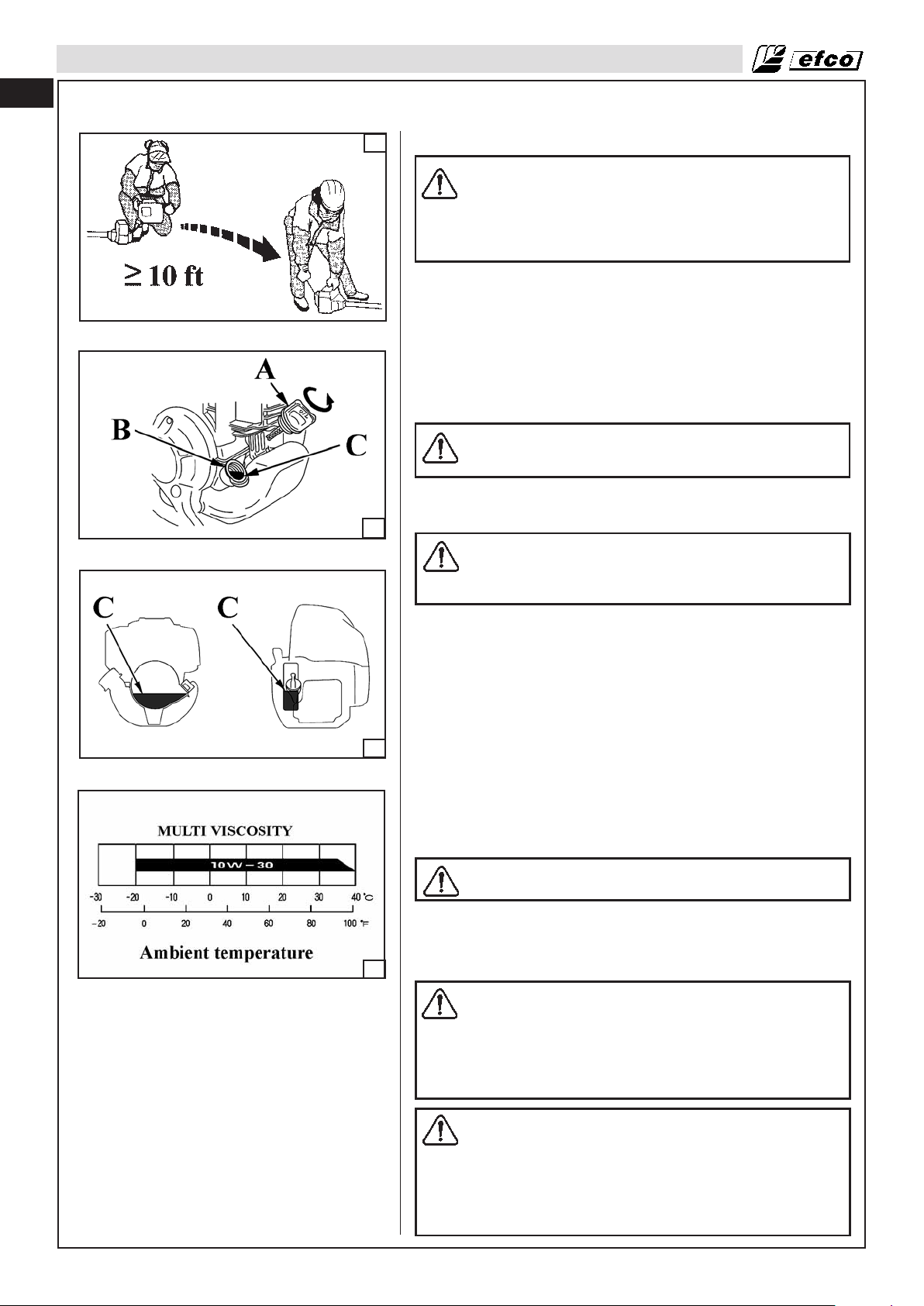
1. Remove the oil filler cap (A, Fig.30) and check the oil level: it
should reach the top of the oil filler neck (B).
2. If the level is low, fill to the top (C, Fig.31) of the oil filler neck
with the recommended oil.
Add the engine oil slowly to avoid overflowing, as the engine oil
tank capacity is small.
Every 10 hours, check the engine oil level and replenish oil up to
the top of the oil filler neck if the engine is operated for more than
10 hours continuously.
Use Efco 4-stroke, or an equivalent high detergent, premium quality motor oil certified to meet or exceed U.S. automobile manufacturer’s requirements for service classifications SG, SF. Motor
oils classified SG, SF will show this designation on the container.
SAE10W-30 (Fig.32) is recommended for general, all temperature use.
CAUTION: Using nondetergent oil or 2-stroke engine
oil could shorten the engine’s service life.
The recommended operating range of this engine is 23 °F to 104
°F (–5 °C to 40 °C).
Preparation for Cutting
WARNING: When using rigid blades, avoid cutting
close to fences, sides of buildings, tree trunks,
stones or other such objects that could cause the
brush cutter to kick out or could cause damage to the
blade. We recommends use of the nylon line heads
for such jobs. In addition, be alert to an increased
possibility of ricochets in such situations.
16
WARNING: The brush cutter is normally to be used at
ground level with the cutting attachment parallel to
the ground. Use of a brush cutter above ground level
or with the cutting attachment perpendicular to the
ground may increase the risk of injury, since the
cutting attachment is more fully exposed and the
brush cutter may be more difficult to control. Never
use your brush cutter as a hedge trimmer.
Page 17
OPERATION
WARNING: If the blade loosens after being properly
tightened, stop work immediately. The retaining nut
may be worn or damaged and should be replaced.
Never use unauthorized parts to secure the blade. If
the blade continues to loosen, see your dealer. Never
use a brush cutter with a loose blade.
Basic Cutting Procedure
en
33
34
35
1. Wear non-slip gloves for maximum grip and protection.
WARNING: Hold the brush cutter firmly with both
hands (Fig. 33). Always keep your body is to the left
of tube. Never use a cross-handed grip. Left-handers
should follow these instructions too.
Keep a proper cutting stance (Fig. 34).
2. Maintain a proper grip (Fig. 33) on the brush cutter whenever
the engine is running. The fingers should encircle the
handlebar and the thumb is wrapped under the handlebar.
Fitting the harness
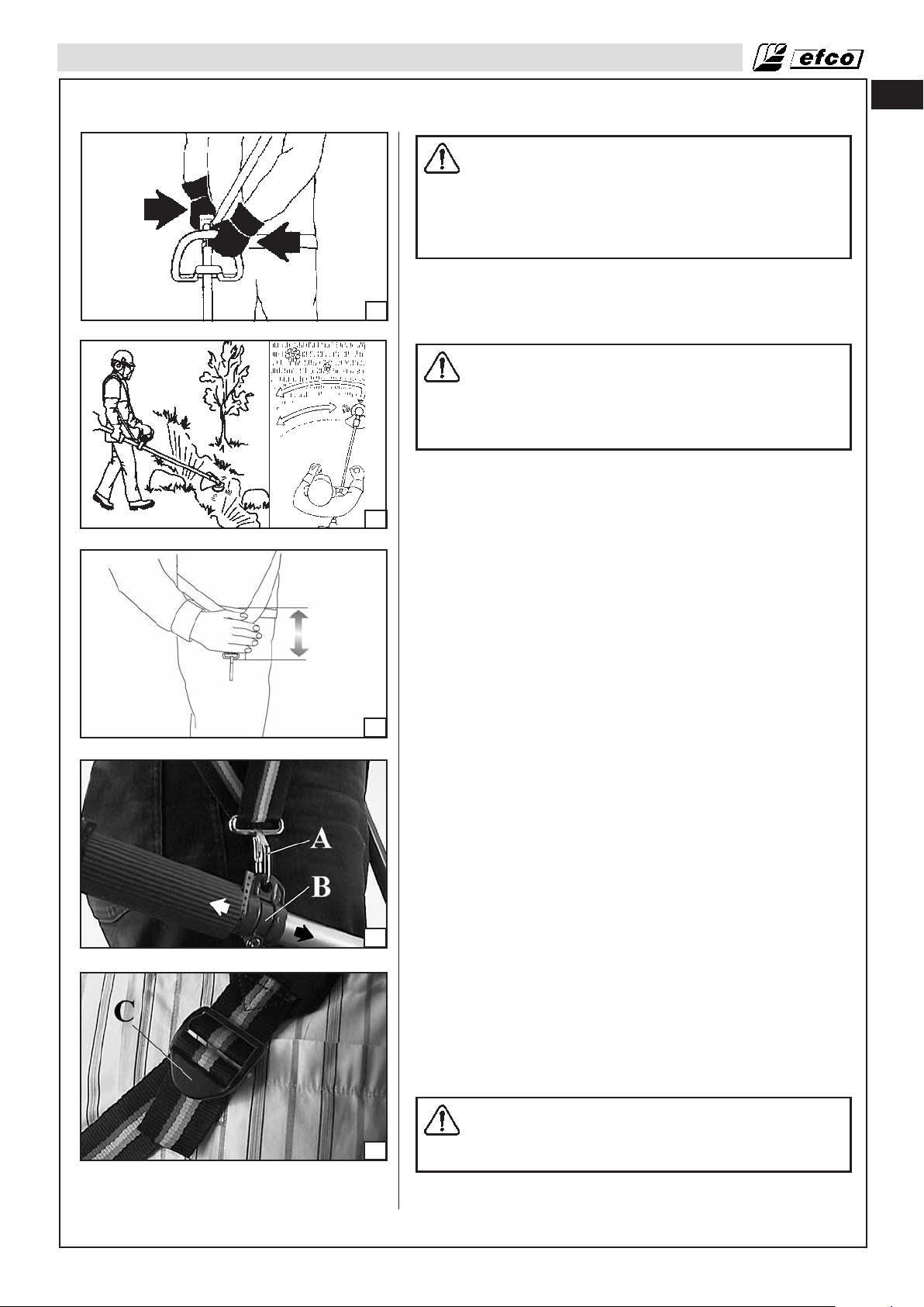
Correct adjustment of the harness permits the brush cutter to be
properly balanced and at an appropriate height from the ground
(Fig.35):
• Put on the single harness.
• Hook the brush cutter to the harness using the hook (A,
Fig.36).
• Position the hook (B, Fig.36) to obtain the best brush cutter
balance.
• Position the buckle (C, Fig.37) to obtain the correct brush cut-
ter height.
36
37
Correct balance (Fig. 36)
1 Forestry clearing
The machine is balanced by moving the support ring on the
machine forwards or backwards. On some models the support
ring is fixed, however, this will then have a number of holes for the
support hook. The machine is correctly balanced when it freely
hangs horizontally from the support hook. In this way the risk of
hitting stones is reduced if you need to release the handlebar.
2 Grass clearing
Let the blade balance at a comfortable cutting height, i.e. close to
the ground.
Work Area Precautions
WARNING: Cut only grass or weed. Cut wood only
with appropriate saw blade. Do not cut metal,
plastics, masonry, or non-wood building materials.
17
Page 18
en
OPERATION
38
• Never allow children to operate your brush cutter. Only allow
others to use this brush cutter who have read this Operator's
Manual or received adequate instructions for the safe and
proper use of this brush cutter.
• Keep everyone - helpers, bystanders, children, and animals at
a safe distance from the cutting area (Fig. 38). During
operations, keep a minimum distance of 50 feet (15 m)
between workers.
• Always cut with both feet on solid ground to prevent being
pulled off balance.
• Make sure you can move and stand safely. Check the area
around you for possible obstacles (roots, rocks, branches,
ditches, etc.) in case you have to move suddenly. Take great
care when working on sloping ground.
• Do not cut above chest height, as a brush cutter held higher is
difficult to control against kickout forces.
• Do not work near electrical wires. Leave this operation for
professionals.
• Cut only when visibility and light are adequate for you to see
clearly.
• Do not cut from a ladder, this is extremely dangerous.
• Stop the brush cutter if the blade strikes a foreign object.
Inspect the brush cutter and repair parts as necessary.
• Keep the blade out of dirt and sand. Even a small amount of dirt
will quickly dull a blade and increase the possibility of kickout.
• Stop the engine before setting the brush cutter down.
• Be particularly cautious and alert while wearing hearing
protection because such equipment may restrict your ability to
hear sounds indicating danger (calls, signals, warnings, etc).
• Be extremely cautious when working on slopes or uneven
ground.
WARNING: Never use rigid blades when cutting in
stony areas. Thrown objects or damaged blades may
result in serious or fatal injury to the operator or
bystanders. Watch out for thrown objects. Always
wear approved eye protection. Never lean over the
cutting attachment guard. Stones, rubbish, etc. can
be thrown up into the eyes causing blindness or
serious injury. Keep unauthorised persons at a
distance. Children, animals, onlookers and helpers
should be kept outside the safety zone of 50 ft (15 m).
Stop the machine immediately if anyone approaches.
Never swing the machine around without first
checking behind you to make sure no-one is within
the safety zone.
WARNING: Never cut when visibility is poor or in
very high or low temperatures or in freezing weather.
Starting The Engine
WARNING: When the engine is started with the choke
in either the choke or start throttle positions the
cutting attachment will start to rotate immediately.
• Place the brush cutter on level ground and ensure that no
objects or obstructions are in immediate vicinity which could
18
Page 19

OPERATION
en
39
40
40
come in contact with the cutting attachment. Hold the body of
the machine on the ground using your left hand (CAUTION!
Not with your foot!), see Fig. 39.
• Slowly push the purge bulb 6 to 8 times (A, Fig. 40).
• Pull the throttle trigger (C, Fig.41) and stop it at half-throttle put
the ON/OFF switch (B) in the position then release the throttle trigger (C).
• Pull the choke lever (D, Fig. 42) in the CLOSE position.
• Pull the starter rope (Fig. 39) until the first firing of the engine
is heard (no more than five (5) pulls). A new unit may
require additional pulls.
• Never wrap the starter cord around your hand.
• When the engine starts, gradually move the choke lever (D,
Fig.43) to the OPEN position.
• Once the engine has started, press throttle trigger (C, Fig.41)
to release it from the half-throttle position and let the engine
idle. Warm up the engine until it run smoothly.
• When pulling the starter rope, do not use the full extent of the
rope as this can cause the rope to break. Do not let starter rope
snap back. Hold the handle and let the rope rewind slowly.
WARNING: Use the half-throttle device only in the
phase of starting the engine to cold.
To start the engine when warm, switch (E) must be positioned as
shown in Fig.44, page 20.
WARNING: Do not cut material with the choke/fast
idle lever at the CLOSE position. Do not operate your
brush cutter with the starting throttle lock engaged.
Cutting with the starting throttle lock engaged does
not permit the operator proper control of the brush
cutter.
41
42
NOTE - STARTING WARM ENGINE:
Follow above starting instructions, but do not use the CLOSE
position for start up again.
WARNING: Weather conditions and altitude may
affect carburetion. Do not allow bystanders close to
the brush cutter while adjusting the carburetor.
Keep the engine at full throttle the entire time you are cutting.
High Altitude Operation
At high altitude, the standard carburettor air-fuel mixture will be
excessively rich. Performance will decrease, and fuel consumption
will increase.
High altitude performance can be improved by specific modifications to the carburetor. If you always operate the engine at altitudes higher than 5,000 feet (1,500 m) above sea level, have your
authorized Efco dealer perform these carburettor modifications.
Even with suitable carburettor jetting, engine horse power will
decrease approximately 3.5% for each 1,000 feet (300 m) increase in altitude. The effect of altitude on the horse power will be
greater than this if no carburettor modification is made.
CAUTION: Operation of the engine at an altitude
lower than the carburettor is jetted for may result in
reduced performance, overheating, and serious engine damage caused by an excessively lean air / fuel
mixture.
43
Breaking-in the Engine
The engine reaches the maximum power after 5-8 hours of activity.
19
Page 20

en
OPERATION
During this period of breaking-in do not make the machine
function idly at full throttle, to avoid excessive functioning stress.
Difficult Starting (or starting a flooded engine)
The engine may be flooded with too much fuel if it has not started
after 10 pulls. Flooded engines can be cleared of excess fuel by
44
45
following the warm engine starting procedure listed above. Ensure
the ON/STOP switch is in the ON position. Starting could require
pulling the starter rope handle many times depending on how
badly the unit is flooded. If engine fails to start refer to the
TROUBLESHOOTING TABLE (page 31).
Engine is Flooded
• Set the on/off switch to STOP.
• Unscrew the screw on the cover (1, Fig. 45).
• Remove the cover (2).
• Engage a suitable tool in the spark plug boot (3, Fig. 46).
• Pry off the spark plug boot.
• Unscrew and dry off the spark plug.
• Open the throttle wide.
• Pull the starter rope several times to clear the combustion
chamber.
• Refit the spark plug and connect the spark plug boot, press it
down firmly – reassemble the other parts.
• Set the on/off switch to I, the starting position.
• Set the choke lever to OPEN position – even if engine is cold.
• Now start the engine.
CAUTION! – During the breaking-in period do not
vary the carburetion to obtain a presumed power
increment; the engine can be damaged.
46
47
Stopping The Engine
Release the throttle trigger (C, Fig. 47) and let the engine return
to idle.
To stop the engine, move the on/off switch (B) to the “ STOP ”
position. Do not put the brush cutter on the ground when the
cutting attachment is still moving.
In the event that the “ STOP ” position of the switch will not
function, pull the choke lever in the CLOSE position (Fig. 42, page
19) to stop the engine.
Pre-operation checking
WARNING: THE CUTTING ATTACHMENT SHOULD
NEVER TURN AT IDLE. Turn the idle speed screw “T”
counter-clockwise to reduce the idle RPM, or contact
a Servicing Dealer for adjustment and discontinue
use until the repair is made.
Serious personal injury may result from the cutting
attachment turning at idle.
A damaged clutch may cause a cutting attachment to rotate at idle
speed and increase the risk of personal injury from loss of control
and from contact with the cutting tool.
20
Page 21
OPERATION
Working Techniques
General working instructions
WARNING: This section describes the basic safety
precautions for working with clearing saws and
trimmers. If you encounter a situation where you are
uncertain how to proceed you should ask an expert.
Contact your dealer or your service workshop. Avoid
all usage which you consider to be beyond your
capability. You must understand the difference
between forestry clearing, grass clearing and grass
trimming before use.
Basic safety rules
1. Look around you:
• To ensure that people, animals or other things cannot affect
your control of the machine.
• To ensure that people, animals, etc., do not come into contact
with the cutting attachment or loose objects that are thrown
out by the cutting attachment.
en
WARNING: Do not use the machine unless you are
able to call for help in the event of an accident.
2. Do not use the machine in bad weather, such as dense fog,
heavy rain, strong wind, intense cold, etc. Working in bad
weather is tiring and often brings added risks, such as icy
ground, unpredictable felling direction, etc.
3. Make sure you can move and stand safely. Check the area
around you for possible obstacles (roots, rocks, branches,
ditches, etc.) in case you have to move suddenly. Take great
care when working on sloping ground.
4. Switch off the engine before moving to another area.
5. Never put the machine down with the engine running.
• Always use the correct equipment.
• Make sure the equipment is well adjusted.
• Follow the safety precautions.
• Organise your work carefully.
• Always use full throttle when starting to cut with the blade.
• Always use sharp blades.
• Avoid stones.
WARNING: Neither the operator of the machine nor
anyone else may attempt to remove the cut material
while the engine is running or the cutting equipment
is rotating, as this can result in serious injury. Stop
the engine and cutting equipment before you remove
material that has wound around the blade shaft as
otherwise there is a risk of injury. The bevel gear can
get hot during use and may remain so for a while
afterwards. You could get burnt if you touch it.
47A
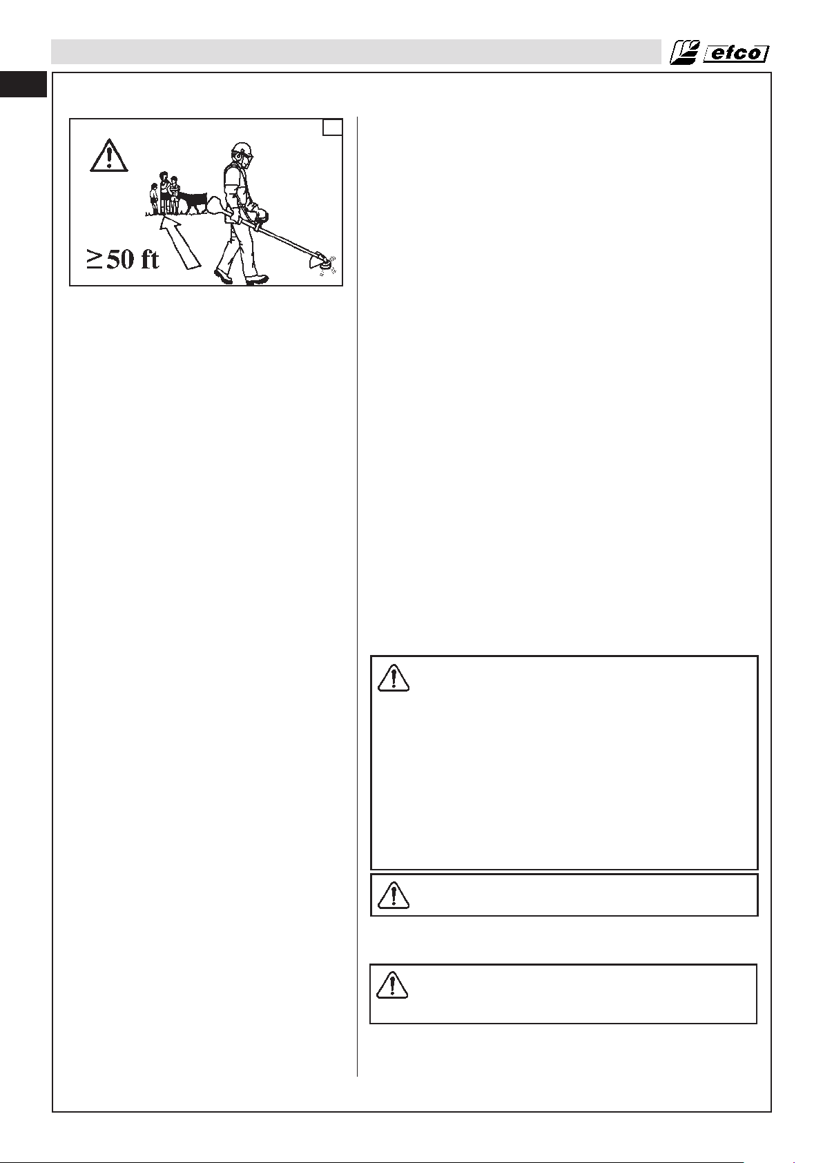
WARNING: Watch out for thrown objects. Always
wear approved eye protection. Never lean over the
cutting attachment guard. Stones, rubbish, etc. can
be thrown up into the eyes causing blindness or
serious injury. Keep unauthorised persons at a
distance. Children, animals, onlookers and helpers
should be kept outside the safety zone of 50 ft (15 m)
(Fig. 47A). Stop the machine immediately if anyone
approaches. Never swing the machine around
without first checking behind you to make sure noone is within the safety zone.
21
Page 22

en
OPERATION
Check before starting
• Check the blade to ensure that no cracks have formed at the
bottom of the teeth or by the centre hole. Discard a blade if
cracks are found (Fig. 48).
48
49
• Check that the support flange is not cracked due to fatigue or
due to being tightened too much. Discard the support flange if
it is cracked (Fig. 49).
• Ensure the locking nut has not lost its captive force. The
tightening torque of the locking nut should be 18.4 ftlb (25 Nm).
(Fig. 49)
• Check that the blade guard is not damaged or cracked. Replace
the blade guard if it is cracked (Fig. 50).
• Check that the trimmer head and trimmer guard are not
damaged or cracked. Replace the trimmer head or trimmer
guard if they have been cracked (Fig. 50).
WARNING: Sometimes branches or grass get caught
between the guard and cutting attachment. Always
stop the engine before cleaning.
WARNING: Never use the machine without a guard or
with a defective guard.
50
WARNING: The complete clutch cover and shaft must
be fitted before the machine is started, otherwise the
clutch can come loose and cause personal injury.
Ensure the cutting attachment cannot come into
contact with any object. Make sure no unauthorised
persons are in the working area, otherwise there is a
risk of serious personal injury. The safety distance is
50 ft (15 metres).
Working methods
WARNING: Avoid cutting with the area of the blade
between the 12 o’clock and 3 o’clock positions.
Because of the speed of rotation of the blade kickout
can occur if you attempt to cut thick stems with this
area of the blade.
Forestry clearing
• Before you start clearing, check the clearing area, the type of
terrain, the slope of the ground, whether there are stones,
hollows etc.
• Start at whichever end of the area is easiest, and clear an open
space from which to work.
• Work systematically to and fro across the area, clearing a width
of around 13-16 ft (4-5 m) on each pass. This exploits the full
reach of the machine in both directions and gives the operator
a convenient and varied working area to work in.
• Clear a strip around 250 ft (75 m) long. Move your fuel can as
work progresses.
• On sloping ground you should work along the slope. It is much
easier to work along a slope than it is to work up and down it.
• You should plan the strip so that you avoid going over ditches
or other obstacles on the ground. You should also orient the
strip to take advantage of wind conditions, so that cleared
stems fall in the cleared area of the stand.
22
Page 23
OPERATION
Grass clearing using a grass blade
• Grass blades and grass cutters must not be used on woody
stems.
• A grass blade is used for all types of tall or coarse grass.
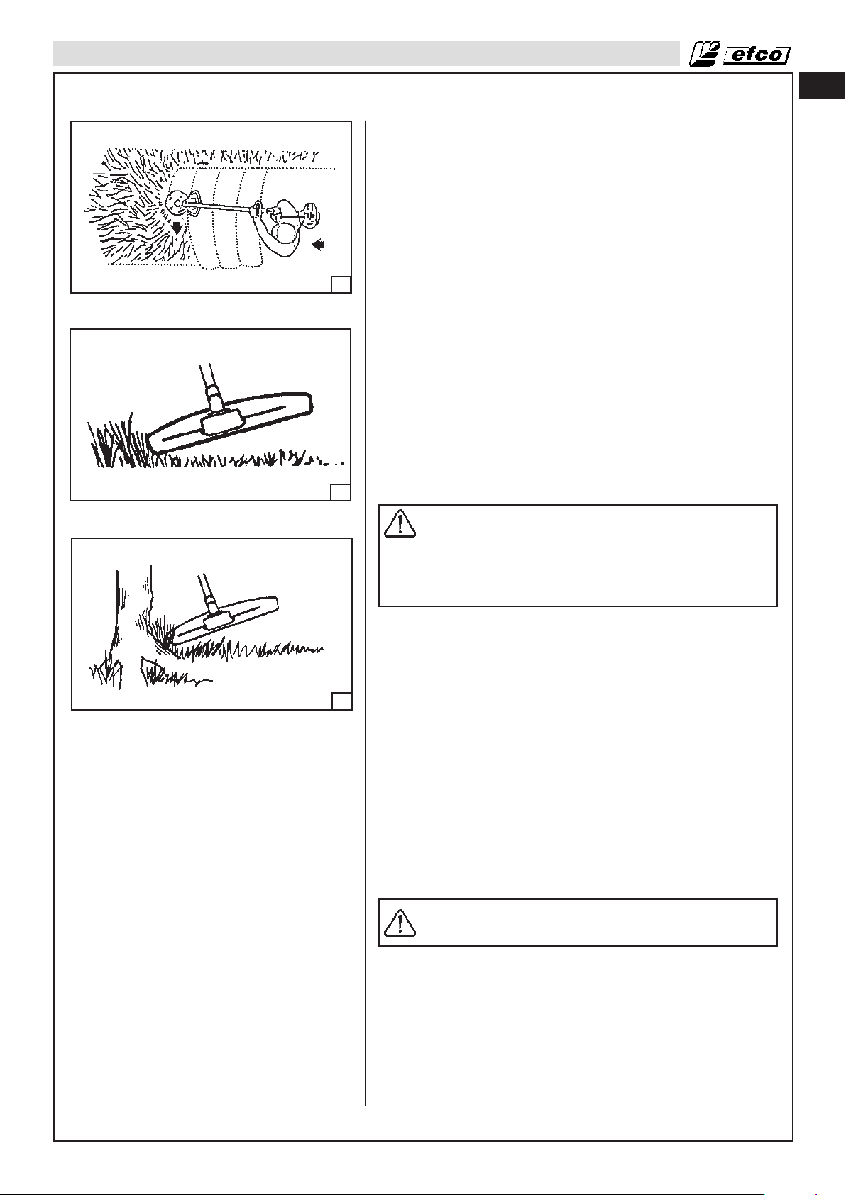
• The grass is cut down with a sideways, swinging movement,
where the movement from right-to-left is the clearing stroke and
the movement from left-to-right is the return stroke. Let the
left-hand side of the blade (between 8 and 12 o’clock) do the
cutting. (Fig. 51)
• If the blade is angled to the left when clearing grass, the grass
51
will collect in a line, which makes it easier to collect, e.g. by
raking.
• Try to work rhythmically. Stand firmly with your feet apart. Move
forward after the return stroke and stand firmly again.
• Let the support cup rest lightly against the ground. It is used to
protect the blade from hitting the ground.
• Reduce the risk of material wrapping around the blade by
following these instructions:
1. Always work at full throttle.
2. Avoid the previously cut material during the return stroke.
• Stop the engine, unclip the harness and place the machine on
the ground before you start to collect the cut material.
en
52
53
Grass trimming with a trimmer head
CAUTION: Do not work with mowing line longer than
the intended diameter. With a properly mounted
guard, the built-in cutter will automatically adjust the
line to its proper length. Overly long lines can
overload the engine, resulting in damage to the
clutch mechanism and nearby parts.
Trimming
• Hold the trimmer head just above the ground at an angle. It is
the end of the cord that does the work. Let the cord work at its
own pace. Never press the cord into the area to be cut. (Fig. 52)
• The cord can easily remove grass and weeds up against walls,
fences, trees and borders, however it can also damage
sensitive bark on trees and bushes, and damage fence posts.
• Reduce the risk of damaging plants by shortening the cord to 4
- 4.7 in. (10-12 cm) and reducing the engine speed.
Clearing
• The clearing technique removes all unwanted vegetation. Keep
the trimmer head just above the ground and tilt it. Let the end
of the cord strike the ground around trees, posts, statues and
the like. (Fig. 53)
CAUTION: This technique increases the wear on the
cord.
• The cord wears quicker and must be fed forward more often
when working against stones, brick, concrete, metal fences,
etc., than when coming into contact with trees and wooden
fences.
• When trimming and clearing you should use less than full
throttle so that the cord lasts longer and to reduce the wear on
the trimmer head.
Cutting
• The trimmer is ideal for cutting grass that is difficult to reach
23
Page 24

en
OPERATION
using a normal lawn mower. Keep the cord parallel to the
ground when cutting. Avoid pressing the trimmer head against
the ground as this can ruin the lawn and damage the tool. (Fig.
54)
• Do not allow the trimmer head to constantly come into contact
with the ground during normal cutting. Constant contact of this
type can cause damage and wear to the trimmer head.
Sweeping
• The fan effect of the rotating cord can be used for quick and
easy clearing up. Hold the cord parallel to and above the area
54
to be swept and move the tool to and fro. (Fig. 55)
• When cutting and sweeping you should use full throttle to
obtain the best results.
WARNING: Never cut when visibility is poor or in
very high or low temperatures or in freezing weather.
WARNING: If the cutting tool or deflector becomes
clogged or stuck, always turn off the engine and
make sure the cutting tool has stopped before
cleaning. Grass, weeds, etc. should be cleaned off
the cutting tool at regular intervals.
55
24
Page 25

MAINTENANCE
Maintenance Chart
Please note that the following maintenance intervals apply for normal operating conditions only. If your daily work
requires longer than normal or harsh cutting conditions are present, then the suggested intervals should be
shortened accordingly.
Complete Machine Inspect (Leaks, Cracks, and Wear) x
Clean after finishing daily work
Controls (Ignition Switch, Choke Lever, Throttle
Trigger, Trigger interlock)
Fuel Tank
Fuel Filter
Cutting Attachments
Bevel Gear
Clutch Drum (2)
Cutting Attachments Guard
Spark Arrestor Screen (in Muffler)
All Accessible Screws and Nuts (Not Adjusting Screws)
Air Filter
Cylinder Fins
Starter System Vents
Starter Rope
Carburetor
Spark Plug
Vibration Mounts
Cutting Attachments nuts and screws
Cutting Attachments nuts and screws
Engine Oil (1)
Valve clearance (2) Check - adjust
Combustion chamber Clean
Fuel tubes Check
Check Operation
Inspect (Leaks, Cracks, and Wear)
Clean
Inspect
Clean, Replace Filter Element (2)
Inspect (Damage, Sharpness, and Wear)
Check Tension
Sharpen
Inspect (Damage and Grease Level)
Inspect (Damage, and Wear)
Replace
Inspect (Damage, and Wear)
Replace
Inspect (Damage, and Wear)
Clean or Replace
Inspect
Retighten
Clean
Replace
Clean
Clean after finishing daily work
Inspect (Damage, and Wear)
Replace
Check Idle (Cutting Attachments must not
rotate at idle)
Check Electrode Gap
Replace
Inspect (Damage, and Wear)
Replace by Dealer
Check that the locking nut of the cutting
equipment is tighten correctly
Check that nuts and screwx are tight
Check level
Change
CheckOil tubes
Faulty
Monthly
Before Each Use
x
x
x
x
x
x
x
x
x
x
x
x
x
Every 2 years (Replace if necessary) (2)
Every 2 years (Replace if necessary) (2)
If Damaged or
x
x
x
x
x
x
x
x
x
After every 300 hrs. (2)
As Required
x
x
x
x
x
x
x
x
x
x
x
x
x
x
x
x
en
1 year or 100 hrs.
6 mouths or 50 hrs.
x
x
x
x
x
x
(1) After first mouth change Engine Oil.
(2) These items should be serviced by your servicing dealer, unless you have the proper tools and are mechanically proficient.
REGULAR SERVICE PERIOD: For commercial use, log hours of operation to determine proper maintenance intervals.
25
Page 26
en
MAINTENANCE
Cutting Attachment Maintenance
WARNING: It is absolutely essential to comply with
the angles and dimensions specified below. If the
blade is incorrectly sharpened there is a risk of
increased kickout of the brush cutter and increase
risk of thrown object, with resulting risk of injury.
Failure to replace or repair damaged cutting
attachment can cause serious injury.
56
General rules
• Only use cutting attachments with the guards we recommend!
• Keep the teeth of the blade correctly sharpened! Follow our
• Keep the correct setting on the saw blade! Follow our
57
• Check the cutting attachment for damage or cracks. A
• Resharpen frequently, take away as little material as possible –
The blades are very sharp, always wear protective
gloves when performing maintenance to the blades.
See Recommended cutting attachments (Page 10).
instructions and use the recommended file gauge. An
incorrectly sharpened or damaged blade increases the risk of
accidents. (Fig. 56)
instructions and use the recommended setting tool. An
incorrectly set saw blade increases the risk of jamming and
kickout, and damage to the saw blade.
damaged cutting attachment should always be replaced. (Fig.
57)
two or three strokes of the file are usually enough.
To avoid out-of-balance:
• Resharpen the cutters uniformly – do not alter the contour of
the parent blade in any way.
• After resharpening about 5 times, have blade checked by your
dealer.
WARNING: Never repair damaged cutting attachments
by welding, straightening or modifying the shape. This
may cause parts of the cutting tool to come off and
result in serious or fatal injuries.
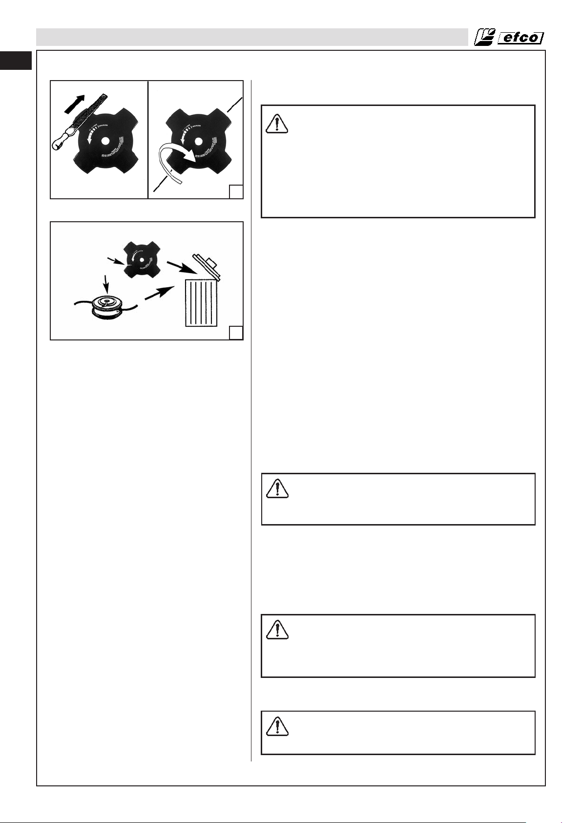
Sharpening grass cutters and grass blades
• See the cutting attachment packaging for correct sharpening
instructions. Sharpen blades and cutters using a single-cut flat
file.
• Sharpen all edges equally to maintain the balance of the blade.
(Fig. 56)
WARNING: Always discard a blade that is bent,
twisted, cracked, broken or damaged in any other
way. Never attempt to straighten a twisted blade so
that it can be reused. Only use original blades of the
specified type.
Trimmer head
26
CAUTION: Always ensure the trimmer cord is wound
tightly and evenly around the drum, otherwise the
machine will generate harmful vibration.
Page 27
MAINTENANCE
• Only use the recommended trimmer heads and trimmer cords.
These have been tested by the manufacturer to suit a
particular engine size. This is especially important when a fully
automatic trimmer head is used. Only use the recommended
cutting attachment. See Recommended cutting attachments
(Page 10).
• Smaller machines generally require small trimmer heads and
vice versa. This is because when clearing using a cord the
engine must throw out the cord radially from the trimmer head
and overcome the resistance of the grass being cleared.
58
59
• The length of the cord is also important. A longer cord requires
greater engine power than a shorter cord of the same
diameter.
• Make sure that the cutter on the trimmer guard is intact. This is
used to cut the cord to the correct length.
• To increase the life of the cord it can be soaked in water for a
couple of days. This will make the line tougher so that it lasts
longer.
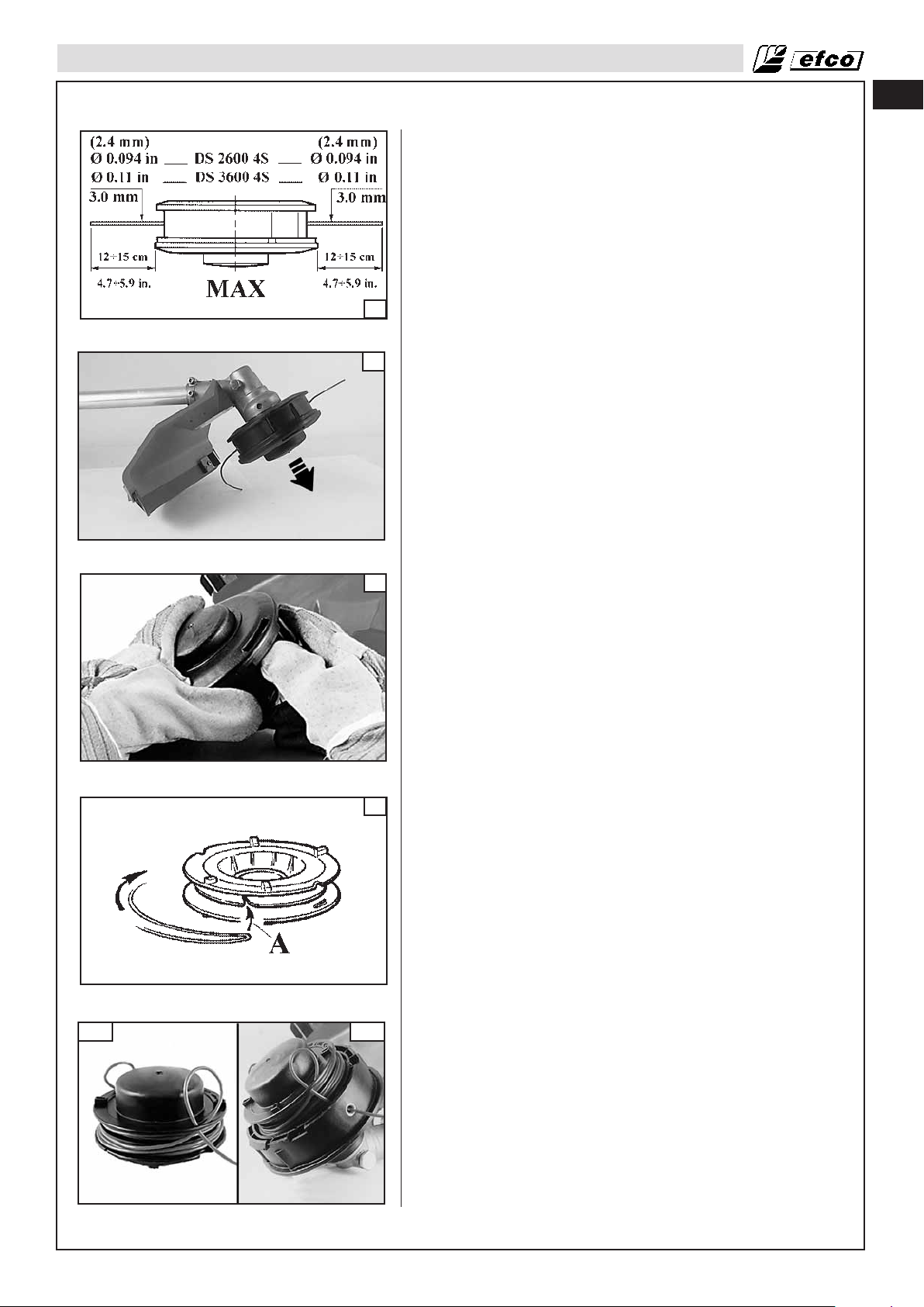
• Only use line of the same diameter as the original to avoid
overloading the engine (Fig.58).
• In order to get more line out of the cutting head, tap it lightly on
the ground while working (Fig.59). NOTE: never hit the nylon
head against hard spots such as concrete or stones, it could be
dangerous.
en
62A
60
61
62B
Replacing the nylon line
1. Press the tab (Fig.60) and remove the cover and the internal
spool.
2. Double back the line, leaving one end 5,5” (14 cm) longer than
the other one. Lock the line in the notch (A, Fig.61). Wind the
line in the direction of the arrow, each end in its chink, regularly,
without crossing them.
3. At the end of the winding, lock in the slits (Fig.62A) Assemble
the spring. Slip the line through the eyelet (Fig.62B) and pull it
towards the outside. Lock the head with the cover.
27
Page 28

en
MAINTENANCE
Carburetor Adjustment
Before adjusting the carburetor, clean the cover vents as shown in
Illustration Fig. 63, and air filter as shown in Illustration Fig. 64,
refer to Operation-Starting Unit and Maintenance-Air Filter
Sections for details. Allow the engine to warm up prior to
carburetor adjustment.
This engine is designed and manufactured in order to comply with
EPA (Environmental Protection Agency) Phase 2 regulations.
The carburetor is factory set and should not require adjusting.
The carburetor will permit only adjustment of the “T” screw (Fig.
63
64
65).
WARNING: Don’t modify the carburetor in any way in
such case the engine will not run in compliance with
emissions regulations.
Idle Speed Adjustment
• If the engine starts, runs, and accelerates but will not idle; turn
the idle speed screw “T” clockwise to increase idle speed (Fig.
65).
• If the cutting attachment turns at idle, turn the idle speed screw
“T” counter-clockwise to reduce the idle RPM and stop the
cutting attachment movement. If the cutting attachment still
moves at idle speed, contact a Servicing Dealer for adjustment
and discontinue use until the repair is made.
65
66
Fuel Filter
Check the fuel filter (Fig. 66) periodically. Replace it if
contaminated or damaged.
Air Filter
WARNING: Do not clean filter in gasoline or other
flammable solvent to avoid creating a fire hazard or
producing harmful evaporative emissions.
If a power drop is noticed, check the air filter.
Move the choke lever (A, Fig.67) to the CLOSE (upwards) position.
Remove the air filter cover (B) by unhooking the upper tab (C) on
the top of the air filter cover and its two lower tabs (D).
Check the air filter (E) each day, change the filter if it not clean or
damaged. Wash the element in a nonflammable or high flash point
solvent and dry it thoroughly. Soak the filter in clean engine oil and
squeeze out the excess oil. Reinstall the air filter. Reinstall the air
filter cover (B) by inserting the lower tabs (D), then insert the
upper tab (C).
A used air filter can never be completely cleaned. It is advisable to
replace your air filter with a new one after 1 year or 100 hrs. of
operation.
Make sure the cover and the support are clean before fitting the
new filter.
28
67
CAUTION: Never run the engine without the air filter,
serious damage could result.
Make sure the air filter is correctly placed in the air
filter cover before reassembly.
Always replace damaged filters.
Do not clean a filter with a brush.
Starter Unit
WARNING: The coil spring is under tension and
could fly apart causing serious injuries. Never try to
disassemble or modify it.
Page 29
MAINTENANCE
Engine
Clean the cylinder fins with compressed air or a brush
periodically (Fig. 68). Dangerous overheating of engine may occur
due to impurities on the cylinder.
WARNING: Never run the machine without all the
parts, including the starting housing, securely in
place.
Because parts can fracture and pose a danger of
thrown objects, leave repairs to the flywheel and
68
clutch to trained Servicing Dealers.
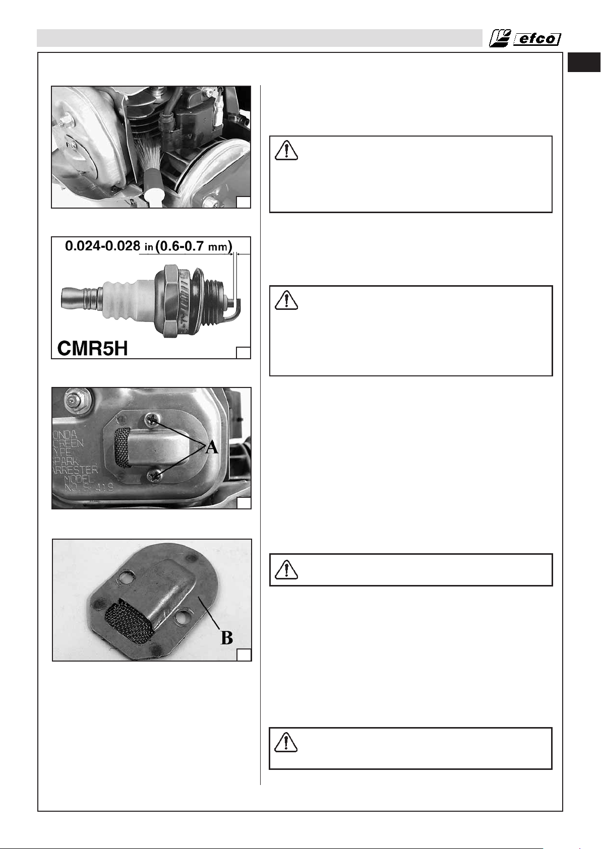
Spark Plug
This engine uses a NGK CMR5H with 0.024-0.028 in (0.6-0.7 mm)
electrode gap (Fig. 69). Use an exact replacement and replace
every six months or more frequently, if necessary.
WARNING: Never test the ignition system with
ignition wire connector removed from spark plug or
with unseated spark plug, since uncontained
sparking may cause a fire. A loose connection
between spark plug terminal and ignition wire
69
connector in the boot may create arcing that could
ignite combustible fumes and cause a fire.
en
70
71
Use only resistor type spark plugs of the approved range.
Factors such as:
- dirty air filter;
- unfavourable running conditions, e.g. operating at part load;
may result in rapid deterioration of the spark plug.
Spark Arresting Muffler
The brush cutter is provided with a Spark Arrester System p.n. S419 (DS 2600 4S) - S-421 (DS 3600 4S) (Fig. 70) complying with
the requirements of SAE J335 standard; you can check the p.n. of
the Spark Arrester System on the muffler itself.
WARNING: A faulty or altered spark arrester system
screen can create a fire hazard.
Through normal use the screen can become dirty and should be
inspected weekly and cleaned as required.
To clean:
• Allow the muffler to cool.
• Remove the two (2) deflector screws (A).
• Remove the deflector and spark arrester (B, Fig. 71).
• Clean and inspect the spark arrester screen. If the spark
arrester screen is damaged, faulty or deteriorated, replace the
screen.
• Reassemble components in reversed order of removal and
torque the screw to 45 in/lbs (4.9 Nm).
WARNING: If the spark arrester screen is damaged,
faulty or deteriorated, replace the screen or entire
muffler assembly.
29
Page 30

en
MAINTENANCE
72
73
The Spark Arrester System needs a periodic and accurate
maintenance and cleaning, in particular:
- check periodically the spark arrester screen and substitute it
when holes, bends or deformations appear;
- check carefully if dust, debris or organic material is in contact
with parts of the Spark Arrester System; clean it often with tools
or shop air.
If the screen needs to be replaced, please order the whole inner part
p.n. H18350Z0H800 (B, Fig. 71, Page 29).
WARNING: Do not operate your brush cutter if the
muffler is damaged, missing or modified. An
improperly maintained muffler will increase the risk
of fire and hearing loss.
Bevel Gear (Fig. 72 - DS 2600 4S) (Fig. 73 - DS 3600 4S)
Fill with grease using the correct tube to the level of the lower lip
of the access hole (A). Do not use more than 0.02 lb (10 grams).
CAUTION: do not use a grease gun. The high
pressure can damage the bearings and seals.
74
75
Use high quality molybdenum bisulphide grease.
Guard
WARNING: If the cutting tool or deflector becomes
clogged or stuck, always turn off the engine and
make sure the cutting tool has stopped before
cleaning. Grass, weeds, etc. should be cleaned off
the cutting tool at regular intervals.
Replace guard if damaged.
Oil Change
Drain the oil while the engine is still warm to assure rapid and
complete draining.
1. Check the fuel filler cap (A, Fig.74) is tightened.
2. Remove the oil filler cap and drain the oil into the oil container
by inclining the engine toward the oil filler neck (B).
3. Refill with the recommended oil (see page 16) and check the
oil level (C, Fig.75).
4. Install the oil filler cap.
If any oil is spilled, make sure to wipe it.
Wash your hands with soap and water after handling used oil.
NOTE: Please dispose of used motor oil in a manner that is compatible with the environment. We suggest you take it in a sealed
container to your local service station for reclamation. Do not
throw it in the trash, pour it on the ground, or down a drain.
30
Page 31

TROUBLESHOOTING
Using Troubleshooting Chart
WARNING: Always stop unit and disconnect spark plug before performing all of the recommended
remedies below except remedies that require operation of the unit.
When you have checked all the possible causes listed and you are still experiencing the problem, see your
Servicing Dealer. If you are experiencing a problem that is not listed in this chart, see your Servicing Dealer for
service.
PROBLEM POSSIBLE CAUSE SOLUTION
en
Engine will not start or will
run only a few seconds after
starting.
(Make sure Ignition switch
is in start position “I”)
Engine starts but will not
accelerate properly:
Engine starts but will not run
properly at high speed.
Engine does not reach full
speed.
Engine overheats
Engine starts, runs, and
accelerates but will not idle.
Cutting attachment running
incorrectly and with high
vibration
Engine starts and runs, but
cutting attachment is not
rotating
WARNING: Never
touch the blade while
the engine is running.
1. No spark
2. Flooded engine.
1. Impurities in fuel tank or water in fuel
tank and in fuel.
2. Air filter dirty.
3. Spark arrester screen dirty.
4. Carburetor requires checking.
1. Spark plug gap incorrect.
2. Dirty air filter.
3. Engine cooling fins clogged
4. Oil level too low
5. Starter pulley fouled by grass cuttings,
etc.
Carburetor requires adjustment.
1. Cutting attachment damaged.
2.Cutting attachment incorrectly
assembled.
1. Cutting attachment incorrectly assembled.
2. Bevel gear damaged.
3. Clutch drum damaged.
1. Check Spark. Remove cover. Check if spark
plug cap is incorrectly attached or
disconnected. Remove spark plug from
cylinder. Check for faulty spark plug or incorrect
gap. (CMR5H).
2. With the ignition switch off, remove spark plug.
Move choke lever to Run position and pull
starter cord 15 to 20 times. This will clear
excess fuel from engine. Clean and reinstall
spark plug. Pull starter three times with choke
lever at run. If engine does not start, move
choke lever to choke and repeat normal starting
procedure. If engine still fails to start, repeat
procedure with a new spark plug.
* Contact a Servicing Dealer for carburetor
adjustment.
* Contact a Servicing Dealer for carburetor
adjustment.
1. Clean fuel tank.
2. Clean per instructions in Maintenance-Air Filter
Section.
3. Clean per instructions in Maintenance-Spark
Arresting Muffler Section.
4. * Contact a Servicing Dealer for carburetor
checking.
1. Adjust plug gap or replace spark plug.
2. Clean air filter.
3. Clean engine cooling fins.
4. Add oil up to correct level.
5. Clean starter assy.
Turn idle speed screw “T” clockwise to increase
idle speed. (If cutting attachment turns at idle,
turn idle speed screw “T” counterclockwise to
decrease speed); see Operation-Carburetor
Adjustment.
1. Replace the cutting attachment.
2. Reassemble the cutting attachment with care.
1. Refer to Assembly-Assembling the cutting
attachment Section.
2. Replace if necessary - contact a Servicing
Dealer.
3. Replace if necessary - contact a Servicing
Dealer.
*Note: This engine complies with EPA (Environmental Protection Agency) regulations which require exhaust emission
control. If your unit exhibits specific performance problems that can not be corrected by the Trouble Shooting Section,
the unit should be taken to a Servicing Dealer for repair.
31
Page 32
DS 2600 4S
ENGINE:
Displacement: 1.5 cu. in (25 cc)
Bore: 1.4 in (35 mm)
Stroke: 1.0 in (26 mm)
PERFORMANCE:
Idle Speed: 3,100 ± 200 RPM
WOT (With Blade): 11,200 RPM
Power: 1.0 HP/0.72 kW (7,000 RPM)
FUEL AND OIL SYSTEMS:
Fuel Tank Capacity: 18.6 oz. (550 ml)
Oil Tank Capacity: 2.7 oz. (80 ml)
Fuel: Unleaded gasoline
DS 2600 4S and DS 3600 4S
IGNITION SYSTEM:
Spark Plug: NGK CMR5H
Spark Plug Gap: 0.024-0.028 in. (0.6-0.7 mm)
STORAGE
TECHNICAL DATA
WARNING: Stop engine and allow to cool, and secure the unit before storing or transporting in
a vehicle. Store unit and fuel in an area where fuel vapors cannot reach sparks or open flames
from water heaters, electric motors or switches, furnaces, etc. Store unit with all guards in place.
Position so that any sharp object cannot accidentally cause injury to passersby. Store the unit
out of reach of children and other unauthorized persons.
1. Drain and clean the fuel tank in a well ventilated area.
2. Drain all fuel from tank into a container approved for gasoline. Run engine until it stops. This will remove all
gasoline which could become stale and leave varnish and gum in the fuel system.
3. Clean all foreign material from the brush cutter. Keep away from corrosive agents such as garden chemicals
and de-icing salts.
4. Abide by all Federal and local regulations for the safe storage and handling of gasoline. Excess fuel should
be used in other 4-cycle engine powered equipment.
CAUTION: It is important to prevent gum deposits from forming in essential fuel system parts
such as the carburetor, fuel filter, fuel hose, or fuel tank during storage. Alcohol blended fuels
(called gasohol or E10 or using ethanol, methanol) can attract moisture which leads to fuel
mixture separation and formation of acids during storage. Acidic gas can damage the engine.
DS 3600 4S
ENGINE:
Displacement: 2.18 cu. in (35.8 cc)
Bore: 1.5 in (39 mm)
Stroke: 1.2 in (30 mm)
PERFORMANCE:
Idle Speed: 3,100 ± 200 RPM
WOT (With Blade): 10,000 RPM
Power: 1.35 HP/1.0 kW (7,000 RPM)
FUEL AND OIL SYSTEMS:
Fuel Tank Capacity: 22 oz. (650 ml)
Oil Tank Capacity: 3.4 oz. (100 ml)
Fuel: Unleaded gasoline
32
en
Page 33
INTRODUCTION
Pour un emploi correct de la débroussailleuse et pour éviter tout accident, ne
commencez pas le travail sans avoir préalablement lu ce manuel avec attention. Vous
trouverez les descriptions du fonctionnement des différents composants, ainsi que les
instructions relatives aux contrôles et aux procédures d'entretien requis.
Remarque : les illustrations et instructions présentes dans ce manuel peuvent
varier en fonction des normes de chaque pays et sont sujettes à modifications
sans préavis par le fabricant.
MANUEL D'UTILISATION
Le manuel d'utilisation est destiné à votre propre protection. LISEZ-LE. Conservez-le
dans un endroit approprié de façon à pouvoir s'y référer au besoin. Ayez pris
connaissance des procédures avant de commencer le montage de l'unité. Une préparation et un entretien corrects vont de paire avec de bonnes performances de la machi-
fr
ne et avec une sécurité optimale.
Contactez votre concessionnaire ou votre distributeur local si vous ne comprenez pas
certaines des instructions délivrées par le présent manuel.
Outre les instructions relatives au fonctionnement, le présent manuel contient des
paragraphes requérant une attention particulière de votre part.
Ces paragraphes sont signalés par les symboles décrits ci-dessous :
Avertissement: présent en cas de risque d'accident, de blessure corporelle ou de
dégâts matériels.
Mise en garde: présent en cas de risque d'endommagement de la machine ou de ses
composants.
AVERTISSEMENT: Afin de garantir un fonctionnement correct et en toute
sécurité de la débroussailleuse, il est recommandé de toujours conserver
le manuel d'utilisation à proximité de la machine. Ne prêtez ou ne louez
jamais votre débroussailleuse sans fournir le présent manuel d'utilisation
et d'entretien.
AVERTISSEMENT: Seules les personnes ayant intégralement compris le
présent manuel sont habilitées à utiliser votre débroussailleuse.
33
Page 34

fr
SOMMAIRE
IDENTIFICATION DU PRODUIT
Composants de la débroussailleuse . . . . . . . . . . . . . . . . . . . . . . . . . . . . . . . . . . . . . . . . . . . . . . 35
SÉCURITÉ
Comprendre les symboles de sécurité . . . . . . . . . . . . . . . . . . . . . . . . . . . . . . . . . . . . . . . . . . . . . 36
Réglementations nationales et locales . . . . . . . . . . . . . . . . . . . . . . . . . . . . . . . . . . . . . . . . . . . . . 36
RÈGLES DE SÉCURITÉ
Précautions de base . . . . . . . . . . . . . . . . . . . . . . . . . . . . . . . . . . . . . . . . . . . . . . . . . . . . . . . . . . . 38
Manipulation du carburant . . . . . . . . . . . . . . . . . . . . . . . . . . . . . . . . . . . . . . . . . . . . . . . . . . . . . . 39
Fonctionnement et sécurité . . . . . . . . . . . . . . . . . . . . . . . . . . . . . . . . . . . . . . . . . . . . . . . . . . . . . 39
Mesures de précaution contre l'effet de rebond . . . . . . . . . . . . . . . . . . . . . . . . . . . . . . . . . . . . . . 40
Comment garder le contrôle . . . . . . . . . . . . . . . . . . . . . . . . . . . . . . . . . . . . . . . . . . . . . . . . . . . . . 40
Fonctions de sécurité . . . . . . . . . . . . . . . . . . . . . . . . . . . . . . . . . . . . . . . . . . . . . . . . . . . . . . . . . . 41
Outils de coupe recommandés . . . . . . . . . . . . . . . . . . . . . . . . . . . . . . . . . . . . . . . . . . . . . . . . . . .41
Vérification des dispositifs de sécurité . . . . . . . . . . . . . . . . . . . . . . . . . . . . . . . . . . . . . . . . . . . . . 42
Mesures de précaution pour réduire le risque de vibrations . . . . . . . . . . . . . . . . . . . . . . . . . . . . 42
Précautions d'entretien . . . . . . . . . . . . . . . . . . . . . . . . . . . . . . . . . . . . . . . . . . . . . . . . . . . . . . . . . 42
ASSEMBLAGE
Montage du poignée simple . . . . . . . . . . . . . . . . . . . . . . . . . . . . . . . . . . . . . . . . . . . . . . . . . . . . . 44
Montage de la protection de l'outil de coupe . . . . . . . . . . . . . . . . . . . . . . . . . . . . . . . . . . . . . . . . 44
Montage de l'outil de coupe . . . . . . . . . . . . . . . . . . . . . . . . . . . . . . . . . . . . . . . . . . . . . . . . . . . . . 44
FONCTIONNEMENT
Alimentation en carburant . . . . . . . . . . . . . . . . . . . . . . . . . . . . . . . . . . . . . . . . . . . . . . . . . . . . . . . 46
Réservoir d’huile moteur . . . . . . . . . . . . . . . . . . . . . . . . . . . . . . . . . . . . . . . . . . . . . . . . . . . . . . . . 47
Préparation à la coupe . . . . . . . . . . . . . . . . . . . . . . . . . . . . . . . . . . . . . . . . . . . . . . . . . . . . . . . . . 47
Démarrage du moteur . . . . . . . . . . . . . . . . . . . . . . . . . . . . . . . . . . . . . . . . . . . . . . . . . . . . . . . . . 49
Utilisation à haute altitude . . . . . . . . . . . . . . . . . . . . . . . . . . . . . . . . . . . . . . . . . . . . . . . . . . . . . . 50
Rodage du moteur . . . . . . . . . . . . . . . . . . . . . . . . . . . . . . . . . . . . . . . . . . . . . . . . . . . . . . . . . . . . 50
Arrêt du moteur . . . . . . . . . . . . . . . . . . . . . . . . . . . . . . . . . . . . . . . . . . . . . . . . . . . . . . . . . . . . . . . 51
Techniques de travail . . . . . . . . . . . . . . . . . . . . . . . . . . . . . . . . . . . . . . . . . . . . . . . . . . . . . . . . . . 51
ENTRETIEN
Tableau d'entretien . . . . . . . . . . . . . . . . . . . . . . . . . . . . . . . . . . . . . . . . . . . . . . . . . . . . . . . . . . . . 51
Entretien de l’outil de coupe . . . . . . . . . . . . . . . . . . . . . . . . . . . . . . . . . . . . . . . . . . . . . . . . . . . . . 57
Réglage du carburateur . . . . . . . . . . . . . . . . . . . . . . . . . . . . . . . . . . . . . . . . . . . . . . . . . . . . . . . . 59
Filtre à carburant . . . . . . . . . . . . . . . . . . . . . . . . . . . . . . . . . . . . . . . . . . . . . . . . . . . . . . . . . . . . . 59
Filtre à air . . . . . . . . . . . . . . . . . . . . . . . . . . . . . . . . . . . . . . . . . . . . . . . . . . . . . . . . . . . . . . . . . . . 59
Démarreur . . . . . . . . . . . . . . . . . . . . . . . . . . . . . . . . . . . . . . . . . . . . . . . . . . . . . . . . . . . . . . . . . . . 59
Moteur . . . . . . . . . . . . . . . . . . . . . . . . . . . . . . . . . . . . . . . . . . . . . . . . . . . . . . . . . . . . . . . . . . . . . . 60
Bougie . . . . . . . . . . . . . . . . . . . . . . . . . . . . . . . . . . . . . . . . . . . . . . . . . . . . . . . . . . . . . . . . . . . . . . 60
Silencieux pare-étincelles . . . . . . . . . . . . . . . . . . . . . . . . . . . . . . . . . . . . . . . . . . . . . . . . . . . . . . . 60
Pignon conique . . . . . . . . . . . . . . . . . . . . . . . . . . . . . . . . . . . . . . . . . . . . . . . . . . . . . . . . . . . . . . . 61
Protection . . . . . . . . . . . . . . . . . . . . . . . . . . . . . . . . . . . . . . . . . . . . . . . . . . . . . . . . . . . . . . . . . . . 61
Renouvellement de l’huile . . . . . . . . . . . . . . . . . . . . . . . . . . . . . . . . . . . . . . . . . . . . . . . . . . . . . . 61
34
DIAGNOSTIC DES PANNES
Utilisation du tableau de diagnostic des pannes . . . . . . . . . . . . . . . . . . . . . . . . . . . . . . . . . . . . . 62
REMISAGE
Remisage de la débroussailleuse . . . . . . . . . . . . . . . . . . . . . . . . . . . . . . . . . . . . . . . . . . . . . . . . 63
CARACTÉRISTIQUES TECHNIQUES
DS 2600 4S . . . . . . . . . . . . . . . . . . . . . . . . . . . . . . . . . . . . . . . . . . . . . . . . . . . . . . . . . . . . . . . . . 63
DS 3600 4S . . . . . . . . . . . . . . . . . . . . . . . . . . . . . . . . . . . . . . . . . . . . . . . . . . . . . . . . . . . . . . . . . 63
Page 35
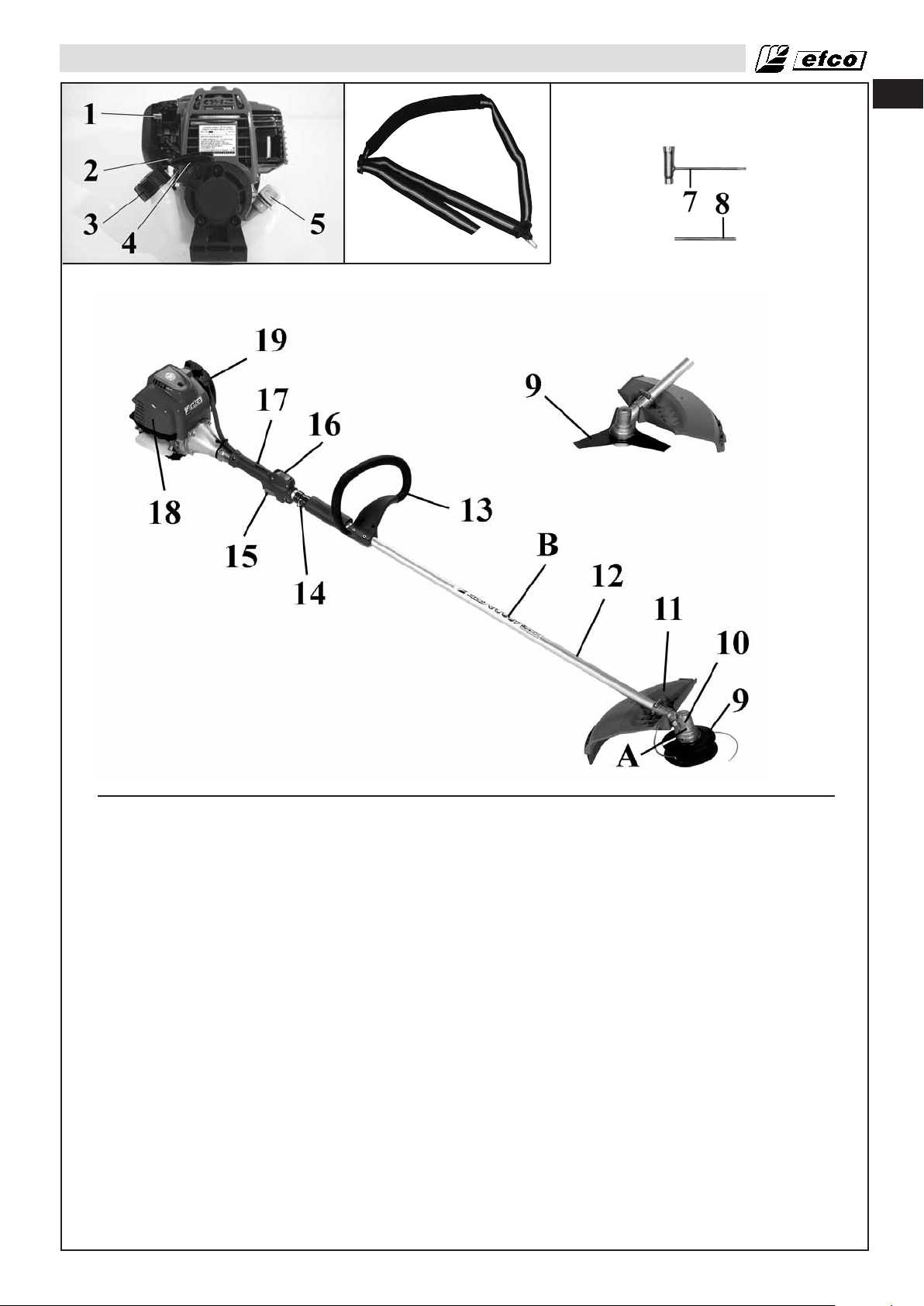
IDENTIFICATION DU PRODUIT
6
fr
Composants de la débroussailleuse
1 - Levier de l'étrangleur
2 - Poire d'amorçage
3 - Bouchon du réservoir de
carburant
4 - Poignée de lanceur
5 - Bouchon réservoir huile
6 - Harnais
7 - Clé mixte
8 - Goujon de fixation
9 - Tête porte-lame / Tête de coupe à fils
10 - Pignon conique
11 - Protection de l'outil de coupe
12 - Tube
13 - Poignée simple
14 - Point d’accrochage du harnais
15 - Gâchette des gaz
16 - Interrupteur Marche/Arrêt
17 - Gâchette de verrouillage des gaz
18 - Couvercle de filtre à air
19 - Protège-silencieux
A - Avertissement de sécurité:
Vitesse de rotation
B - Avertissement de sécurité:
Consignes générales
C - Plaque d’identification
35
Page 36

fr
SÉCURITÉ
Comprendre les symboles de sécurité
- Ce symbole signale un
Avertissement et une Mise en
garde.
- Votre manuel contient des
messages spéciaux attirant votre
attention sur les problèmes liés à
la sécurité, les dégâts éventuels
de la machine, ainsi que des
informations utiles sur le
fonctionnement et l'entretien.
VEUILLEZ LIRE TOUTES CES
INFORMATIONS AVEC
ATTENTION AFIN D'ÉVITER DE
VOUS BLESSER OU
D'ENDOMMAGER LA
MACHINE.
- Portez des lunettes de sécurité,
des protège-tympans, ainsi qu'un
masque de protection lorsque
vous utilisez cette machine.
- Portez des gants de protection
renforcés et antidérapants pour
la manipulation de la
débroussailleuseet des lames.
- Régime maxi. recommandé de
l’axe sortant, tr/min
- Portez des chaussures ou des
bottes de sécurité équipées de
semelles antidérapantes et
coquées.
- Risque de projection.
- Maintenir la distance de sécurité de
15 m (50 ft).
- L’utilisation de la débroussailleuse
avec le disque en bois est interdite
Réglementations nationales et locales
Votre débroussailleuse est équipée d'un silencieux d'échappement à limiteur de température et d'un
pare-étincelles conformément à la directive de pratique recommandée SAE J335 et aux Codes californiens
4442 et 4443. La réglementation régissant tous les terrains forestiers et territoires gérés par les
états de Californie, Maine, Washington, Idaho, Minnesota, New Jersey et Oregon exige l'utilisation
de moteurs à combustion interne équipés de pare-étincelles. Les autres états et agences fédérales
mettent en oeuvre des réglementations identiques.
Si vous utilisez une débroussailleusedans un état ou une région soumise à cette réglementation, vous êtes
légalement responsable du maintien en état de fonctionnement de ces pièces. Le non-respect de cette
réglementation constitue une violation de la loi. L'entretien du pare-étincelles est décrit dans la
section Entretien-Silencieux à pare-étincelles du présent manuel.
Remarque : pour ce qui concerne l'utilisation de débroussailleuses dans le cadre d'une
exploitation forestière, reportez-vous au Code de réglementation fédérale, Articles 1910 et 1928.
AVERTISSEMENT: Le système d'allumage de votre machine génère un champ
électromagnétique de très faible intensité. Il est possible de ce champ crée des
interférences sur le fonctionnement d'un stimulateur cardiaque. Afin de réduire le risque de
blessures graves, voire de mort, les personnes équipées d'un stimulateur cardiaque sont
vivement invitées à consulter leur médecin ainsi que le fabricant du stimulateur avant
d'utiliser la machine.
AVERTISSEMENT: Les surfaces du silencieux deviennent très chaudes en cours de
fonctionnement et après arrêt de la débroussailleuse ; tenez-vous à distance du silencieux.
Tout contact avec le silencieux peut entraîner de graves brûlures.
36
Page 37
SÉCURITÉ
AVERTISSEMENT : L'exposition aux vibrations générées lors de l'utilisation d'outils à
moteurs thermiques peut entraîner des lésions vasculaires ou nerveuses au niveau des
doigts, des mains et des poignets chez les personnes sujettes à des troubles de la
circulation ou à des phénomènes de tuméfactions anormaux. En outre, il a été démontré
que l'utilisation prolongée par temps froid entraînait des lésions des vaisseaux sanguins
chez les personnes saines. En cas d'apparitions de symptômes tels que des
engourdissements douleurs, pertes de force, changements de la couleur ou de la texture
de la peau ou pertes de sensation au niveau des doigts, des mains ou des poignets,
interrompez immédiatement l'utilisation de la machine et consultez un médecin.
AVERTISSEMENT : Les vapeurs d'échappement du moteur de ce produit contiennent des
substances chimiques que l'état de Californie a reconnues à l'origine de cancers,
d'anomalies congénitales ou d'autres troubles de la reproduction. N'utilisez votre
débroussailleuse à l'extérieur que dans des endroits bien aérés.
AVERTISSEMENT : N'effectuez en aucun cas des modifications sur la machine. Utilisez
uniquement les accessoires autorisés. Les modifications non autorisées de la machine
et/ou l'utilisation d'accessoires non autorisés peuvent occasionner des blessures
corporelles ou le décès de l'utilisateur ou de tiers. La garantie ne couvre pas les
dommages ou la responsabilité résultant de l'utilisation d'accessoires ou de pièces de
rechange non autorisés.
fr
AVERTISSEMENT : Toute tronçonneuse, débroussailleuse ou coupe-herbe constitue un
appareil dangereux s'il est utilisé de façon incorrecte ou négligente et peut occasionner
des blessures graves, voire mortelles, à l'utilisateur ou à des tiers. Il est impératif que vous
lisiez et compreniez le présent manuel d'utilisation.
37
Page 38

fr
RÈGLES DE SÉCURITÉ
Précautions de base
• Lisez attentivement le présent manuel jusqu'à ce que vous
ayez intégralement compris les règles de sécurité, les mesures
de précaution et les instructions relatives au fonctionnement, et
que soyez en mesure de les appliquer avant toute utilisation de
la machine.
• Limitez l'utilisation de la débroussailleuse à des utilisateurs
adultes capables de comprendre et d'appliquer les règles de
sécurité, les mesures de précaution et les instructions relatives
au fonctionnement indiquées par le présent manuel.
1
2
3
4
5
L'utilisation de la machine par des mineurs est fortement
déconseillée.
• Ne manipulez et n'utilisez pas la débroussailleuse lorsque vous
êtes fatigué, malade ou perturbé, ou sous l'emprise de l'alcool,
de drogues ou de médicaments. Vous devez être en bonne
forme physique et en pleine possession de vos capacités
mentales. L'utilisation d'une débroussailleuse est relativement
ardue et pénible. Si vous présentez un état susceptible d'être
aggravé par une tâche physiquement exigeante, consultez
préalablement votre médecin (Fig.1). Soyez plus vigilant avant
les périodes de repos et à la fin de la période de travail.
• Maintenez les enfants, passants et animaux à une distance
minimale de 15 mètres (50 ft) de la zone de travail. Ne tolérez
la présence d'aucune personne ou animal à proximité immédiate de la débroussailleuse lors du démarrage ou en utilisation
(Fig.2).
• La plupart des accidents liés à l'utilisation d'une
débroussailleuse sont dus à une percussion de l'utilisateur par
la lame ou par la projection d'objets. Portez en permanence
des équipements de sécurité homologués lorsque vous utilisez
la débroussailleuse. Toutefois, le port de vêtements de sécurité
n'élimine pas les risques de blessures, mais il peut en réduire
les effets en cas d'accident. Demandez conseil à votre
distributeur habituel pour le choix des équipements conformes
à la réglementation. Les vêtements utilisés ne doivent en aucun
cas entraver les mouvements. Ils doivent être adéquats, c'està-dire étroits mais non gênants. Une veste de travail (Fig.3) et
une salopette de sécurité (Fig.3) constituent l'équipement
idéal. Ne portez pas de vêtements, foulards, cravates ou bijoux
qui pourraient s'accrocher dans les buissons. Nouez les
cheveux longs et protégez-les (par exemple, à l'aide d'un
foulard, d'une casquette, d'un casque, etc.). Optez pour des
chaussures ou bottes de sécurité coquées et équipées de
semelles antidérapantes (Fig.4). L'utilisation d'un masque
ou de lunettes de protection (Fig.5) est vivement
recommandée. Utilisez des protections anti-bruit, notamment, un casque anti-bruit (Fig.4) ou des protège-tympans.
L'utilisation de protections anti-bruit requiert une attention supplémentaire en ce sens que la perception des signaux sonores
d'avertissement en cas de danger (tels que cris, alarmes, etc.)
est réduite. Pensez à retirer systématiquement les protections
anti-bruit à l'arrêt du moteur. Portez des gants anti-vibration
(Fig. 6, page 39).
• Limitez l'utilisation de la débroussailleuse aux seules
personnes ayant préalablement lu le présent manuel
d'utilisation ou ayant pris connaissance des instructions
appropriées à une utilisation correcte et en toute sécurité de
cette machine.
• Contrôlez quotidiennement votre débroussailleuse afin de
garantir que chaque dispositif de sécurité ou autre fonctionne
correctement.
• Ne travaillez jamais avec une débroussailleuse endommagée,
modifiée, mal réparée ou mal montée. Ne démontez,
endommagez ou neutralisez jamais l'un des dispositifs de
sécurité. Utilisez exclusivement les outils de coupe indiqués
dans le tableau (page 41). Remplacez immédiatement les
outils de coupe ou les dispositifs de sécurité endommagés,
cassés ou de quelque autre façon démontés.
• Élaborez toujours votre plan de coupe à l'avance. Ne débutez
aucun tâche avant d'avoir une zone de travail dégagée, une
assise stable, et, en cas d'abattage, un chemin de dégagement
préalablement établi.
38
Page 39
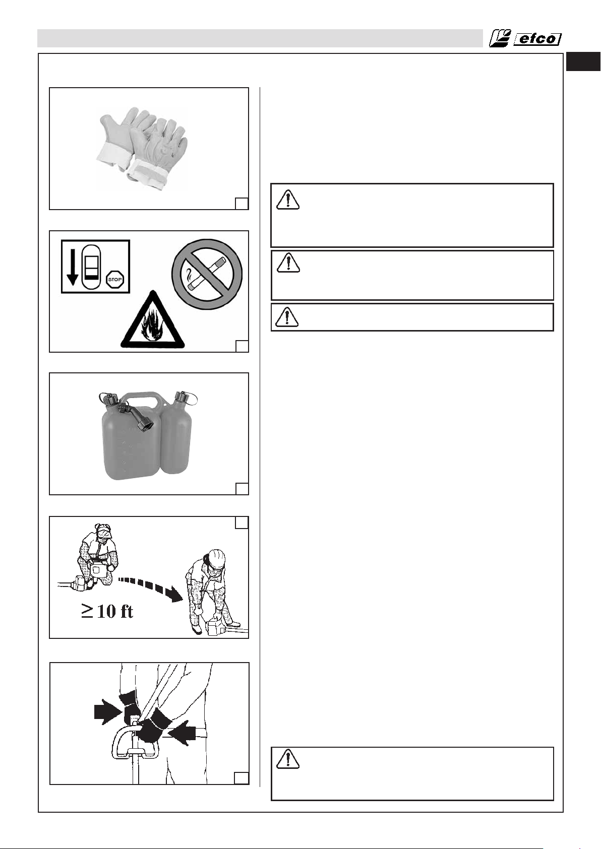
RÈGLES DE SÉCURITÉ
• Adressez-vous à un professionnel qualifié pour toute autre
intervention ne figurant pas dans le présent manuel.
• La débroussailleuse doit uniquement être utilisée pour la coupe
d'herbe, de mauvaises herbes et/ou de broussailles. Il est
fortement déconseillé de couper un autre type de matériau.
• Il est fortement déconseillé de raccorder à la prise de force de
la débroussailleuse tout outil ou accessoire non spécifié par le
fabricant.
Manipulation du carburant
AVERTISSEMENT : L'essence est un carburant
6
hautement inflammable. Manipulez l'essence ou le
mélange de carburant avec une extrême précaution.
Ne fumez pas ou ne produisez pas de source de
flamme à proximité du carburant ou de la
débroussailleuse (Fig.7).
AVERTISSEMENT : La respiration de vapeurs de
carburant ou leur contact avec la peau peut
provoquer des blessures graves. Il convient donc de
manipuler le carburant avec précaution et de
s'assurer d'opérer dans des endroits bien aérés.
AVERTISSEMENT : Soyez vigilant face au risque
d'empoisonnement au monoxyde de carbone.
fr
7
8
9
• Manipulez le carburant avec une extrême précaution afin
d'éviter tout risque d'incendie ou de brûlure. Le carburant
est hautement inflammable.
• Faites le mélange et transportez le carburant dans un
conteneur approuvé pour l'entreposage d'essence (Fig.8).
• Faites le mélange de carburant en extérieur, en l'absence de
toute source d'étincelles ou de flammes.
• Choisissez une surface dégagée, coupez le moteur et laissez
refroidir avant de faire le plein.
• Devissez lentement le bouchon de carburant afin de libérer la
pression et d'empêcher le carburant de s'écouler par le
bouchon.
• Resserrez fermement le bouchon de carburant après
remplissage. Sous l'effet des vibrations de la machine, un
bouchon mal refermé peut se desserrer, voire s'ouvrir,
entraînant un déversement du carburant.
• Essuyez toute trace de carburant sur la débroussailleuse et
attendez quelques secondes pour que les traces résiduelles
s'évaporent. Éloignez-vous de 3 m (10 ft) de la zone de remplissage avant de démarrer le moteur (Fig.9).
• Ne tentez en aucun cas de brûler le carburant déversé.
• Ne fumez pas en manipulant le carburant ou en utilisant la
débroussailleuse.
• Entreposez le carburant dans un endroit sec, frais et
suffisamment ventilé.
• Ne placez jamais la débroussailleuse sur un matériau
facilement inflammable, notamment sur des feuilles mortes, de
la paille, du papier, etc.
• Entreposez la machine et le carburant dans un endroit à l'abri
de toute source d'étincelles ou de flammes nues, de
chauffe-eau, de moteurs électriques, d'interrupteurs, de fours,
etc., susceptibles d'enflammer les vapeurs de carburant.
• Ne retirez jamais le bouchon du réservoir de carburant lorsque
le moteur tourne.
• N'utilisez jamais le carburant pour le nettoyage.
• Veillez à ne pas souiller vos vêtements de carburant. Si du
carburant est déversé sur une partie de votre corps ou sur vos
vêtements, changez-vous immédiatement. Rincez à l'eau et au
savon la partie de votre corps sur laquelle le carburant s'est
déversé.
• Ne pas exposer le réservoir d’essence aux rayons directs du
soleil.
• Garder le carburant hors de la portée des enfants.
10
Fonctionnement et sécurité
AVERTISSEMENT: Tenez toujours la
débroussailleuse à deux mains lorsque le moteur
tourne. Enserrer fermement les poignées de la
débroussailleuse entre les doigts et le pouce
(Fig.10).
39
Page 40
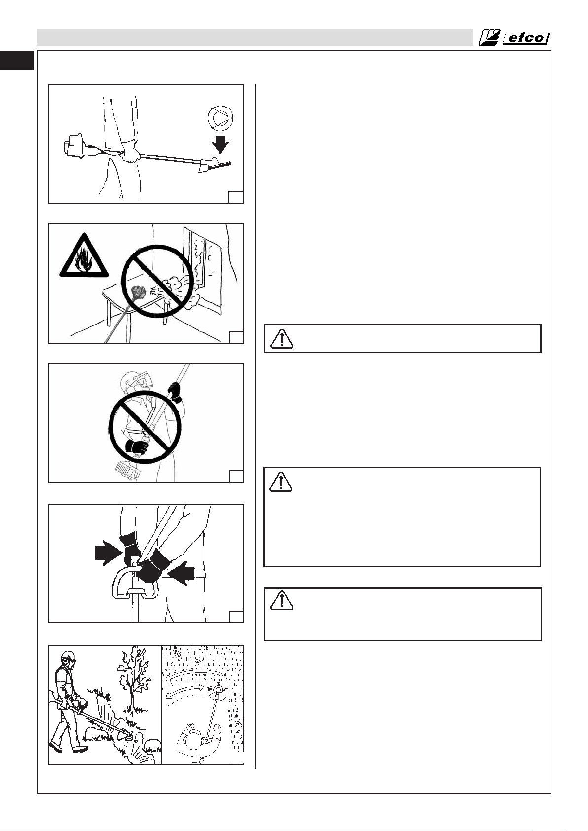
fr
RÈGLES DE SÉCURITÉ
• Tenez toutes les parties du corps à distance de l'outil de coupe
lorsque le moteur tourne.
• Transportez toujours la débroussailleusemoteur coupé et en
plaçant le silencieux d'échappement à distance de votre corps.
Transportez toujours la débroussailleuse avec son
protège-lame (Fig.11). Pour le transport à bord d'un véhicule,
protégez la lame avec le protège-lame. Fixez correctement la
débroussailleuse afin d'éviter qu'elle ne se renverse, que le
carburant ne s'écoule ou que la machine ne soit endommagée.
• N'utilisez jamais la débroussailleuse d'une seule main!
Une telle manipulation peut blesser gravement l'utilisateur ou
11
les personnes se tenant dans la zone de travail. Une
débroussailleuse s'utilise toujours à deux mains.
• Avant de démarrer le moteur, vérifiez que l'outil de coupe n'est
en contact avec aucun objet.
• Coupez le moteur avant de poser la débroussailleuse. Ne
laissez pas le moteur tourner sans surveillance.
• Utilisez exclusivement la débroussailleuse dans une zone suffisamment ventilée, ne l'utilisez pas dans un environnement
explosif ou inflammable ou dans des zones confinées (Fig.12).
Soyez vigilant face au risque d'empoisonnement au monoxyde
de carbone.
• N'utilisez pas la débroussailleuse sur une échelle ou
directement sur un arbre. Ayez toujours une assise stable et
une position appropriée.
12
13
14
AVERTISSEMENT : soyez vigilant lorsque vous travaillez sur des terrains en pente.
• N'effectuez aucune opération de coupe à proximité de câbles
électriques.
• Tenez vos mains au sec, propres et exemptes d'huile ou de
carburant.
• Ne travaillez jamais en plaçant la débroussailleuse au-dessus
de la hauteur d'épaules (Fig.13).
• N'utilisez jamais la débroussailleuse sans le protège-lame ou la
tête porte-lame.
• Ne démarrez pas le moteur sans le tube monté.
Mesures de précaution contre l'effet de rebond
AVERTISSEMENT : évitez tout phénomène de rebond
pouvant entraîner des blessures graves. L'effet de
rebond consiste en un mouvement brusque latéral
ou vers l'avant de la machine se produisant lorsque
la lame entre en contact avec un objet, tel qu'un rondin ou une pierre, ou lorsque la bille de bois se
referme et vient coincer la lame dans le plan de
coupe. Le contact avec un corps étranger dans le
bois peut également entraîner une perte de contrôle
de la débroussailleuse.
Comment réduire le risque de rebond
AVERTISSEMENT : vous devez admettre qu'il existe
toujours un risque de rebond. C'est par la
connaissance des bases du principe du rebond que
vous parviendrez à réduire l'effet de surprise
souvent attribué aux accidents.
40
15
• Ne laissez jamais la lame en mouvement venir au contact d'un
objet.
• Dégagez la zone de travail de tout objet encombrant, tel que les
arbres, branches, rochers, haies, souches, etc. Retirez ou
évitez tout objet susceptible de venir au contact de la lame lors
de la coupe.
• La lame de la débroussailleuse doit toujours être affûtée.
Suivez les instructions d'affûtage et d'entretien fournies par le
fabricant.
• Entamez et procédez à la coupe à plein régime. Le risque de
rebond est plus grand lorsque la lame tourne lentement.
Comment garder le contrôle (Fig.14-15)
• Tenez fermement la débroussailleuse à deux mains lorsque le
Page 41

RÈGLES DE SÉCURITÉ
moteur tourne et ne la lâchez pas. En maintenant fermement la débroussailleuse, vous réduirez le risque
de rebond et garderez le contrôler de la machine. Vos doigts doivent toujours enserrer la poignée.
• Tenez-vous sur vos deux pieds, le poids également réparti.
• Ne vous penchez pas trop, sous peine de perdre l'équilibre et le contrôle de la machine.
Fonctions de sécurité
AVERTISSEMENT : en tant qu'utilisateur, ne vous fiez pas uniquement aux fonctions de
sécurité de la machine. Vous devez scrupuleusement respecter les précautions de sécurité,
les instructions et les consignes d'entretien fournies dans le présent manuel afin d'éviter des
blessures graves.
AVERTISSEMENT : même correctement entretenus, le fonctionnement correct des fonctions
de sécurité sur le terrain ne peut être garanti.
Outils de coupe recommandés
fr
Réf. de pièce
1
4095605
2
4095597
3
4175157
4
63019007B
5
61172019
6
4180053
4180052
7
4180961
8
9A
4095638R
9B
10A
4095673R
10B
11A
4095674R
11B
12A
4095565R
12B
13
4095641R
Outils de coupe
Description
Lame nylon 3 dents, Ø 254 mm (10”)
Lame nylon 4 dents, Ø 254 mm (10”)
Tête “Pro Trim Universal” à 3 lames, Ø 304 mm (12”)
Tête “Tap’n go” à 2 fils en nylon, Ø 127 mm (5.1”)
avec fil de 2,7 mm (.11”)
Tête “Tap’n go” à 2 fils en nylon, Ø 127 mm (5.1”)
avec fil de 2,3 mm (.094”)
Tête universelle multifil, Ø 69 mm (2.75”)
avec 8 fils (3.3 mm) (0.13”)
Tête universelle multifil, Ø 69 mm (2.75”) avec 6 fils
(3,3 mm) (0.11”)
Tête universelle multifil, Ø 132 mm (5.2”) avec 8 fils
(2,7 mm) (0.11”)
Lame acier 3 dents, Ø 254 mm (10”), épaisseur de
1,2 mm (.05”)
Lame acier 3 dents, Ø 254 mm (10”), épaisseur de
1,7 mm (.07”)
Lame acier 3 dents, Ø 304 mm (12”), épaisseur de
2,2 mm (.09”)
Lame acier 8 dents, Ø 254 mm (9”), épaisseur de
1,2 mm (.05”)
Lame acier 3 dents, Ø 254 mm (10”), épaisseur de
2,7 mm (.11”)
Réf. de pièce
61170127
4174273A
4174273A
4174273A
61170127
4174273A
61170127
4174273A
61170127
4174273A
61170127
4174273A
61170127
4174273A
61170127
4174273A
4174273A
Protections
Description
Protection en plastique *
Protection en plastique *
Protection en plastique *
Protection en plastique
Protection en plastique
Protection en plastique
Protection en plastique
Protection en plastique
Protection en plastique *
Protection en plastique *
Protection en plastique *
Protection en plastique *
Protection en plastique *
Modèle
DS 2600 4S
DS 3600 4S
DS 3600 4S
DS 3600 4S
DS 2600 4S
DS 3600 4S
DS 2600 4S
DS 3600 4S
DS 2600 4S
DS 3600 4S
DS 2600 4S
DS 3600 4S
DS 2600 4S
DS 3600 4S
DS 2600 4S
DS 3600 4S
DS 3600 4S
*protection réf. 4174283A non requise
AVERTISSEMENT : l'utilisation de dispositifs de coupe non autorisés par le fabricant peut
entraîner un risque d'accident très élevé.
AVERTISSEMENT : les lames de scie circulaire ne doivent être utilisées avec le poignée
simple.
41
Page 42

fr
RÈGLES DE SÉCURITÉ
Vérification des dispositifs de sécurité
AVERTISSEMENT : n'utilisez jamais la machine si l'un des dispositifs de sécurité est
défectueux. Les dispositifs de sécurité de la machine doivent faire l'objet d'un contrôle et
d'un entretien spécifiques, comme décrit dans la présente section. Si le résultat de ces
vérifications est insatisfaisant, contactez le service après-vente pour faire réparer votre
machine.
Gâchette de verrouillage des gaz
La gâchette de verrouillage des gaz est conçue pour empêcher toute activation accidentelle de la
commande des gaz. Ce dispositif verrouille automatiquement la commande des gaz au ralenti.
Vérifiez que la commande des gaz est verrouillée au ralenti lorsque vous relâchez la gâchette.
Appuyez sur la gâchette de verrouillage des gaz et observez qu'elle retrouve sa position initiale une fois que
vous la relâchez.
Assurez-vous que la commande des gaz et la gâchette de verrouillage des gaz peuvent être actionnées
librement et que le ressort de rappel fonctionne correctement.
Interrupteur Marche/Arrêt
Utilisez l'interrupteur Marche/Arrêt pour arrêter le moteur.
Démarrez le moteur et assurez-vous qu'il s'arrête lorsque appuyez sur l'interrupteur en position Arrêt.
Protection de l'outil de coupe
Cette protection est conçue pour protéger l'utilisateur contre les risques de projection d'objets dans sa
direction. Elle sert également à prévenir tout contact accidentel avec l'outil de coupe.
Vérifiez que la protection n'est pas endommagée ou fissurée. Remplacez-la si elle présente des marques
d'impact ou des fissures.
Utilisez uniquement la protection appropriée à l'outil de coupe utilisé. Reportez-vous au chapitre relatif aux
caractéristiques techniques.
AVERTISSEMENT : n'utilisez jamais un outil de coupe sans la protection adéquate. Reportezvous à la section relative aux caractéristiques techniques.. L'utilisation d'une protection
inappropriée ou défectueuse peut entraîner des blessures corporelles graves.
Mesures de précaution pour réduire les risques liés aux vibrations
• La débroussailleuse est équipée d'un système anti-vibration (AV) que vous ne devez pas altérer ou
modifier.
• Portez des gants et tenez vos mains au chaud.
• Tenez toujours la lame affûtée et effectuez correctement l'entretien de la débroussailleuse, notamment le
système AV. Une lame émoussée augmente les vibrations transmises directement aux mains.
• Si vous utilisez un outil de coupe à bobine de fil, assurez-vous que le fil est correctement enroulé ; l'utilisation d'un outil coupe déséquilibré augmente considérablement le niveau de vibration.
• Maintenez fermement la débroussailleuse sans pour cela "écraser" les poignées en continu ; faites de
fréquentes pauses. Toutes les mesures de précautions citées ci-dessus ne garantissent pas que vous ne
souffrirez pas du syndrome des doigts morts ou canal carpien. Par conséquent, il est fortement
recommandé aux utilisateurs réguliers de surveiller l'état de leurs mains et de leurs doigts. En cas d'apparition de l'un des symptômes précédemment cités, consultez immédiatement un médecin.
Précaution d'entretien
AVERTISSEMENT : n'utilisez jamais une débroussailleuse endommagée, mal réglée, ou
mal/partiellement montée.
• Vérifier que l'outil de coupe s'arrête lorsque vous relâchez la gâchette des gaz. Si l'outil de coupe tourne
au ralenti, un réglage du carburateur peut être nécessaire (voir la section Fonctionnement - Réglage du
carburateur). Si le problème persiste après le réglage du carburateur, contactez un réparateur et cessez
d'utiliser la machine jusqu'à sa réparation.
42
AVERTISSEMENT : hormis les instructions d'entretien fournies par le Manuel d'utilisation,
toutes les autres procédures d'entretien de la débroussailleuse doivent être effectuées par
un personnel de maintenance qualifié. (En cas d'utilisation d'outils non appropriés pour le
démontage du volant-moteur ou de l'embrayage ou pour le maintien du volant-moteur en vue
du démontage de l'embrayage, le volant-moteur peut subir des dégâts structurels à l'origine
de son éclatement pouvant causer de graves blessures.)
Page 43

RÈGLES DE SÉCURITÉ
• Ne modifiez en aucune façon les caractéristiques de votre débroussailleuse.
• Tenez vos mains au sec, propres et exemptes d'huile ou de carburant.
AVERTISSEMENT : utilisez exclusivement des accessoires et des pièces de rechange
préconisés..
• Ne touchez jamais l'outil de coupe ou n'effectuez jamais l'entretien sur la machine lorsque le moteur
tourne.
• N'utilisez jamais le carburant pour le nettoyage.
• La débroussailleuse doit être entreposée dans un local sec, au-dessus du niveau du sol, la lame étant
munie de sa protection et le réservoir de la machine entièrement vidé.
• Lorsque la débroussailleuse atteint la fin de sa vie utile, mettez-la au rebut conformément à la
réglementation en vigueur en matière de protection de l'environnement en la ramenant à votre distributeur local qui suivra la procédure appropriée pour ce type de machine.
• Remplacez immédiatement tout dispositif de sécurité endommagé ou cassé.
AVERTISSEMENT : le silencieux ainsi que d'autres pièces du moteur (notamment les ailettes
du cylindre, la bougie d'allumage) atteignent des températures très élevées en
fonctionnement et après arrêt de la machine. Afin de réduire les risques de brûlure, ne touchez pas le silencieux ou les autres pièces lorsqu'elles sont encore chaudes.
fr
43
Page 44

fr
ASSEMBLAGE
Montage du poignée simple
• Montez la poignée sur le tuyau de transmission et fixez-la avec
les vis (A, Fig. 16), les rondelles et les écrous. La position de la
poignée se règle selon les exigences de l’opérateur.
Montage de la protection de l'outil de coupe
16
18
Montage de la protection de sécurité (Fig.18-19)
Fixez le protège-lame (A) au tube à l'aide des vis (B) de façon à
pouvoir travailler en toute sécurité..
REMARQUE : montez la protection de coupe (C, Fig.18)
lorsque vous utilisez des têtes à fil en nylon. Fixez la protection de coupe (C) à la protection (A) à l'aide de la vis (D).
AVERTISSEMENT : Jamais vous utilisez des disques
à bois.
AVERTISSEMENT : n'utilisez jamais un outil de
coupe sans la protection adéquate. Reportez-vous à
la section Outils de coupe recommandés (Page 41).
L'utilisation d'une protection inappropriée ou
défectueuse peut entraîner des blessures corporelles graves.
AVERTISSEMENT : le déflecteur fourni avec la
débroussailleuse peut ne pas protéger totalement
l'utilisateur des différents objets (gravier, verre,
câbles, etc.) susceptibles d'être projetés par l'outil de
coupe en mouvement. Les objets projetés peuvent
aussi ricocher et blesser l'utilisateur.
19
20
AVERTISSEMENT : remplacez immédiatement toute
protection cassée ou endommagée ; ne tentez jamais
de monter la protection dans une position autre que
la sienne.
Montage de la protection de l'outil de coupe
AVERTISSEMENT : lors du montage de l'outil de
coupe, il est primordial que la bride d'entraînement
s'engage correctement dans l'orifice central de
l'outil de coupe. Le montage incorrect de l'outil de
coupe peut entraîner des blessures corporelles
graves et/ou mortelles.
44
Page 45

21
ASSEMBLAGE
fr
AVERTISSEMENT : utilisez exclusivement les outils
de coupe avec les protections recommandées !
Reportez-vous au chapitre Outils de coupe
recommandés (Page 41). Reportez-vous aux
instructions fournies avec l'outil de coupe pour vérifier le bon montage du fil et le diamètre approprié de
ce dernier. Les dents de la lame doivent être correctement affûtées ! Suivez nos recommandations.
Reportez-vous également aux instructions
mentionnées sur l'emballage de la lame. Les spécifications correctes de la lame doivent être respectées
! Suivez nos instructions.
AVERTISSEMENT : arrêtez systématiquement le
moteur avant d'intervenir de quelque façon que ce
soit sur l'outil de coupe. L'outil de coupe continue de
tourner lorsque la commande des gaz est relâchée.
Veillez à ce que l'outil de coupe soit complètement
arrêté et débranchez le câble de la bougie avant toute
intervention.
AVERTISSEMENT : l'utilisation d'un outil de coupe
inapproprié ou d'une lame mal affûtée augmente le
risque de rebond.
22
AVERTISSEMENT : débarrassez-vous
systématiquement des lames pliées, tordues,
fissurées, cassées ou endommagées de quelque
autre façon (Fig.19, page 44). Ne tentez jamais de
redresser une lame tordue pour la réutiliser. Utilisez
exclusivement des lames d'origine, du type spécifié.
23
24
AVERTISSEMENT : pour réduire le risque de
blessures graves, n'utilisez jamais de fil câblé ou à
renfort métallique ou tout autre matériau à la place
du fil de coupe en nylon. Les fils câblés peuvent se
rompre et être projetés à grande vitesse en direction
de l'utilisateur ou de passants.
Montage de la tête de coupe à fils (20, page 44-Fig.21)
Mettez la bride supérieure (A) en place. Appuyez sur le bouton de
fixation de la tête (B) et serrez celle-ci (C) en la vissant, à la main,
dans le sens inverse des aiguilles d'une montre.
Montage de la lame (Fig.22-23)
Dévissez l'écrou (A) dans le sens des aiguilles d'une montre ;
retirez le carter (B) et la bride inférieure (C). Montez la lame (D)
sur la bride supérieure (E), en vérifiant que le sens de rotation est
correct. Montez la bride inférieure (C), le carter (B) et vissez
l'écrou (A) dans le sens contraire des aiguilles d'une montre.
Appuyez sur le bouton de fixation (F) pour bloquer la lame et
serrer l'écrou à 25 Nm (18.4 ftlb).
AVERTISSEMENT : les flèches figurant sur la
protection de l'outil de coupe (Fig.24) indiquent le
sens de rotation correct de l'outil de coupe.
AVERTISSEMENT : montez le protège-lame (M),
référence 4196086, comme illustré (Fig.25) avant de
transporter ou de remiser la débroussailleuse.
25
MISE EN GARDE : n'utilisez jamais la
débroussailleuse sans le carter (B, Fig.22-23) sous
peine d'endommager le filetage.
45
Page 46

fr
FONCTIONNEMENT
AVERTISSEMENT : ne touchez ou ne réglez jamais la
lame alors que le moteur tourne. La lame est un outil
très affûté, il convient donc de toujours porter des
gants de protection avant toute intervention.
AVERTISSEMENT : le pignon, conique peut devenir
très chaud après l'utilisation de la machine, il
convient donc de toujours porter des gants de protection avant toute intervention.
26
27
28
Alimentation en carburant (Interdiction de fumer !) (Fig.28)
Ce produit est équipé d'un moteur 4 temps. Remisage l'essence
sans plomb dans un conteneur propre et adapté pour l'essence
(Fig.26).
CARBURANT RECOMMANDÉ :CE MOTEUR EST CERTIFIÉ
POUR FONCTIONNER AVEC DE L'ESSENCE SANS PLOMB
POUR USAGE AUTOMOBILE PRÉSENTANT UN INDICE
D'OCTANE DE 89 ([R + M] / 2) OU SUPÉRIEUR (Fig.27).
Ne jamais utiliser de l’essence ou un mélange d’huile/essence
viciés ou contaminés. Empêcher la pénétration de saleté ou eau
dans le réservoir de carburant.
NOTE :
L’essence se dégrade très rapidement sous l’effet de facteurs tels
que l’exposition à la lumière, température et temps.
Dans le pire des cas, elle peut être contaminée en moins de 1
mois.
L’utilisation d’essence contaminée peut endommager sérieusement le moteur (obstruction du carburateur, grippage des soupapes).
La garantie ne couvre pas les dommages dus à un carburant
dégradé.
Pour éviter ceci, observer rigoureusement ces recommandations:
• N’utiliser que l’essence spécifiée.
• Pour ralentir la dégradation, conserver l’essence dans un récipient de carburant certifié.
• Avant un long remisage (plus de 1 mois, vidanger le réservoir
de carburant et le carburateur.
ESSENCES CONTENANT DE L’ALCOOL
En cas d’utilisation d’une essence contenant de l’alcool (‘‘gazole’’), s’assurer que son indice d’octane est au moins égal à l’indice recommandé par Emak. Il existe deux types de gazole : le premier contient de l’éthanol, le second du méthanol. Ne pas utiliser
de gazole contenant plus de 10% d’éthanol. Ne pas utiliser une
essence contenant du méthanol (alcool méthylique ou alcool de
bois) sans cosolvants et inhibiteurs de corrosion pour méthanol.
Ne jamais utiliser une essence contenant plus de 5% de méthanol, même si elle contient des cosolvants et des inhibiteurs de corrosion.
NOTE :
• Les dommages du circuit d’alimentation ou les problèmes de
performances du moteur résultant de l’utilisation de carburants
contenant de l’alcool ne sont pas couverts par la garantie.
Emak n’est pas en mesure d’approuver l’utilisation de carburants contenant du méthanol, car la preuve de leur adéquation
n’est pas encore pleinement faite.
• Avant de se ravitailler dans une station-service que l’on connaît
mal, essayer de savoir si l’essence contient de l’alcool, quel est
le type d’alcool utilisé et dans quel pourcentage. En cas d’anomalie de fonctionnement après avoir utilisé une essence contenant de l’alcool ou une essence que l’on suspecte d’en contenir, revenir à une essence sans alcool.
46
Page 47

FONCTIONNEMENT
fr
29
30
Remplissage du réservoir
AVERTISSEMENT : respectez les mesures de
sécurité pour la manipulation du carburant. Coupez
toujours le moteur avant d'approvisionner la
machine en carburant. Ne faites jamais l'appoint de
carburant alors que le moteur tourne ou s'il est encore chaud. Déplacez-vous à au moins 3 mètres de la
zone de remplissage avant de démarrer le moteur
(Fig.29). NE FUMEZ PAS !
1. Nettoyez la surface autour du bouchon de carburant afin
d'éviter toute contamination..
2. Dévissez lentement le bouchon de carburant.
3. Versez le carburant dans le réservoir avec précaution. Évitez
de renverser du carburant.
4. Avant de remonter le bouchon de carburant, nettoyez et
inspectez le joint d'étanchéité.
5. Remontez et serrez immédiatement le bouchon de carburant.
Essuyez tout déversement de carburant.
REMARQUE : lors de sa première utilisation, un moteur émet
une certaine quantité de fumée. Cela est normal.
AVERTISSEMENT : contrôlez la présence éventuelle
de fuites de carburant, et rectifiez le cas échéant.
Contactez un réparateur agréé si nécessaire.
31
32
Réservoir d’huile moteur
1. Niveau d’huile moteur
MISE EN GARDE :
• Faire tourner le moteur avec une quantité insuffisante d’huile peut très sérieusement l’endommager.
• Pour vérifier le moteur, l’arrêter et le placer sur une
surface horizontale.
1. Enlever le bouchon de remplissage d’huile (A, Fig.30) et véri-
fier le niveau d’huile; il doit atteindre le haut du goulot de dispositif de remplissage d’huile (B).
2. Si le niveau est bas, faire le plein jusqu’au haut de la tubulure
de remplissage d’huile (C, Fig.31) avec de l’huile recomman-
dée.
Verser l’huile moteur progressivement pour éviter son débordement, car le réservoir d’huile moteur est petit.
Vérifier le niveau d’huile toutes les 10 heures et faire l’appoint
d’huile jusqu’au haut du goulot de remplissage d’huile. Si le
moteur est utilisé de manière continue pendant plus de 10 heures.
Utiliser de l’huile Efco 4 temps ou une huile moteur équivalente,
hautement détergente et de première qualité, certifiée conforme
ou supérieure aux exigences des constructeurs automobiles américains pour la classification des services SG, SF. Les huiles
moteur classées SG, SF porteront cette indication sur le bidon.
L’huile SAE10W-30 est recommandée pour un usage général,
toute température.
MISE EN GARDE : L’utilisation d’une huile moteur
non détergente ou 2 temps peut augmenter la fréquence d’entretien du moteur.
47
Page 48

fr
FONCTIONNEMENT
La plage des températures de fonctionnement recommandée
pour ce moteur est de –5 °C à 40 °C (23 °F à 104 °F).
Préparation à la coupe
AVERTISSEMENT : si vous utilisez des lames rigides,
évitez les travaux de coupe à proximité des clôtures,
des bâtiments, des troncs d'arbre, des rochers ou
d'autres objets similaires susceptibles d'entraîner un
33
34
effet de rebond de la débroussailleuse ou
d'endommager la lame. Nous recommandons l'utilisation de tête à fils nylon pour ces travaux. En outre,
dans ces situations, le risque de ricochet est
considérablement accru.
AVERTISSEMENT : la débroussailleuse s'utilise
normalement au niveau du sol, l'outil de coupe
devant être parallèle à celui-ci. L'utilisation de la
machine au-dessus du sol ou avec l'outil de coupe
perpendiculaire à celui-ci augmente le risque de
blessure, dans la mesure où l'outil de coupe est
totalement exposé et où la débroussailleuse peut
s'avérer plus difficile à contrôler. N'utilisez jamais la
débroussailleuse comme taille-haie.
35
36
AVERTISSEMENT : si la lame se desserre après avoir
été correctement réglée, arrêtez le travail
immédiatement. Il est possible que la vis de fixation
soit usée ou abîmée et il faut la remplacer. N'utilisez
jamais des pièces non autorisées pour fixer la lame.
Si le problème persiste, contactez votre distributeur.
N'utilisez jamais la débroussailleuse avec une lame
mal fixée.
Méthode de coupe de base
1. Portez des gants antidérapants pour une adhérence et une protection optimales.
AVERTISSEMENT : tenez toujours la débroussailleuse à deux mains (Fig. 33, page 47). Votre corps doit
toujours se tenir à gauche du tube. Vous devez maintenir la débroussailleuse à deux mains, sans jamais
les croiser. Ces directives s'appliquent également
aux gauchers.
Conservez la position de coupe correcte (Fig. 34,
page 47).
2. Gardez une bonne prise en main (Fig. 33) de la débrous-
sailleuse lorsque le moteur tourne. Les doigts doivent venir
enserrer la poignée et le pouce s'enrouler sous la poignée.
48
37
Mise en place du harnais
Un bon réglage du système de courroies permet à la débroussailleuse d'avoir un bon équilibre et d'être à une hauteur du sol
adéquate (Fig.35).
• Enfiler la courroie simple.
• Accrocher la débroussailleuse à la courroie à l'aide du crochet
(A, Fig.36).
• Positionner le crochet (B, Fig.36) de manière à obtenir le
meilleur équilibre pour la débroussailleuse.
• Placer la boucle (C, Fig.37) de manière à ce que la débrous-
sailleuse soit à la bonne hauteur.
Page 49

FONCTIONNEMENT
fr
38
Équilibrage correct (Fig. 36)
1. Débroussaillage
L'équilibrage de la machine s'obtient en poussant la bague de
maintien vers l'avant ou l'arrière. Sur certains modèles, cette
bague est fixe, mais un certain nombre d'orifices sont prévus
pour fixer le crochet. La machine est correctement équilibrée
lorsqu'elle reste suspendue au crochet à l'horizontale. Ce
réglage limite le risque de contact avec des rochers ou des
pierres si vous êtes amené à lâcher le guidon.
2. Coupe d'herbe
Équilibrez la machine de sorte que la hauteur de coupe soit
appropriée, c'est-à-dire avec la lame près du sol.
Précautions relatives à la zone de travail
AVERTISSEMENT : ne coupez que de l'herbe ou des
mauvais herbes. Pour la coupe de bois, utilisez une
lame de scie circulaire appropriée. Ne coupez ni
métaux, ni plastiques, ni pièces de maçonnerie ou
tout autre matériau qui ne serait pas dérivé du bois.
• Ne laissez jamais un enfant utiliser la débroussailleuse. Toute
autre personne susceptible d'utiliser la débroussailleuse doit
avoir préalablement lu le présent Manuel d'utilisation ou avoir
pris connaissance des instructions appropriées à une
utilisation correcte et en toute sécurité de cette
débroussailleuse.
• Maintenez toute personne (assistant, entourage, enfants et
animaux) à une distance de sécurité de la zone de coupe
(Fig.38). Pendant le travail de coupe, maintenez une distance
d'au moins 15 m (50 ft) entre les travailleurs.
• Gardez en permanence les deux pieds sur une assise stable
de façon à éviter toute perte d'équilibre.
• Assurez-vous de toujours pouvoir vous mouvoir en toute
sécurité. Inspectez la zone de travail et dégagez tout obstacle
éventuel (racines, rochers, branches, fossés, etc.) pour le cas
où vous devriez vous déplacer rapidement. Prenez toutes les
précautions nécessaires sur les terrains en pente.
• Ne coupez pas au-dessus de la hauteur de poitrine, car il est
toujours plus difficile de contrôler une débroussailleuse placée
en hauteur en cas de rebond.
• Ne travaillez pas à proximité de lignes électriques. Laissez agir
des professionnels dans de pareilles situations.
• Ne procédez à des travaux de coupe que si la visibilité et la
luminosité vous permettent d'y voir clairement.
• N'utilisez pas la débroussailleuse sur une échelle ; cela est
extrêmement dangereux.
• Arrêtez immédiatement la débroussailleuse si la lame entre en
contact avec un objet. Inspectez le dispositif de coupe et
procédez à la réparation des pièces endommagées si
nécessaire.
• Évitez tout contact de la lame avec des débris ou du sable.
Même une très faible quantité de débris peut très rapidement
émousser une lame et augmenter le risque de rebond.
• Coupez le moteur avant de reposer la débroussailleuse.
• Soyez particulièrement vigilant lorsque vous portez des
protections anti-bruit car de tels équipements réduisent la
capacité d'entendre les signaux sonores d'avertissement en
cas de danger (tels que cris, alarmes et avertissements, etc.).
• Soyez extrêmement vigilant lorsque vous travaillez en pente ou
sur des surfaces irrégulières.
49
Page 50

fr
FONCTIONNEMENT
39
40
40
AVERTISSEMENT : n'utilisez jamais de lames rigides
pour les travaux de coupe dans des zones
rocheuses. Les projections et l'utilisation de lames
endommagées peuvent être à l'origine de blessures
corporelles grave, voire mortelles, pour l'utilisateur
ou les passants. Soyez très vigilant et méfiez-vous
des projections. Portez toujours des lunettes de
sécurité. Ne vous penchez jamais au-dessus de la
protection de l'outil de coupe. Des pierres ou des
débris peuvent être projetés au niveau des yeux, ce
qui peut entraîner des blessures graves, voire la
cécité. Maintenez toute personne non autorisée à
une distance de sécurité. Maintenez les enfants, les
animaux, les observateurs et les assistants à une
distance minimale de 15 mètres (50 ft) de la zone de
sécurité. À l'approche d'un tiers, arrêtez
immédiatement la machine. N'appliquez jamais un
mouvement circulaire à la machine sans vous être
préalablement assuré- de l'absence de toute personne dans la zone de sécurité.
AVERTISSEMENT : n'effectuez jamais à un travail de
coupe par faible visibilité ou par températures
extrêmement élevées ou basses, ou par grandes
gelées.
Démarrage du moteur
AVERTISSEMENT : au démarrage du moteur, avec
l'étrangleur en position d'étranglement ou d'accélérateur de démarrage, l'outil de coupe commence
immédiatement à tourner.
41
42
• Placez la débroussailleuse au niveau du sol et inspectez la
zone de travail pour vous assurer qu'aucun objet ou obstacle
ne risque d'entrer en contact avec l'outil de coupe. Maintenez
le corps de la machine vers le sol avec votre main gauche
(ATTENTION ! Jamais avec le pied !), voir Fig.39.
• Actionnez lentement la poire d'amorçage 6 à 8 fois (A, Fig.40).
• Tirer le levier de l'accélérateur (C, Fig.41) et mettre l'interrup-
teur (B) sur pour bloquer en demi-accélération; puis relâcher le levier (C).
• Tirez le levier d'étrangleur (D, Fig.42) de façon à l'amener en
position FERMER (CLOSE).
• Tirez sur le lanceur (Fig.39) jusqu'à entendre le premier
allumage du moteur (pas plus de cinq (5) tractions). Il est
possible qu'une machine neuve nécessite des tentatives
de lancement supplémentaires.
• N'enroulez jamais le lanceur autour de votre main.
• Aux premières détonations du moteur, déplacer progressivement la levier du starter (D, Fig.43) vers la position “OPEN”
(ouvert).
• Une fois parti, appuyer sur l'accélérateur (C, Fig.41) afin qu'il
sorte de sa position de demi-accélération et faire tourner le
moteur au ralenti. Chauffer le moteur jusqu’à ce qu’il tourne
régulièrement.
• Lorsque vous tirez sur le lanceur, n'utilisez pas toute la
longueur de la corde au risque de la briser. Ne laissez pas le
lanceur claquer sans l'accompagner au retour. Maintenez la
poignée et laissez la corde s'enrouler lentement.
50
AVERTISSEMENT : N’utiliser le dispositif demi-accélération que dans la phase de démarrage du moteur
à froid.
43
Page 51

FONCTIONNEMENT
En cas de mise en marche à chaud du moteur, l’interrupteur (E)
doit être positionné comme indiqué sur la Fig.44.
AVERTISSEMENT : ne procédez pas à la coupe avec
le levier d'étrangleur/de ralenti accéléré en position
FERMER. N'utilisez pas votre débroussailleuse
lorsque le blocage d'accélérateur est appliqué. Le
fait de travailler avec le blocage d'accélérateur de
démarrage engagé ne permet pas à l'utilisateur de
contrôler correctement la débroussailleuse.
REMARQUE - DÉMARRAGE D'UN MOTEUR CHAUD :
44
Suivez les instructions pour le démarrage, mais n'utilisez pas
la position FERMER maximal pour redémarrer le moteur.
AVERTISSEMENT : les conditions climatiques et
l'altitude peuvent affecter la carburation. Tenez les
tierces personnes à distance de la débroussailleuse
lors du réglage du carburateur.
Maintenez le régime moteur maximal pendant toute la durée de la
coupe.
Utilisation à haute altitude
fr
45
46
47
À haute altitude, le mélange Standard air-carburant du carburateur est trop riche. Les performances du moteur diminuent et la
consommation de carburant augmente.
Les performances à haute altitude peuvent être améliorées grâce
à certaines modifications du carburateur. Si le moteur doit fonctionner en permanence à une altitude supérieure à 1,500 m
(5,000 pieds), demander à un concessionnaire Efco agréé d’apporter ces modifications au carburateur.
Même avec un réglage correct de la carburation, la puissance du
moteur diminue d’environ 3,5 % pour chaque augmentation d’altitude de 300 m (1,000 pieds). L’effet de l’altitude sur la puissance
est encore plus important si aucune modification du carburateur
n’est effectuée.
MISE EN GARDE : L’utilisation du moteur à une altitude inférieure à celle pour laquelle le carburateur
est prévu peut entraîner une réduction des performances, une surchauffe et un endommagement
grave du moteur, du fait que le mélange air-carburant
sera trop pauvre.
Rodage du moteur
Le moteur atteint sa puissance maximale après 5 à 8 heures de
fonctionnement.
Au cours de cette période de rodage, ne laissez pas tourner la
machine à vide à plein régime de façon à éviter toute contrainte
inutile.
ATTENTION ! Au cours de la périodede rodage, ne
modifiez pas la carburation sous prétexte d'obtenir
une augmentation de la puissance ; vous risquez
uniquement d'endommager le moteur.
Démarrage difficile (ou démarrage d'un moteur noyé)
Vous pouvez noyer le moteur par une alimentation en carburant
trop importante si le moteur ne démarre pas après avoir actionné
10 fois le lanceur. Il est possible d'éliminer l'excès de carburant
d'un moteur noyé en suivant la procédure de démarrage d'un
moteur chaud décrite ci-dessus. Vérifiez que 'interrupteur de
marche/arrêt est en position de marche (ON). Le démarrage peut
nécessiter un grand nombre d'actionnements du lanceur en
fonction de l'importance du noyage du moteur. Si vous ne
parvenez pas à démarrer le moteur, reportez-vous au TABLEAU
DE DIAGNOSTIC DES PANNES (page 62).
51
Page 52
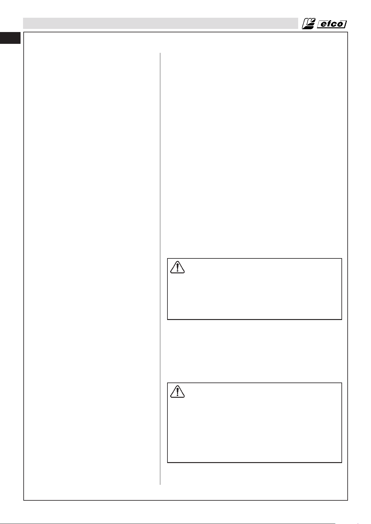
fr
FONCTIONNEMENT
Moteur noyé
• Basculez l'interrupteur de marche/arrêt sur la position STOP.
• Dévissez la vis située sur le couvercle (1, Fig.45).
• Retirez le couvercle (2).
• Insérez un outil adapté dans la coiffe de bougie (3, Fig. 46).
• Faites levier sur la coiffe de bougie et retirez-la.
• Dévissez et séchez la bougie.
• Ouvrez l'accélérateur à fond.
• Actionnez le lanceur à plusieurs reprises de façon à vider la
chambre de combustion.
• Remontez la bougie et connectez la coiffe en l'enfonçant
fermement. Remontez les autres pièces.
• Basculer l'interrupteur de marche/arrêt sur I, la position de
démarrage.
• Passez le levier d'étrangleur sur la position OUVRIR, même si
le moteur est froid.
• Démarrez à présent le moteur.
Arrêt du moteur
Relâchez la gâchette des gaz (C, Fig.47) et laissez le moteur
tourner au ralenti. Pour couper le moteur, basculez l'interrupteur
de marche/arrêt (B) sur la position STOP. Ne reposez pas la
débroussailleuse tant que l'outil de coupe est encore en
mouvement.
Au cas où la position “ STOP ” de l'interrupteur ne fonctionnerait
pas, coupez le moteur en ramenant le levier d'étrangleur sur la
position FERMER (Fig.42).
Contrôle avant utilisation
AVERTISSEMENT : L'OUTIL DE COUPE NE DOIT
JAMAIS TOURNER AU RALENTI. Tournez la vis de
réglage du ralenti “T” dans le sens inverse des
aiguilles d'une montre pour réduire le régime de
ralenti ou contactez un réparateur agréé pour
procéder au réglage ; n'utilisez pas la machine avant
que la réparation n'ait été effectuée.
Des blessures corporelles graves peuvent résulter
du fonctionnement au ralenti de l'outil de coupe.
Un embrayage défectueux peut être à l'origine du mouvement au
ralenti de l'outil de coupe et augmenter le risque de blessure
corporelle lié à la perte de contrôle de la machine ou au contact
accidentel avec l'outil de coupe.
Techniques de travail
Instructions générales de travail
AVERTISSEMENT :cette section décrit les
précautions de sécurité de base applicables au
travail avec des lames de scie circulaire ou des têtes
de coupe à fils. Si vous vous trouvez dans une
situation pour laquelle vous avez des doutes quant à
la technique à adopter, demandez conseil auprès
d'un spécialiste. Contactez votre distributeur ou le
service d'assistance. N'entreprenez pas un travail
que vous jugez au-delà de vos capacités. Avant de
commencer, il est important de connaître les
différences qui existent entre le débroussaillage, le
désherbage et la coupe d'herbe.
52
Règles de sécurité de base
1. Inspectez la zone où vous comptez travailler :
• Assurez-vous qu'aucune personne, animal ou aucun autre
élément ne risque d'affecter votre contrôle de la machine.
Page 53

FONCTIONNEMENT
• Assurez-vous qu'aucune personne ni aucun animal, etc.,
ne risque d'entrer en contact avec l'outil de coupe ou d'être
blessé par les objets pouvant être projetés par l'outil de
coupe.
AVERTISSEMENT : n'utilisez pas la machine si vous
n'êtes pas en mesure de pouvoir appeler à l'aide en
cas d'accident.
2. N'utilisez pas la machine dans de mauvaises conditions météo
(épais brouillard, forte pluie, vent violent, froid extrême, etc.).
48
49
Travailler dans de mauvais conditions météo est très fatigant et
peut accroître les risques d'accident en raison d'un sol gelé ou
d'un sens d'abattage imprévisible, etc.
3. Assurez-vous de toujours pouvoir vous mouvoir en toute
sécurité. Inspectez la zone de travail et dégagez tout obstacle
éventuel (racines, rochers, branches, fossés, etc.) pour le cas
où vous devriez vous déplacer rapidement. Soyez très vigilant
lorsque vous travaillez sur des terrains en pente.
4. Arrêtez le moteur avant de changer de zone de travail.
5. Ne reposez jamais la machine lorsque le moteur tourne.
• Utilisez toujours l'équipement approprié.
• Veillez au bon réglage de l'équipement.
• Respectez les précautions de sécurité.
• Organisez méticuleusement votre travail.
• Utilisez toujours l'étranglement maximum au début des
travaux de coupe avec une lame.
• Utilisez toujours des lames bien affûtées.
• Évitez les pierres.
fr
50
AVERTISSEMENT : ni l'utilisateur ni aucune autre
personne ne doit tenter de démonter l'outil de coupe
lorsque le moteur tourne ou que l'outil de coupe est
en mouvement, car des blessures graves peuvent en
résulter. Arrêtez le moteur et l'outil de coupe avant de
procéder au retrait de débris enroulés autour de la
lame car cette opération présente un risque élevé de
blessure. Le pignon conique peut devenir très chaud
après l'utilisation de la machine et le rester un
certain temps. Ne le touchez pas, sous peine de vous
brûler.
AVERTISSEMENT : soyez très vigilant et méfiez-vous
des projections. Portez toujours des lunettes de
sécurité. Ne vous penchez jamais au-dessus de la
protection de l'outil de coupe. Des pierres ou des
débris peuvent être projetés au niveau des yeux, ce
qui peut entraîner des blessures graves, voire la
cécité. Maintenez toute personne non autorisée à
une distance de sécurité. Maintenez les enfants, les
animaux, les observateurs et les assistants à une
distance minimale de 15 mètres de la zone de
sécurité. À l'approche d'un tiers, arrêtez
immédiatement la machine. N'appliquez jamais un
mouvement circulaire à la machine sans vous être
préalablement assuré de l'absence de toute
personne dans la zone de sécurité.
AVERTISSEMENT : des branches ou de l'herbe
peuvent se bloquer entre la protection et l'outil de
coupe. Arrêtez toujours le moteur avant de procéder
au nettoyage.
Vérifiez le dispositif de coupe avant d'allumer la machine.
• Vérifiez la lame et assurez-vous qu'aucune fissure ne s'est
formée à la base des dents ou au niveau de l'orifice central.
Débarrassez-vous de la lame si vous observez des fissures.
(Fig.48)
• Vérifiez que la bride de maintien n'est pas fissurée en raison de
l'usure ou d'un serrage excessif. Débarrassez-vous de la bride
si elle est fissurée. (Fig.49)
• Assurez-vous que l'écrou de verrouillage n'a pas perdu sa force
de captation. Le couple de serrage de l'écrou de fixation doit
être de 25 Nm. (18.4 ftlb)(Fig.49)
• Vérifiez que le protège-lame n'est pas endommagé ou fissuré.
Remplacez-le s'il est fissuré. (Fig.50)
53
Page 54
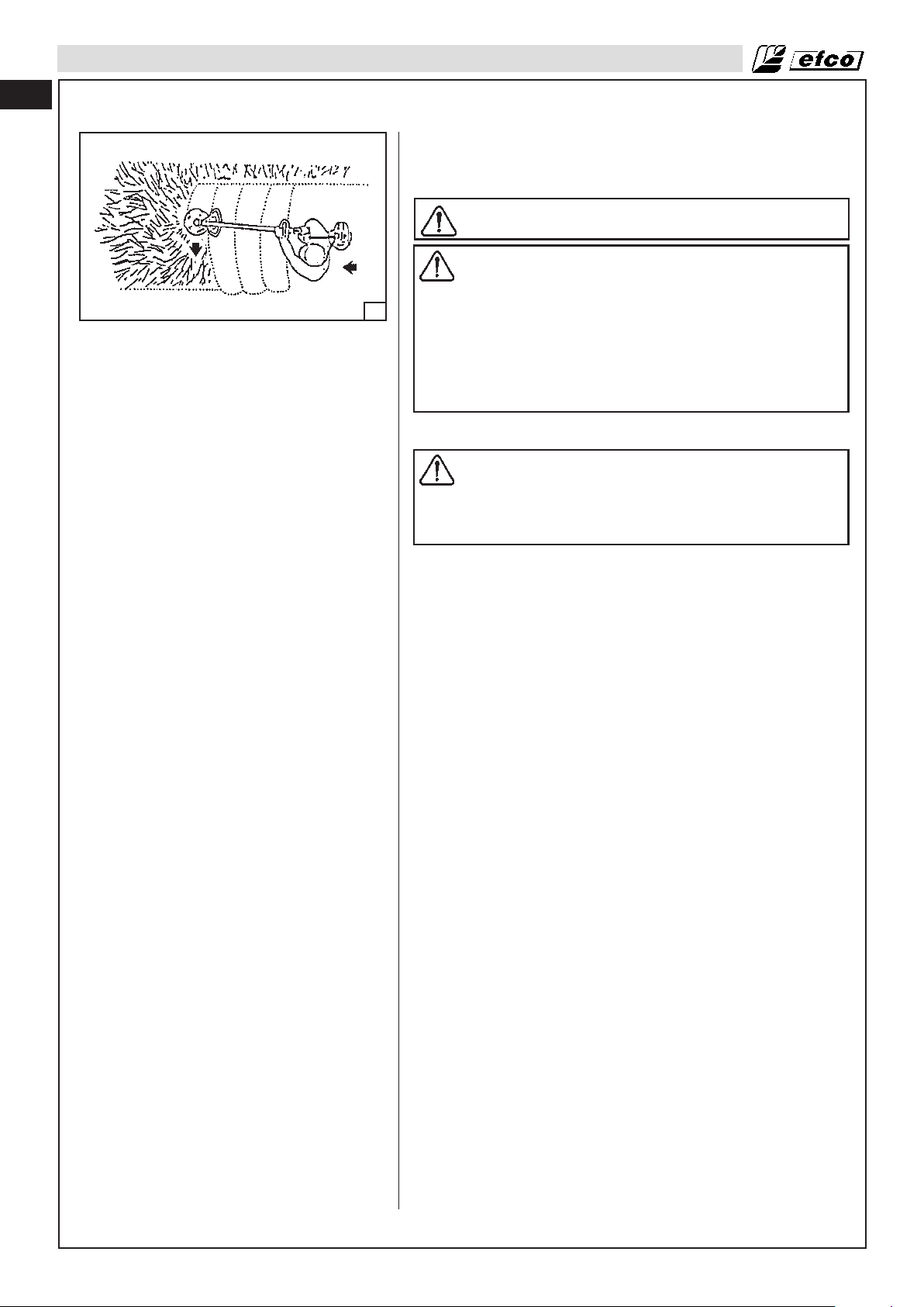
fr
FONCTIONNEMENT
• Vérifiez que la tête de coupe à fils et que sa protection ne sont
pas endommagées ou fissurées. Remplacez la tête de coupe à
fils ou la protection si l'une ou l'autre présente des fissures.
(Fig.50)
AVERTISSEMENT : n'utilisez jamais la machine sans
protection ou déflecteur.
AVERTISSEMENT : le couvercle d'embrayage et le
tube doivent être complètement montés avant la
mise en route de la machine, sous peine de détendre
51
Méthodes de travail
l'embrayage et d'entraîne un risque élevé de
blessure.
Assurez-vous que l'outil de coupe ne risque pas
d'entrer en contact avec un quelconque objet.
Assurez-vous qu'aucune personne non autorisée ne
se trouve dans la zone de travail, sous peine
d'accroître le risque de blessure corporelle. La
distance de sécurité est de 15 mètres.
AVERTISSEMENT : évitez de couper avec la zone de
la lame correspondant à la tranche 12h/3h d'un
cadrant de montre. Étant donné la vitesse de rotation
de la lame, l'effet de rebond peut se produire si vous
tentez de couper des herbes épaisses avec cette
zone de la lame.
Débroussaillage
• Avant de commencer le débroussaillage, inspectez la zone de
travail, le type de terrain, le niveau de pente du sol, la
présence de pierres, de creux, etc.
• Commencez par l'extrémité la plus simple à travailler et
dégagez-vous un espace ouvert à partir duquel oeuvrer.
• Travaillez systématiquement sur la largeur de la zone, en
débroussaillant sur des bandes de 4 à 5 m (13-16 ft) à chaque
passage. Cette technique permet d'exploiter toute la portée de
la machine dans les deux directions tout en dégageant une
zone de travail pratique et variée pour l'utilisateur.
• Débroussaillez sur des bandes d'environ 75 m (250 ft) de long.
Remuez le réservoir de carburant à mesure que vous
progressez.
• Sur les terrains en pente, travaillez dans le sens de la pente. Il
est moins fatigant de travailler dans le sens de la pente que de
la monter pour la redescendre systématiquement.
• Préparez le découpage en bandes du terrain pour éviter les
fossés ou les autres aspérités du terrain. Pensez également à
orienter les bandes en fonction du vent, de sorte que l'herbe
coupée tombe dans la zone dégagée.
Coupe d'herbe à l'aide d'une lame pour herbe
• Les lames pour herbe et les coupe-herbe ne doivent pas être
utilisés pour la coupe de bois.
• Les lames pour herbe s'utilisent pour tous les types d'herbe,
grande ou épaisse.
• La coupe de l'herbe s'effectue suivant un mouvement de
balancement latéral, où le mouvement de droite à gauche
correspond à la coupe et le mouvement de gauche à droite au
retour de coupe. Effectuez le travail de coupe avec le côté
gauche de la lame (entre les positions 8h et 12h). (Fig.51)
• Si la lame est inclinée vers la gauche lors du désherbage,
l'herbe sera coupée en ligne, ce qui en facilitera le ramassage
(au râteau, par exemple).
• Dans la mesure du possible, travaillez de façon rythmée.
Tenez-vous sur vos deux pieds, le poids également réparti.
Avancez après le retour de coupe et tenez-vous de nouveau
fermement sur vos deux jambes.
• Laissez le carter reposer légèrement sur le sol. Il est sert à
protéger la lame de tout contact avec le sol.
• Pour réduire le risque d'enroulement de débris autour de la
lame, suivez les instructions ci-dessous :
1. Coupez toujours à la puissance maximum.
2. Évitez le contact avec l'herbe déjà coupée au retour de
coupe.
54
Page 55
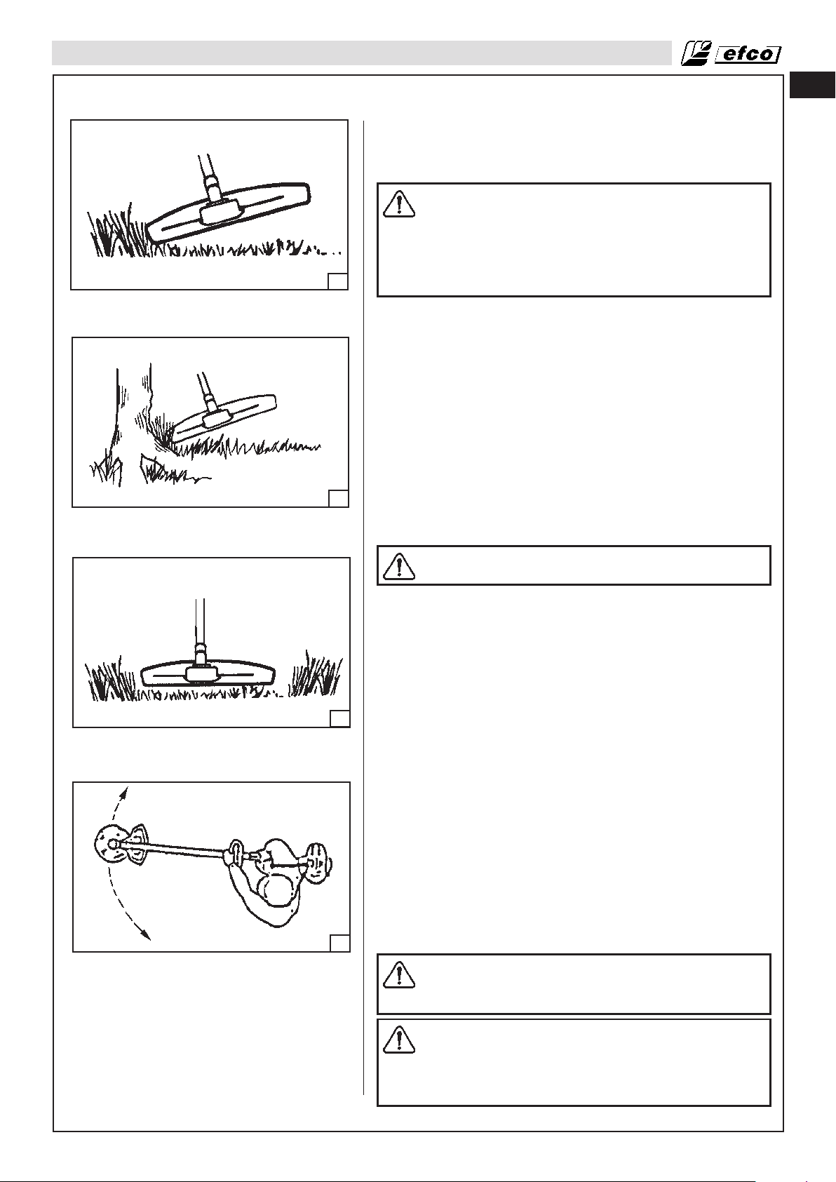
FONCTIONNEMENT
• Arrêtez le moteur, détachez le harnais et posez la machine sur
le sol avant de procéder au ramassage de l'herbe coupée.
Coupe d'herbe à l'aide d'une tête à fils
ATTENTION : la longueur du fil de coupe ne doit pas
excéder le diamètre de coupe prévu. Une fois la
protection appropriée montée, le dispositif de coupe
règlera automatiquement le fil à la longueur
appropriée. L'utilisation d'un fil trop long peut
entraîner la surcharge du moteur et endommager le
52
Coupe avec une tête à fils
• Maintenez la tête de coupe à fils juste au-dessus du sol, à
• Le fil permet de couper l'herbe et les mauvaises herbes qui
• Pour éviter d'endommager les plantes, raccourcissez le fil jus-
mécanisme d'embrayage, ainsi que les pièces à
proximité.
partir d'un angle. L'extrémité du fil effectue tout le travail de
coupe. Laissez le fil travailler à son rythme. N'appuyez jamais
le fil dans la zone de coupe. (Fig.52)
poussent au bord des murs, des clôtures, des arbres et des
bordures. Toutefois, il peut également endommager l'écorce
des arbres et les buissons ou encore les montants de clôtures.
qu'à 10 à 12 cm (4-4.7 in) et réduisez le régime du moteur.
fr
53
54
55
Désherbage
• Le désherbage permet d'éliminer toute la végétation et les
mauvaises herbes indésirables. Maintenez la tête de coupe à
fils juste au-dessus du sol, en l'inclinant légèrement. Passez
l'extrémité du fil autour des arbres, des piliers, des statues et
autres. (Fig.53)
MISE EN GARDE : cette technique de coupe
augmente l'usure du fil.
• Le fil s'abîme plus vite et doit être changé plus souvent si la
coupe s'effectue autour de roches, de briques, de ciment, de
clôtures métalliques, etc., que lorsqu'elle s'effectue autour
d'arbres ou de clôtures en bois.
• Pour ces travaux, n'utilisez pas l'étranglement maximum
comme cela le fil durera plus longtemps et l'usure de la tête de
coupe à fils sera moins importante.
Coupe
• La tête de coupe à fils est idéale pour couper l'herbe difficile
d'accès avec une tondeuse à gazon. Le fil doit être parallèle au
sol lors de la coupe. Évitez d'appuyer la tête de coupe à fils
contre le sol car cela risque d'endommager le fil de nylon et
l'outil de coupe. (Fig.54)
• Évitez que la tête de coupe ne soit en contact permanent avec
le sol pendant les travaux de coupe normaux. Les contacts de
ce type peuvent endommager la tête de coupe et contribuer à
une usure plus rapide de celle-ci.
Balayage
• L'effet de ventilateur du fil en mouvement peut être utilisé pour
un balayage rapide et simple. Pour cela, le fil doit être parallèle
au sol et maintenu au-dessus de la zone à balayer, un
mouvement d'avant en arrière devant être appliqué à la
machine. (Fig.55)
• Pour les travaux de coupe et de balayage, utilisez
l'étranglement maximum afin d'obtenir de meilleurs résultats.
AVERTISSEMENT : n'effectuez jamais à un travail de
coupe par faible visibilité ou par températures
extrêmement élevées ou basses, ou par grandes
gelées.
AVERTISSEMENT : si l'outil de coupe ou le déflecteur
s'encrasse ou s'embourbe, arrêtez toujours le
moteur et assurez-vous que l'outil de coupe est à
l'arrêt avant de procéder au nettoyage. Il convient de
retirer l'herbe, les brindilles, etc. qui peuvent rester
collées sur l'outil de coupe à intervalle régulier.
55
Page 56

fr
ENTRETIEN
Tableau d'entretien
Veuillez noter que les intervalles d'entretien suivant s'appliquent exclusivement à une utilisation en conditions
normales. Si vos travaux de coupe quotidien requièrent une durée d'utilisation plus longue que la normale ou si
les conditions de coupe sont difficiles, raccourcissez en conséquence les intervalles suggérés.
Intégralité de la débroussailleuse Inspection (fuites, craquelures et niveau d'usure) x
Nettoyage quotidiennement après le travail
Commandes (Interrupteur d'allumage, levier d'étrangleur,
gâchette des gaz, gâchette de blocage des gaz)
Réservoir carburant et conduites carburant
Filtre du carburant
Outils de coupe
Pignon conique
Tambour d'embrayage (2)
Protection des outils de coupe
Pare-étincelles (au niveau du silencieux)
Toute la visserie accessible (sauf vis de réglage)
Filtre à air
Ailettes de cylindre
Prises d'air du système de démarrage
Corde de lanceur
Carburateur
Bougie
Amortisseurs de vibrations
Écrou et vis des outils de coupe
Écrou et vis des outils de coupe
Huile moteur (1)
Jeu aux soupapes (2) Vérifier - régler
Chambre de combustion Nettoyer
Tuyaux de carburant Vérifier
Contrôle du fonctionnement
Inspection (fuites, craquelures et niveau d'usure)
Nettoyage
Inspection
Nettoyage, remplacement de la cartouche filtrante (2)
Inspection (dégâts, affûtage et niveau d'usure)
Contrôle de la tension
Affûtage
Inspection (dégâts, usure et niveau de lubrification)
Inspection (dégâts et niveau d'usure)
Remplacement
Inspection (dégâts et niveau d'usure)
Remplacement
Inspection (dégâts et niveau d'usure)
Nettoyage ou remplacement
Inspection
Resserrage
Nettoyage
Remplacement
Nettoyage
Nettoyage quotidiennement après le travail
Inspection (dégâts, affûtage et niveau d'usure)
Remplacement
Contrôle du ralenti (l'outil de coupe ne doit pas
tourner au régime de ralenti)
Contrôle de l'écartement entre les électrodes
Remplacement
Inspection (dégâts et niveau d'usure)
Remplacement par le distributeur
Contrôle visant à s'assurer que l'écrou de verrouillage
de l'outil de coupe est correctement serré
Vérification du serrage des écrous et des vis
Vérifier le niveau
Renouveler
VérifierTuyaux d’huile
utilisation
Avant chaque
x
x
x
x
x
x
x
x
x
x
x
x
x
x
x
x
x
x
x
x
x
x
Tous les 2 ans (Remplacer si nécessaire) (2)
Tous les 2 ans (Remplacer si nécessaire) (2)
ou défectueuse
Si endommagée
Une fois par mois
x
x
x
x
x
x
x
x
x
x
x
x
x
x
Après toutes les 300 h (2)
50h
Selon besoins
Tous les 6 mois ou
x
x
100h
Tous les ans ou
x
x
x
x
x
x
(1) Après le premier mois, renouveler l’huile moteur.
(2) L’entretien de ces éléments doit être confié à un revendeur, à moins d’être qualifié en mécanique et de posséder les outils nécessaires.
FRÉQUENCE D’ENTRETIEN PÉRIODIQUE : Dans le cadre d’une utilisation commerciale, noter les heures de fonctionnement afin de pouvoir établir la fréquence de l’entretien.
56
Page 57

ENTRETIEN
Entretien des outils de coupe
56
Règles générales
• Utilisez exclusivement les outils de coupe avec les protections
• Les dents de la lame doivent être correctement affûtées !
• Respectez la cote sur les lames de scie ! Suivez nos
57
• Assurez-vous que l'outil de coupe n'est ni endommagé ni
• Affûtez régulièrement la lame, en veillant à éliminer aussi peu
fr
AVERTISSEMENT : le respect des angles et des
dimensions spécifiés ci-dessous est absolument
essentiel. Le mauvais affûtage de la lame augmente
le risque de rebond de la débroussailleuse, ainsi que
le risque de projections, ce qui peut entraîner des
blessures corporelles.
Le fait de ne pas remplacer ou réparer un outil de
coupe endommagé peut entraîner des blessures
graves.
La lame est un outil très affûté, il convient donc de
toujours porter des gants de protection avant toute
intervention.
recommandées ! Reportez-vous à la section Outils de
coupe recommandés (Page 41).
Suivez nos instructions et respectez les gabarits d'affûtage
recommandés. Une lame mal affûtée ou endommagée
augmente le risque d'accident. (Fig.56)
instructions. Le réglage incorrect des lames de scie peut
contribuer à augmenter le risque de blocage de la lame et
l'effet de rebond et à endommager celle-ci.
fissuré. Un outil de coupe endommagé doit systématiquement
être remplacé. (Fig.57)
de matière que possible (deux ou trois coups d'affûtage sont
généralement suffisants).
Pour éviter un balourd :
• Affûtez les dents uniformément, sans altérer le contour
proprement dit de la lame.
• Après 5 affûtages, faites contrôler la lame par votre distributeur.
AVERTISSEMENT : ne tentez jamais de réparer un
outil de coupe endommagé en soudant, redressant
ou modifiant sa forme de quelque façon que ce soit.
Cela pourrait contribuer au délogement de l'outil de
coupe et provoquer des blessures graves, voire
mortelles.
Affûtage des coupe-herbe et des lames pour herbe
• Reportez-vous à l'emballage de l'outil de coupe pour des
instructions d'affûtage précises. Affûtez les lames et les dents
de lame à l'aide d'une lime plate à section simple.
• Affûtez tous les bords de façon uniforme pour préserver
l'équilibre de la lame (Fig.56).
AVERTISSEMENT : débarrassez-vous
systématiquement des lames pliées, tordues,
fissurées, cassées ou endommagées de quelque
autre façon. Ne tentez jamais de redresser une lame
tordue pour la réutiliser. Utilisez exclusivement des
lames d'origine, du type spécifié.
Tête de coupe à fils
MISE EN GARDE : assurez-vous toujours que le fil
est correctement enroulé autour du tambour, sous
peine de voir la machine générer des vibrations
parfois douloureuses.
• Utilisez exclusivement les têtes de coupe à fils et les fils
recommandés. Ceux-ci ont été testés par le fabricant pour une
taille de moteur spécifique. Cette précaution est
57
Page 58

fr
ENTRETIEN
• Les machines de petite taille requièrent généralement de
• La longueur du fil est également un élément important de la
58
59
• Assurez-vous que le couteau sur la protection de la tête de
• Pour augmenter la durée de vie du fil de coupe, vous pouvez le
• Utilisez uniquement un fil de même diamètre que le fil d'origine
• Pour allonger le fil pendant la coupe, tapez légèrement la tête
particulièrement importante si vous utilisez une tête de coupe
à fils automatique. Utilisez exclusivement les outils de coupe
recommandés. Reportez-vous à la section Outils de coupe
recommandés (Page 41).
petites têtes de coupe et inversement. Cela s'explique du fait
que pour une coupe utilisant un outil de coupe à fil, le moteur
doit appliquer un mouvement radial au fil en partant de la tête
de coupe et passer outre la résistance de l'herbe à couper.
coupe. L'utilisation d'un fil long exige une plus grande
puissance moteur qu'un fil plus court de même diamètre.
coupe est intacte. Celle-ci permet de couper le fil à la longueur
appropriée.
plonger dans de l'eau pendant quelques jours. Cela
augmentera sa résistance et donc, la durée de son utilisation.
pour éviter toute surcharge du moteur (Fig.58).
de coupe sur le sol (Fig.59). REMARQUE : ne tapez jamais la
tête nylon contre des matières dures, comme du ciment ou des
pierres, car cela peut s'avérer dangereux.
60
61
Remplacement du fil en nylon
1. Appuyez sur la languette (Fig.60) et enlevez le couvercle et la
bobine interne.
2. Pliez le fil en deux, en laissant une partie plus longue d'environ
14 cm (5.5 in) par rapport à l'autre. Bloquez le fil dans l'entaille
spéciale (A, Fig.61). Enroulez le fil dans le sens de la flèche,
en maintenant chaque fil dans son logement, uniformément et
sans les croiser.
3. Après avoir enroulé le fil, bloquez-le dans les fentes spéciales
(Fig.62A) Montez le ressort. Introduisez le fil à travers l'oeillet
(Fig.62B) et tirez-le vers l'extérieur. Bloquez la tête avec le
couvercle.
58
62B62A
Page 59

ENTRETIEN
Réglage du carburateur
Avant de procéder au réglage du carburateur, nettoyez les ouïes
d'aération du couvercle comme indiqué à la Fig.63, ainsi que le
filtre à air comme indiqué à la Fig.64. Reportez-vous aux sections
Fonctionnement - Démarrage de la machine et Entretien - Filtre à
air pour de plus amples détails. Laissez chauffer le moteur avant
de procéder au réglage du carburateur.
Ce moteur est conçu et fabriqué conformément aux
réglementations de Phase 2 de l'EPA (Agence de protection de
l'environnement). Le carburateur est réglé en usine et ne nécessite normalement aucun réglage. Ce modèle de carburateur ne
63
64
permet que le réglage de la vis “T”(Fig.65).
Réglage du ralenti
• Si le moteur démarre, tourne et accélère mais ne tient pas le
• Si l'outil de coupe tourne au ralenti, tournez la vis de réglage
fr
AVERTISSEMENT : ne modifiez en aucune façon le
carburateur, car cela pourrait affecter la conformité
du moteur aux réglementations en matière
d'émissions.
ralenti, tournez la vis de réglage du ralenti “T” dans le sens des
aiguilles d'une montre pour augmenter le ralenti (Fig.65).
du ralenti “T” dans le sens contraire des aiguilles d'une montre
pour réduire le régime du ralenti et arrêter le mouvement de
l'outil de coupe. Si l'outil de coupe continue de tourner au
ralenti, contactez un réparateur afin de procéder au réglage et
n'utilisez pas la machine jusqu'à sa réparation.
65
66
Filtre du carburant
Contrôlez le filtre à carburant (Fig.66) périodiquement.
Remplacez-le s'il est contaminé ou endommagé.
Filtre à air
AVERTISSEMENT : ne nettoyez pas le filtre à air à
l'essence ou avec tout autre produit inflammable afin
d'éviter tout risque d'incendie ou de générer des
vapeurs nocives.
En cas de perte de puissance, vérifiez le filtre à air. Placer le levier
de starter (A, Fig.67) sur la position CLOSED (en haut).
Ôter le couvercle du filtre à air (B) en décrochant la languette
supérieure (C) et les deux languettes inférieures (D).
Vérifiez l'état du filtre (E) quotidiennement ; remplacez-le s'il est
sale ou endommagé. Remettez le filtre en place. Laver l’élément
filtrant dans un solvant non inflammable ou à point d’éclair élevé
et le sécher complètement. Tremper l’élément dans de l’huile
moteur propre et éliminer l’huile en excès. Reposer le couvercle
du filtre à air (B) en introduisant les languettes inférieures (D),
puis la languette supérieure (C).
Un filtre à air usagé ne peut jamais être complètement nettoyé. Il
est recommandé de remplacer le filtre à air par un neuf après un
ans ou 100 h d'utilisation.
Vérifiez que le couvercle et le support du filtre à air sont propre
avant de mettre en place le nouveau filtre.
67
MISE EN GARDE : ne faites jamais tourner le moteur
sans le filtre à air au risque de l'endommager.
Vérifiez que le filtre à air est correctement logé dans
le couvercle de filtre à air avant procéder au
remontage de l'ensemble.
Remplacez toujours un filtre à air endommagé.
Ne nettoyez pas le filtre à l'aide d'une brosse.
59
Page 60

fr
ENTRETIEN
Démarreur
Moteur
Nettoyez périodiquement les ailettes du moteur à l'air comprimé
ou à l'aide d'une brosse (Fig.68). Les impuretés incrustées sur le
68
cylindre peuvent entraîner une surchauffe dangereuse du moteur.
Bougie
Ce moteur utilise une bougie NBK CMR5H avec un espacement
entre les électrodes de 0.6-0.7 mm (0.024-0.028 in) (Fig.69).
69
Remplacez-la par une bougie identique tous les six mois ou plus
fréquemment si nécessaire.
AVERTISSEMENT : le ressort à enroulement est sous
tension et peut "sauter" à tout moment, entraînant de
graves blessures. Ne tentez jamais de le démonter
ou de le modifier.
AVERTISSEMENT : ne faites jamais fonctionner la
débroussailleuse si toutes les pièces ne sont pas
correctement montées, notamment le carter du
démarreur.
Dans la mesure où les pièces peuvent se casser et
voler en éclat, faites réparer le volant-moteur et
l'embrayage à un réparateur agréé.
70
71
AVERTISSEMENT : ne testez jamais le système
d'allumage alors que le connecteur du câble d'allumage est débranché de la bougie ou si la bougie
n'est pas montée dans son logement, au risque de
produire un jaillissement d'étincelles non contrôlé
qui peut entraîner un risque d'incendie. Une
mauvaise connexion entre la borne de la bougie et le
connecteur du câble d'allumage au niveau de la
coiffe peut générer un arc électrique susceptible
d'enflammer les vapeurs de carburant à l'origine d'un
incendie.
Utilisez exclusivement des bougies antiparasites de la gamme
préconisée.
Les facteurs tels que :
- un filtre à air encrassé ;
- des conditions de fonctionnement défavorables, notamment le
fonctionnement en charge partielle ;
peuvent entraîner une détérioration rapide de la bougie.
Silencieux pare-étincelles
Votre débroussailleuse est équipée d'un pare-étincelles (Fig.70),
référence S-419 (DS 2600 4S) - S-421 (DS 3600 4S), conformément aux exigences de la norme SAE J335 ; vous pouvez vérifier
la référence de pièce du pare-étincelles sur le silencieux d'échappement.
AVERTISSEMENT : un dispositif pare-étincelles
défectueux ou modifié peut être à l'origine d'un
incendie.
60
Dans des conditions d'utilisation normale, ce dispositif peut
s'encrasser et doit être contrôlé toutes les semaines et nettoyé en
fonction de son état.
Pour procéder au nettoyage :
• Laissez refroidir le silencieux.
• Retirez les deux (2) vis du déflecteur (A).
• Retirez le déflecteur (B, Fig.71) et le pare-étincelles (C).
Page 61

ENTRETIEN
fr
72
73
• Nettoyez et contrôlez l'écran pare-étincelles. Si l'écran
pare-étincelles est endommagé, défectueux ou détérioré,
remplacez-le.
• Remontez les composants dans l'ordre inverse de la dépose et
serrez la vis à un couple de 4,9 Nm.
AVERTISSEMENT : si l'écran pare-étincelles est
endommagé, défectueux ou détérioré, remplacez-le
ou remplacez l'intégralité du silencieux.
Le dispositif pare-étincelles nécessite un entretien et un
nettoyage périodiques et précis, notamment pour ce qui concerne
les points suivants :
- contrôlez périodiquement l'écran pare-étincelles et
remplacez-le s'il est perforé, tordu ou déformé ;
- vérifiez minutieusement si de la poussière, des débris ou toute
substance organique est en contact avec les pièces du
dispositif pare-étincelles ; nettoyez-le souvent à l'aide d'otuils
ou à l'air comprimé.
Si l'écran doit être remplacé, commandez la pièce interne
complète, références H1835020H800 (B, Fig.71).
AVERTISSEMENT : n'utilisez jamais votre
débroussailleuse si le silencieux est endommagé,
déposé ou modifié. Un silencieux mal entretenu
augment le risque d'incendie et de perte auditive.
Pignon conique (Fig.72-DS 2600 4S) (Fig. 73-DS 3600 4S)
Graissez le pignon au moyen du tube approprié et jusqu'au niveau
du bord inférieur de l'orifice d'accès (A). N'utilisez pas plus de 10
grammes (0.02 lb) de graisse.
MISE EN GARDE : n'utilisez pas de pistolet graisseur
pour cette opération. La haute pression pourrait
endommager les roulements et les joints.
Utilisez une graisse de qualité au bisulfure de molybdène.
Protection
AVERTISSEMENT : si l'outil de coupe ou le déflecteur
74
s'encrasse ou s'embourbe, arrêtez toujours le
moteur et assurez-vous que l'outil de coupe est à
l'arrêt avant de procéder au nettoyage. Il convient de
retirer l'herbe, les brindilles, etc. qui peuvent rester
collées sur l'outil de coupe à intervalle régulier.
Remplacez la protection si elle est endommagée.
Renouvellement de l’huile
Vidanger l’huile lorsque le moteur est encore chaud afin d’assurer
une vidange rapide et complète.
1. Vérifier si le bouchon du dispositif de carburant (A, Fig.74) est
serré.
2. Déposer le bouchon du dispositif de remplissage d’huile, et
vidanger l’huile dans le récipient d’huile en inclinant le moteur
vers le goulot de dispositif de remplissage d’huile (B).
3. Refaire le plein avec de l’huile recommandée (voir page 16) et
75
vérifier le niveau d’huile (C, Fig.75).
4. Reposer le bouchon de remplissage d’huile.
Si de l’huile a éclaboussé, veiller à bien essuyer.
Se laver les mains avec de l’eau et du savon après avoir manipulé
de l’huile usée.
NOTE : Mettre l’huile moteur usée au rebut conformément aux
réglementations sur la sauvegarde de l’environnement. Il est conseillé de l’amener dans un bidon fermé à la station essence la
plus proche pour sa régénération. Ne pas la jeter à la poubelle, la
verser au sol ou dans un égout.
61
Page 62

DIAGNOSTIC DES PANNES
fr
Utilisation du tableau de diagnostic des pannes
AVERTISSEMENT : arrêtez toujours la machine et déconnectez la bougie avant de mettre en
application l'un des remèdes préconisés ci-dessous, à l'exception des opérations nécessitant
que la machine tourne.
Si le problème persiste après avoir vérifié toutes les causes possibles indiquées, contactez votre réparateur
agréé. En cas de problème non référencé dans ce tableau, contactez votre réparateur agréé.
PROBLÈME CAUSE POSSIBLE REMÈDE
Le moteur ne démarre pas ou
il tourne pendant quelques
secondes, puis s'arrête.
(Vérifiez que l'interrupteur
d'allumage est sur la
position de démarrage “I”)
Le moteur démarre mais
n'accélère pas correctement :
Le moteur démarre mais ne
fonctionne pas correctement à
régime élevé.
Le moteur n'atteint pas son
régime maximal.
1. Absence d'étincelle
2. Moteur noyé.
1. Il y a des impuretés dans le réservoir
d’essence ou il y a de l’eau dans le
réservoir d’essence ainsi que dans le
carburant.
2. Filtre à air encrassé.
3. Écran pare-étincelles encrassé.
4. Vérifiez le carburateur.
1. Contrôlez la bougie. Déposez le couvercle.
Vérifier que le capuchon de la bougie d’allumage est bien en place. Retirez la bougie du cylindre. Vérifier que la bougie d’allumage n’est pas
défectueuse et que l’écartement des électrodes est correct. (CMR5H).
2. Passez l'interrupteur d'allumage en position
d'arrêt (OFF) et retirez la bougie. Passez le
levier d'étrangleur sur la position de
fonctionnement et actionnez le lanceur 15 à 20
fois. Cela permet d'évacuer l'excès de carburant dans le moteur. Nettoyez et remontez la
bougie. Actionnez le lanceur trois fois en
mettant le levier d'étrangleur en position de
fonctionnement. Si le moteur ne démarre pas,
passez le levier d'étrangleur sur la position de
démarrage et effectuez la procédure de
démarrage normal. Si le moteur ne démarre
toujours pas, répétez la procédure avec une
bougie neuve.
* Contactez un service d'entretien agréé pour le
réglage du carburateur.
* Contactez un service d'entretien agréé pour le
réglage du carburateur.
1. Nettoyer le réservoir de carburant
2. Nettoyez conformément aux instructions
fournies à la section Entretien - Filtre à air.
3. Procédez au nettoyage conformément aux
instructions fournies à la section Entretien Silencieux pare-étincelles.
4. * Contactez un service d'entretien agréé pour
le contrôle du carburateur.
Le moteur chauffe anormalement
Le moteur démarre, tourne et
accélère, mais ne tient pas le
ralenti.
L'outil de coupe ne fonctionne
pas correctement et génère
des vibrations de forte intensité.
Le moteur démarre et tourne,
mais l'outil de coupe n'est pas
entraîné.
AVERTISSEMENT : ne
touchez jamais la lame
lorsque le moteur tourne.
1. L’écartement des électrodes de la bougie d’allumage est incorrect.
2. Le filtre à air est sale.
3. Les ailettes de refroidissement du
moteur sont encrassées
4. Le niveau d’huile est insuffisant
5. La poulie du lanceur est encrassée par
des brins d’herbe, etc.
Le carburateur nécessite un réglage. Tournez la vis de réglage du ralenti “T” dans le
1. Outil de coupe endommagé
2. Outil de coupe mal monté
1. Outil de coupe mal monté
2. Pignon conique endommagé
3. Tambour d'embrayage endommagé
1. Ajuster l’écartement des électrodes ou remplacer la bougie.
2. Nettoyer le filtre à air.
3. Nettoyer les ailettes de refroidissement du
moteur.
4. Ajouter de l’huile pour faire l’appoint.
5. Nettoyer le groupe lanceur.
sens des aiguilles d'une montre pour augmenter le
régime de ralenti. (Si l'outil de coupe tourne au
ralenti, tournez la vis de ralenti “T” dans le sens
inverse des aiguilles d'une montre pour réduire le
régime de ralenti) ; voir la section Fonctionnement
- Réglage du carburateur.
1. Remplacez l'outil de coupe.
2. Remontez soigneusement l'outil de coupe.
1. Voir la section Montage - Montage de l'outil de
coupe.
2. Procédez au remplacement si nécessaire -
Contactez un réparateur agréé.
3. Procédez au remplacement si nécessaire -
Contactez un réparateur agréé.
* Remarque : ce moteur est conforme aux normes de l'EPA (Agence de protection de l'environnement) en matière de
contrôle des émissions polluantes. Si votre machine présente des problèmes spécifiques de performance ne pouvant
être rectifiés en suivant les instructions de la section Diagnostic des pannes, il est recommandé la porter à un service
d'entretien agréé pour réparation.
62
Page 63

DS 2600 4S
MOTEUR :
Cylindrée : 1.5 cu. in (25 cc)
Alésage : 1.4 in (35 mm)
Course : 1.0 in (26 mm)
PERFORMANCES :
Régime de ralenti : 3,100 ± 200 RPM
Pleins gaz (avec lame) : 11,200 RPM
Puissance : 1.0 HP/0.72 kW (7,000 RPM)
CIRCUIT D’ALIMENTATION DE CARBURANT ET D’HUILE: CIRCUIT D’ALIMENTATION DE CARBURANT ET D’HUILE:
Capacité du réservoir de carburant: 18.6 oz. (550 ml) Capacité du réservoir de carburant: 22 oz. (650 ml)
Capacité du réservoir dʼhuile: 2.7 oz. (80 ml) Capacité du réservoir dʼhuile: 3.4 oz. (100 ml)
Carburant: Essence sans plomb Carburant: Essence sans plomb
DS 2600 4S et DS 3600 4S
SYSTÈME D'ALLUMAGE :
Bougie : NGK CMR5H
Écartement des électrodes : 0.024-0.028 in. (0.6-0.7 mm)
AVERTISSEMENT : coupez le moteur et laissez-le refroidir, puis arrimez la machine avant
remisage ou transport dans un véhicule. Remisez la machine et le carburant dans un endroit où
lesvapeurs de carburant ne seront en contact avec aucune source d'étincelles ou de flammes
nues, notamment à proximité de chaudières, de moteurs ou d'interrupteurs électriques, de fours,
etc. Montez toutes les protections fournies avec la machine pour le remisage. Rangez la
machine de telle sorte que les parties tranchantes ne puissent blesser accidentellement toute
personne passant à proximité. Remisez la machine hors de portée des enfants ou de toute autre
personne non habilitée à l'utiliser.
1. Vidangez et nettoyez le réservoir de carburant dans un lieu suffisamment aéré.
2. Vidangez l'intégralité du carburant dans un conteneur approprié au stockage de l'essence. Faites tourner le
moteur jusqu'à ce qu'il s'arrête de lui-même. Cela permet d'évacuer le carburant susceptible de s'éventer et
de laisser un dépôt de vernis et de gomme dans le circuit d'alimentation de carburant.
3. Nettoyez toutes les substances étrangères accumulées sur la débroussailleuse. Maintenez la machine à
distance de tout agent corrosif tels que les engrais de jardin ou les sels de déverglaçage.
4. Respectez la réglementation locale et nationale en matière de stockage et de manipulation de l'essence.
N'utilisez pas le surplus de carburant dans un autre équipement à moteur 4 temps.
MISE EN GARDE : Il est important d'éviter le dépôt de gomme dans les composants du circuit
d'alimentation de carburant tels que le carburateur, le filtre à carburant, la conduite
d'alimentation de carburant ou le réservoir de carburant au cours du remisage. Les carburants
à base d'alcool (appelés essence-alcool ou E10, ou à base d'éthanol ou de méthanol) sont
hydrophiles, ce qui peut entraîner une séparation des composants du carburant et la formation
d'acides au cours du remisage. Les gaz acides peuvent endommager le moteur.
REMISAGE
63
fr
CARACTÉRISTIQUES TECHNIQUES
DS 3600 4S
MOTEUR :
Cylindrée : 2.18 cu. in (35.8 cc)
Alésage : 1.5 in (39 mm)
Course : 1.2 in (30 mm)
PERFORMANCES :
Régime de ralenti : 3,100 ± 200 RPM
Pleins gaz (avec lame) : 10,000 RPM
Puissance : 1.35 HP/1.0 kW (7,000 RPM)
Page 64

Page 65

INTRODUCCIÓN
Para utilizar correctamente la desbrozadora y evitar accidentes, lea primero este
manual atentamente antes de trabajar con ella. Encontrará explicaciones sobre el
funcionamiento de los distintos componentes, además de instrucciones para realizar las
comprobaciones y el mantenimiento necesarios.
Nota: Las ilustraciones y las especificaciones proporcionadas en este manual
pueden variar según los requisitos de cada país, y están sujetas a cambios sin
previo aviso por parte del fabricante.
MANUAL DEL OPERADOR
El manual del operador está destinado a proporcionar protección al usuario. LÉALO.
Guárdelo en un sitio seguro para consultarlo en el futuro. Conozca los procedimientos
necesarios antes de comenzar a montar la unidad. La preparación y el mantenimiento
adecuados juegan un papel fundamental para obtener la máxima seguridad y
es
rendimiento de la desbrozadora.
Póngase en contacto con el concesionario o el distribuidor local si no comprende alguna
de las instrucciones de este manual.
Además de las instrucciones de uso, este manual contiene párrafos que requieren una
especial atención.
Tales párrafos están marcados con los símbolos descritos a continuación:
Advertencia: Si existe riesgo de accidente o lesiones personales o daños graves a la
propiedad.
Precaución: Si existe riesgo de producir daños en la máquina o en sus componentes
individuales.
ADVERTENCIA: Para garantizar el funcionamiento seguro y correcto de la
desbrozadora, este manual del operador deberá conservarse siempre con
la máquina o cerca de ella. No preste ni alquile la desbrozadora sin el
manual de instrucciones.
ADVERTENCIA: Sólo deberán utilizar la desbrozadora las personas que
entiendan este manual.
65
Page 66

es
ÍNDICE
IDENTIFICACIÓN DEL PRODUCTO
Componentes de la desbrozadora . . . . . . . . . . . . . . . . . . . . . . . . . . . . . . . . . . . . . . . . . . . . . . . . 67
SEGURIDAD
Significado de los simbols de seguridad . . . . . . . . . . . . . . . . . . . . . . . . . . . . . . . . . . . . . . . . . . . 68
Requisitos estatales y locales . . . . . . . . . . . . . . . . . . . . . . . . . . . . . . . . . . . . . . . . . . . . . . . . . . . 68
REGLAS DE SEGURIDAD
Precauciones básicas de seguridad . . . . . . . . . . . . . . . . . . . . . . . . . . . . . . . . . . . . . . . . . . . . . . . 70
Manejo del combustible . . . . . . . . . . . . . . . . . . . . . . . . . . . . . . . . . . . . . . . . . . . . . . . . . . . . . . . . 71
Funcionamiento y seguridad . . . . . . . . . . . . . . . . . . . . . . . . . . . . . . . . . . . . . . . . . . . . . . . . . . . . 71
Precauciones contra sacudidas . . . . . . . . . . . . . . . . . . . . . . . . . . . . . . . . . . . . . . . . . . . . . . . . . .72
Mantenimiento del control . . . . . . . . . . . . . . . . . . . . . . . . . . . . . . . . . . . . . . . . . . . . . . . . . . . . . . 72
Funciones de seguridad . . . . . . . . . . . . . . . . . . . . . . . . . . . . . . . . . . . . . . . . . . . . . . . . . . . . . . . . 73
Accesorio de corte recomendado . . . . . . . . . . . . . . . . . . . . . . . . . . . . . . . . . . . . . . . . . . . . . . . . 73
Comprobación del equipo de seguridad . . . . . . . . . . . . . . . . . . . . . . . . . . . . . . . . . . . . . . . . . . . 73
Precauciones para reducir el riesgo de vibraciones . . . . . . . . . . . . . . . . . . . . . . . . . . . . . . . . . . 74
Precauciones de mantenimiento . . . . . . . . . . . . . . . . . . . . . . . . . . . . . . . . . . . . . . . . . . . . . . . . . 74
ENSAMBLAJE
Instalación de la empuñadura de anillo . . . . . . . . . . . . . . . . . . . . . . . . . . . . . . . . . . . . . . . . . . . . 76
Instalación del protector del accesorio de corte . . . . . . . . . . . . . . . . . . . . . . . . . . . . . . . . . . . . . . 76
Montaje del accesorio de corte . . . . . . . . . . . . . . . . . . . . . . . . . . . . . . . . . . . . . . . . . . . . . . . . . . 76
FUNCIONAMIENTO
Alimentación de combustible . . . . . . . . . . . . . . . . . . . . . . . . . . . . . . . . . . . . . . . . . . . . . . . . . . . . 78
Depósito de aceite del motor . . . . . . . . . . . . . . . . . . . . . . . . . . . . . . . . . . . . . . . . . . . . . . . . . . . . 79
Preparación para cortar . . . . . . . . . . . . . . . . . . . . . . . . . . . . . . . . . . . . . . . . . . . . . . . . . . . . . . . . 79
Arranque del motor . . . . . . . . . . . . . . . . . . . . . . . . . . . . . . . . . . . . . . . . . . . . . . . . . . . . . . . . . . . . 81
Operación en altitudes elevadas . . . . . . . . . . . . . . . . . . . . . . . . . . . . . . . . . . . . . . . . . . . . . . . . .82
Rodaje del motor . . . . . . . . . . . . . . . . . . . . . . . . . . . . . . . . . . . . . . . . . . . . . . . . . . . . . . . . . . . . . 82
Parada del motor . . . . . . . . . . . . . . . . . . . . . . . . . . . . . . . . . . . . . . . . . . . . . . . . . . . . . . . . . . . . . 83
Técnicas de trabajo . . . . . . . . . . . . . . . . . . . . . . . . . . . . . . . . . . . . . . . . . . . . . . . . . . . . . . . . . . . . 83
MANTENIMIENTO
Tabla de mantenimiento . . . . . . . . . . . . . . . . . . . . . . . . . . . . . . . . . . . . . . . . . . . . . . . . . . . . . . . . 88
Mantenimiento del accesorio de corte . . . . . . . . . . . . . . . . . . . . . . . . . . . . . . . . . . . . . . . . . . . . . 89
Ajuste del carburador . . . . . . . . . . . . . . . . . . . . . . . . . . . . . . . . . . . . . . . . . . . . . . . . . . . . . . . . . . 91
Filtro de combustible . . . . . . . . . . . . . . . . . . . . . . . . . . . . . . . . . . . . . . . . . . . . . . . . . . . . . . . . . . 91
Filtro de aire . . . . . . . . . . . . . . . . . . . . . . . . . . . . . . . . . . . . . . . . . . . . . . . . . . . . . . . . . . . . . . . . . 91
Unidad de motor de arranque . . . . . . . . . . . . . . . . . . . . . . . . . . . . . . . . . . . . . . . . . . . . . . . . . . .91
Motor . . . . . . . . . . . . . . . . . . . . . . . . . . . . . . . . . . . . . . . . . . . . . . . . . . . . . . . . . . . . . . . . . . . . . . . 92
Bujía . . . . . . . . . . . . . . . . . . . . . . . . . . . . . . . . . . . . . . . . . . . . . . . . . . . . . . . . . . . . . . . . . . . . . . . 92
Amortiguador de supresión de chispas . . . . . . . . . . . . . . . . . . . . . . . . . . . . . . . . . . . . . . . . . . . . 92
Engranaje cónico . . . . . . . . . . . . . . . . . . . . . . . . . . . . . . . . . . . . . . . . . . . . . . . . . . . . . . . . . . . . . 93
Protector . . . . . . . . . . . . . . . . . . . . . . . . . . . . . . . . . . . . . . . . . . . . . . . . . . . . . . . . . . . . . . . . . . . . 93
Cambio de aceite . . . . . . . . . . . . . . . . . . . . . . . . . . . . . . . . . . . . . . . . . . . . . . . . . . . . . . . . . . . . . 93
66
SOLUCIÓN DE PROBLEMAS
Utilización de la tabla de solución de problemas . . . . . . . . . . . . . . . . . . . . . . . . . . . . . . . . . . . . . 94
ALMACENAMIENTO
Almacenamiento de la desbrozadora . . . . . . . . . . . . . . . . . . . . . . . . . . . . . . . . . . . . . . . . . . . . . . 95
DATOS TÉCNICOS
DS 2600 4S . . . . . . . . . . . . . . . . . . . . . . . . . . . . . . . . . . . . . . . . . . . . . . . . . . . . . . . . . . . . . . . . . 95
DS 3600 4S . . . . . . . . . . . . . . . . . . . . . . . . . . . . . . . . . . . . . . . . . . . . . . . . . . . . . . . . . . . . . . . . . 95
Page 67
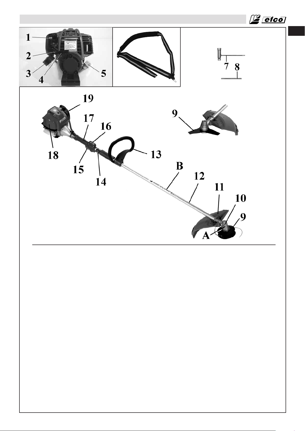
IDENTIFICACIÓN DEL PRODUCTO
6
es
Componentes de la desbrozadora
1 - Palanca de estrangulación
2 - Pera de purga
3 - Tapón del depósito de
combustible
4 - Empuñadura del motor de arranque
5 - Tapón del deposito de aceite
6 - Arnés
7 - Llave de combinación
8 - Pasador de bloqueo
9 - Hoja / Cabezal de recortadora
10 - Engranaje cónico
11 - Protector del accesorio de corte
12 - Barra
13 - Empuñadura de anillo
14 - Punto de enganche del arnés
15 - Activador de aceleración
16 - Interruptor de activación/
desactivación
17 - Bloqueo del activador de
aceleración
18 - Cubierta del filtro de aire
19 - Cubierta del amortiguador
A - Advertencia de seguridad:
Velocidad de rotación de la
herramienta de corte
B - Advertencia de seguridad:
Instrucciones generales
C - Placa de datos
67
Page 68
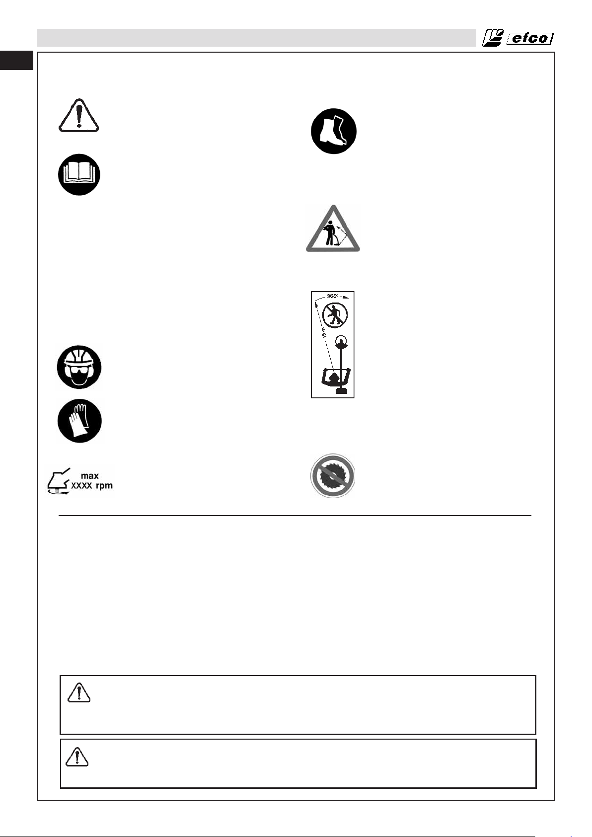
es
SEGURIDAD
Significado de los simbolos de seguridad
- Este símbolo indica Advertencia y
Precaución.
- Este manual contiene mensajes
especiales para llamar la
atención sobre cuestiones de
seguridad y de daños en la
máquina, así como información
útil relativa al funcionamiento y al
mantenimiento. PARA EVITAR
QUE SE PRODUZCAN
LESIONES Y DAÑOS EN LA
MÁQUINA, LEA ATENTAMENTE
TODA LA INFORMACIÓN
PROPORCIONADA.
- Utilice protección para los ojos,
los oídos y la cabeza cuando
emplee este equipo.
- Utilice zapatos o botas de
seguridad resistentes con suelas
antideslizantes y refuerzos
antiperforación.
- Tenga presente que hay objetos
que pueden salir despedidos.
- No permite que nadie se acerque a
menos de 15 metros (50 ft).
- Póngase guantes protectores
antideslizantes y de gran
resistencia cuando manipule la
desbrozadora y las hojas.
- No está permitido utilizar la
- Velocidad máxima en el eje de
salida, rpm
desbrozadora con el disco para
madera.
Requisitos estatales y locales
La desbrozadora está equipada con un amortiguador de limitación de temperatura y una pantalla de
supresión de chispas para cumplir los requisitos de la Práctica Recomendada por SAE J335 y los Códigos
de California 4442 y 4443. Para trabajar en todos los terrenos forestales nacionales y en los terrenos
gestionados por los estados de California, Maine, Washington, Idaho, Minnesota, Nueva Jersey y
Oregón, la ley requiere que los motores de combustión interna estén equipados con una pantalla
de supresión de chispas. Otros estados y agencias federales tienen normas similares en vigor.
Si utiliza una desbrozadoraen un estado o localidad en los que existan tales regulaciones, será legalmente
responsable del mantenimiento del estado de funcionamiento de estos componentes. En caso contrario,
estará infringiendo la ley. El mantenimiento del supresor de chispas se describe en la sección
correspondiente al mantenimiento del amortiguador de supresión de chispas.
Nota: Cuando utilice una desbrozadora para la tala de árboles, consulte el Código de Regulaciones
Federales, Partes 1910 y 1928.
ADVERTENCIA: El sistema de encendido de la unidad genera un campo electromagnético
de muy baja intensidad. Dicho campo puede afectar al funcionamiento de ciertos
marcapasos. Para reducir el riesgo de lesiones graves o mortales, las personas que tengan
un marcapasos deberán consultar a su médico y al fabricante del marcapasos antes de
utilizar esta herramienta.
68
ADVERTENCIA: Mantenga todas las partes del cuerpo alejadas del amortiguador, ya que
sus superficies se encuentran a temperaturas muy altas durante y después de usar la
desbrozadora. Si entra en contacto con el amortiguador, pueden producirse quemaduras
graves.
Page 69
SEGURIDAD
ADVERTENCIA: La exposición a vibraciones por el uso prolongado de herramientas
manuales alimentadas con gasolina podría provocar daños en los nervios o en los vasos
sanguíneos de los dedos, las manos y las muñecas de personas propensas a sufrir
problemas de circulación o hinchazones anormales. El uso prolongado en climas fríos se
ha relacionado con daños en los vasos sanguíneos de personas sanas. Si aparecen
síntomas tales como pérdida de sensibilidad, dolor, pérdida de fuerza, cambio en la textura
o color de la piel, o pérdida de sensibilidad en dedos, manos o muñecas, deje de utilizar
esta herramienta y acuda a un médico.
ADVERTENCIA: Los gases de escape del motor de este producto contienen sustancias
químicas que, según el Estado de California, provocan cáncer, defectos de nacimiento u
otros trastornos genéticos. Utilice la desbrozadora únicamente al aire libre, en zonas con
buena ventilación.
ADVERTENCIA: El diseño de la máquina no podrá modificarse bajo ningún concepto.
Utilice siempre accesorios originales. Las modificaciones y el uso de accesorios no
autorizados pueden causar lesiones graves o mortales al operador u otras personas. Es
posible que la garantía no cubra daños ni responda por el uso de repuestos o accesorios
no autorizados.
es
ADVERTENCIA: Una desmalezadora, desbrozadora o recortadora puede resultar peligrosa
y causar lesiones graves o mortales al operador u otras personas si se utiliza de forma
incorrecta o descuidada. Es extremadamente importante leer y entender el contenido de
este manual.
69
Page 70
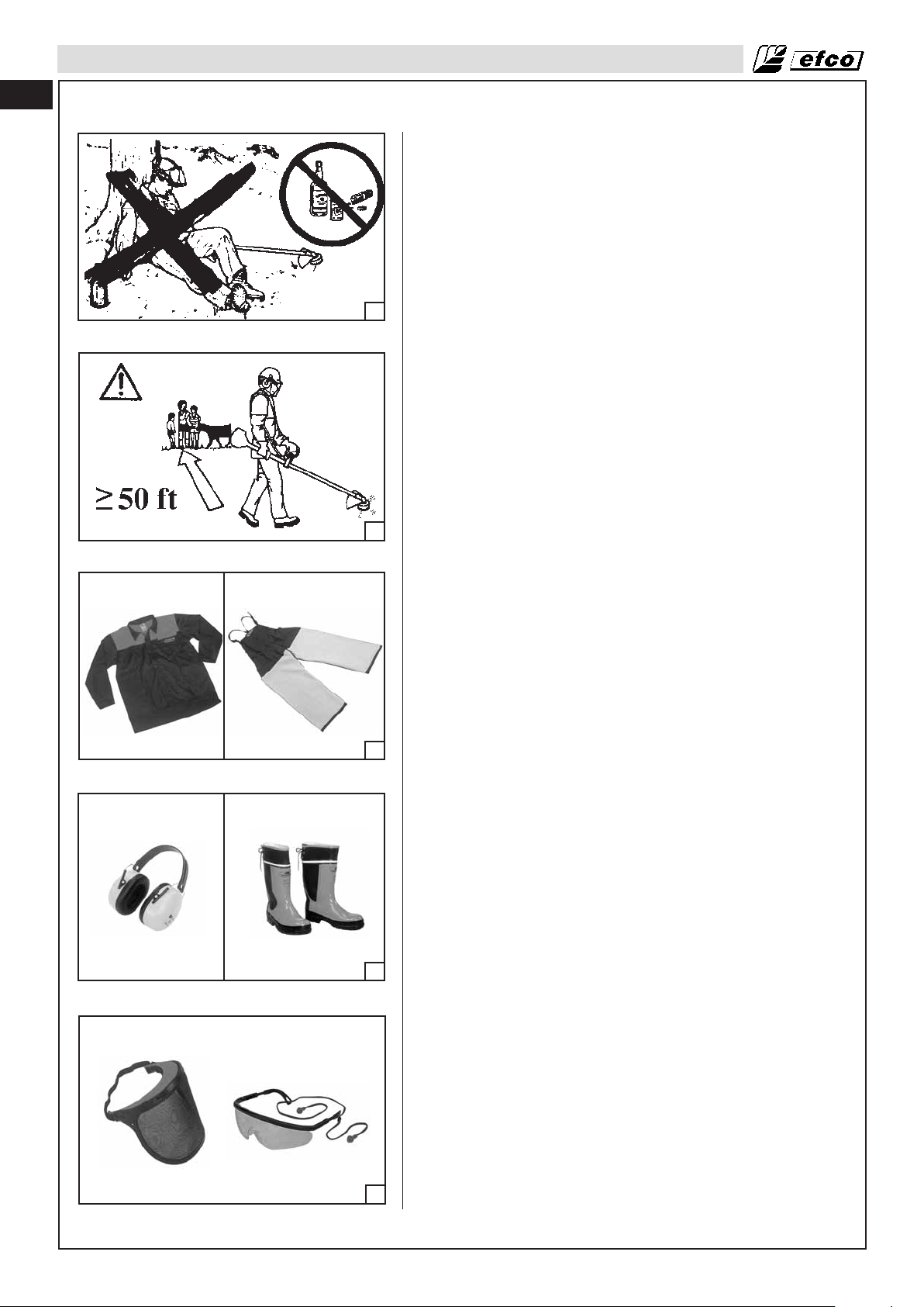
es
REGLAS DE SEGURIDAD
Precauciones básicas de seguridad
• Antes de utilizar la unidad, lea este manual atentamente hasta
que comprenda por completo todas las reglas de seguridad,
precauciones e instrucciones de manejo y sepa cómo
seguirlas.
• La desbrozadora es para uso exclusivo de adultos que
comprendan y puedan seguir las reglas de seguridad,
precauciones e instrucciones de manejo indicadas en este
manual. Nunca se debe permitir que los menores utilicen una
desbrozadora.
• No maneje ni utilice una desbrozadora si está cansado,
1
2
3
4
5
enfermo o indispuesto. Tampoco la utilice si ha tomado alcohol,
drogas o medicamentos. Debe encontrarse en buen estado
físico y con la mente despierta. Trabajar con una
desbrozadora es agotador. Si tiene algún problema que se
pueda agravar a causa de este tipo de trabajo, consulte a su
médico antes de utilizar la desbrozadora (Fig.1). Preste más
atención antes de las pausas para descansar y hacia el final
del turno de trabajo.
• Los niños, transeúntes y animales deben mantenerse a una
distancia mínima de 15 metros (50 pies) del lugar de trabajo.
No permita que se acerquen a la desbrozadora personas ni
animales cuando la arranque o la utilice (Fig.2).
• Los accidentes más importantes relacionados con las
desbrozadoras se producen cuando la hoja o los objetos que
salen despedidos golpean al operador. Mientras trabaje con la
desbrozadora, utilice siempre prendas protectoras de
seguridad homologadas. El uso de prendas protectoras no
elimina el riesgo de lesiones, pero reduce sus efectos en caso
de accidente. Consulte a su proveedor a la hora de elegir
equipos conformes con la legislación. Las prendas deben ser
las adecuadas y no ser un obstáculo. Utilice prendas
protectoras adherentes. Las chaquetas protectoras (Fig.3) y
los pantalones vaqueros (Fig.3) son perfectos para realizar
este trabajo. No se ponga prendas, pañuelos, corbatas o
pulseras que puedan engancharse en las ramas. Si tiene el
pelo largo, recójaselo y protéjaselo (por ejemplo, con un
pañuelo, gorra, casco, etc.). Utilice botas de seguridad con
suelas antideslizantes y refuerzos antiperforación (Fig.4).
Utilice gafas protectoras o protectores faciales (Fig.5).
Emplee protecciones contra el ruido,, protectores para los
oídos que reduzcan el nivel de ruido (Fig.4) o tapones para
los oídos. Si se utilizan protecciones para los oídos, se
deberá tener mucho más cuidado y prestar más atención, ya
que la percepción de señales sonoras de peligro (gritos,
alarmas, etc.) quedará limitada. Quítese las protecciones de
los oídos en cuanto pare el motor. Utilice guantes que
absorban al máximo las vibraciones (Fig. 6, página 71).
• Permita únicamente utilizar esta desbrozadora a aquellas
personas que hayan leído este manual del operador o que
hayan recibido las instrucciones adecuadas para utilizar la
desbrozadora de forma correcta y segura.
• Compruebe la desbrozadora a diario para asegurarse de que
todos sus dispositivos se encuentran en perfecto estado de
funcionamiento.
• No utilice nunca la desbrozadora si está dañada, si se ha
modificado o si se ha reparado o montado incorrectamente. No
desmonte, dañe ni desactive ninguno de los dispositivos de
seguridad. Utilice únicamente las herramientas de corte que se
indican en la tabla (página 73). Sustituye de inmediato las
herramientas de corte o los dispositivos de seguridad que se
hayan deteriorado, roto o desmontado.
• Planifique previamente y con cuidado el trabajo. No se ponga a
cortar hasta que el área de trabajo esté despejada y el suelo
en el que vaya a trabajar sea seguro. Igualmente, si va a talar
árboles, debe haber planificado un sendero de retirada.
• Sólo personal competente puede realizar trabajos de
mantenimiento en la desbrozadoras, excepto los indicados en
este manual.
• La desbrozadora sólo se debe utilizar para desbrozar y
recortar hierba o desbrozar bosques. No se aconseja cortar
otros tipos de material.
70
Page 71

REGLAS DE SEGURIDAD
• No se recomienda enganchar a la toma de fuerza
herramientas o aplicaciones que no haya especificado el
fabricante.
Manejo del combustible
ADVERTENCIA: La gasolina es un combustible muy
inflamable. Tenga mucho cuidado cuando maneje
mezclas de gasolina o combustible. No fume ni
acerque llamas o fuego al combustible o a la
6
• Para reducir el riesgo de incendios y quemaduras, maneje
• Manejar, guarde y transporte el combustible en un contenedor
7
• Manejar el combustible en el exterior donde no haya chispas ni
• Seleccione un solar, pare el motor y deje que se enfríe antes
• Afloje lentamente el tapón del depósito de combustible para
• Apriete firmemente el tapón del depósito de combustible
• Elimine de la unidad el combustible que se haya derramado y
8
9
• No queme nunca el combustible que se haya derramado.
• No fume mientras maneja combustible o utiliza la
• Guarde el combustible en un lugar fresco, seco y bien
• No coloque nunca la desbrozadora en un lugar donde haya
• Guarde la unidad y el combustible en un lugar donde los
• No quite nunca el tapón del depósito con el motor en
• No utilice nunca combustible para operaciones de limpieza.
• Tenga cuidado para que el combustible no entre en contacto
• No exponga el depósito de combustible a la luz solar directa.
• Mantenga el combustible fuera del alcance de los niños.
desbrozadora (Fig.7).
ADVERTENCIA: El combustible y las emanaciones
de combustible pueden causar lesiones graves por
inhalación o en contacto con la piel. Por este motivo,
es preciso adoptar precauciones para manejar
combustible y asegurarse de que existe una
ventilación adecuada.
ADVERTENCIA: Existe peligro de envenenamiento
por monóxido de carbono.
el combustible con cuidado. Es altamente inflamable.
homologado para gasolina (Fig.8).
llamas.
de volver a cargar combustible.
liberar la presión y evitar que el combustible se escape
alrededor del tapón.
después de cargar el combustible. Si el tapón del depósito no
está correctamente apretado, las vibraciones de la unidad
pueden provocar que el tapón se afloje o se salga y se derrame
combustible.
deje que el combustible restante se evapore. Aléjese 3 metros
(10 pies) del lugar donde ha repostado antes de arrancar el
motor (Fig.9).
desbrozadora.
ventilado.
elementos combustibles, como hojas secas, paja, papel, etc.
vapores del combustible no puedan entrar en contacto con
chispas o llamas de calentadores de agua, motores o
interruptores eléctricos, hornos, etc.
funcionamiento.
con su ropa. Cuando el combustible se impregne en la ropa o
en la piel, cámbiese de ropa y lávese las partes del cuerpo que
hayan entrado en contacto con el combustible con agua y
jabón.
es
10
Funcionamiento y seguridad
ADVERTENCIA: Agarre siempre la desbrozadora con
las dos manos cuando el motor esté en
funcionamiento. Sujete firmemente la desbrozadora
colocando los pulgares y los dedos alrededor de la
empuñadura (Fig.10).
71
Page 72
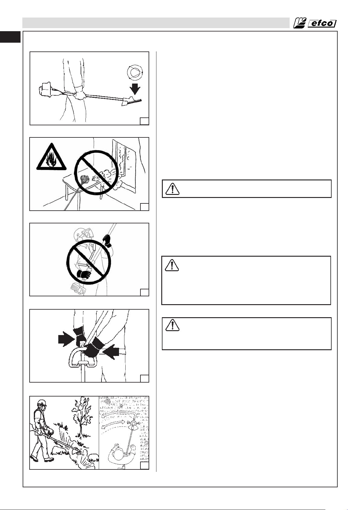
es
REGLAS DE SEGURIDAD
• Mantenga todas las partes del cuerpo alejadas del accesorio
de corte cuando el motor esté en marcha.
• Transporte siempre la desbrozadoracon el motor parado y el
amortiguador alejado del cuerpo. Cuando transporte la
desbrozadora, instale el protector de la hoja (Fig.11). Durante
el transporte en un vehículo, mantenga puesto el protector de
la hoja. Fije correctamente la desbrozadora para evitar que
vuelque, se derrame combustible y sufra daños.
• No utilice la desbrozadora con una sola mano. Si lo hace, el
operador, sus ayudantes, los transeúntes y cualquier otra
persona pueden sufrir lesiones graves. La desbrozadora está
diseñada para utilizarse con las dos manos.
11
• Antes de arrancar el motor, compruebe que el accesorio de
corte no toca ningún objeto.
• Apague el motor antes de dejar la desbrozadora en el suelo.
No deje el motor en marcha sin vigilancia.
• Utilice la desbrozadora únicamente en lugares bien ventilados,
y no la emplee en atmósferas explosivas o inflamables ni en
entornos cerrados (Fig.12). Existe peligro de envenenamiento
por monóxido de carbono.
• No utilice la desbrozadora mientras está subido a una escalera
o a un árbol. Corte siempre desde una posición segura y
estable.
ADVERTENCIA: Tenga mucho cuidado cuando
trabaje en terrenos en pendiente.
12
13
14
• No corte cerca de cables eléctricos.
• Mantenga las empuñaduras secas, limpias y sin mezclas de
combustible o aceite.
• No sitúe la desbrozadora por encima de los hombros para
cortar (Fig.13).
• No utilice nunca la desbrozadora sin el protector de la hoja o el
cabezal.
• No arranque el motor si la barra no está colocada.
Precauciones contra sacudidas
ADVERTENCIA: Las sacudidas pueden producir
lesiones graves. La sacudida es un movimiento
lateral o de avance repentino que se produce cuando
la hoja entra en contacto con algún objeto, como una
rama o un tronco, o cuando la madera se cierra y
aprisiona la hoja de sierra en el corte. Si entra en
contacto con un objeto extraño, se puede perder el
control de la desbrozadora.
Reducción del riesgo de sacudidas
ADVERTENCIA: Tenga en cuenta que pueden
producirse sacudidas. El elemento sorpresa, que
contribuye a que se produzcan accidentes, se puede
evitar cuando se comprende básicamente del motivo
por el que se producen las sacudidas.
• No permita nunca que la hoja entre en contacto con algún
objeto mientras está en movimiento.
• Elimine cualquier obstáculo de la zona de trabajo, como otros
árboles, ramas, rocas, vallas, tocones, etc. Elimine o evite
cualquier obstáculo que la hoja pueda golpear mientras corta.
• Mantenga la hoja afilada. Siga las instrucciones del fabricante
relativas al mantenimiento y afilado de la hoja.
• Empiece y continúe cortando a velocidad máxima. El riesgo de
que se produzcan sacudidas aumenta cuando la hoja se
mueve a menos velocidad.
72
15
Mantenimiento del control (Fig.14-15)
• Mantenga la desbrozadora bien agarrada con ambas manos
cuando el motor esté en marcha, y no la suelte. Una sujeción
firme reducirá las sacudidas y permitirá mantener la
desbrozadora controlada. Mantenga los dedos de la mano
alrededor de la empuñadura.
• Manténgase erguido con el peso del cuerpo distribuido de
manera uniforme sobre ambos pies.
• No eleve la desbrozadora. Podría perder el equilibrio y el
control de la desbrozadora.
Page 73

REGLAS DE SEGURIDAD
Funciones de seguridad
ADVERTENCIA: Como usuario de la desbrozadora, no confíe únicamente en los dispositivos
de seguridad de la herramienta.. Para evitar lesiones graves es preciso tener en cuenta todas
las precauciones de seguridad, las instrucciones y las indicaciones de mantenimiento de este
manual.
ADVERTENCIA: Incluso con un mantenimiento adecuado no es posible garantizar el
correcto funcionamiento de las funciones de seguridad sobre el terreno.
Accesorios de corte recomendados
es
1
2
3
4
5
6
7
8
9A
9B
10A
10B
11A
11B
12A
12B
13
Referencia
4095605
4095597
4175157
63019007B
61172019
4180053
4180052
4180961
4095638R
4095673R
4095674R
4095565R
4095641R
Accesorios de corte
Descripción
Hoja de nailon con 3 dientes, diám. 254 mm (10”)
Hoja de nailon con 4 dientes, diám. 254 mm (10”)
Cabezal “Pro Trim Universal” de 3 hojas, diám. 304, mm (12”)
Cabezal “Tap’n go” con 2 hilos de nailon de 2,7 mm
(.11”), diám. 127 mm (5.1”)
Cabezal “Tap’n go” con 2 hilos de nailon de 2,3 mm
(.094”), diám. 127 mm (5.1”)
Cabezal multihilos universal con 8 hilos (3,3 mm)
(.13”), diám. 69 mm (2.75”)
Cabezal multihilos universal con 6 hilos (3,3 mm)
(.11”), diám. 69 mm (2.75”)
Cabezal multihilos universal con 8 hilos (2,7 mm)
(10”), diám. 132 mm (5.2”)
Hoja de acero con 3 dientes, diám. 254 mm (10”),
grosor 1,2 mm (.05”)
Hoja de acero con 3 dientes, diám. 254 mm (10”),
grosor 1,7 mm (.07”)
Hoja de acero con 3 dientes, diám. 304 mm (10”),
grosor 2,2 mm (.09”)
Hoja de acero con 8 dientes, diám. 254 mm (9”),
grosor 1,2 mm (.05”)
Hoja de acero con 3 dientes, diám. 254 mm (10”),
grosor 2,7 mm (.11”)
Referencia
61170127
4174273A
4174273A
4174273A
61170127
4174273A
61170127
4174273A
61170127
4174273A
61170127
4174273A
61170127
4174273A
61170127
4174273A
4174273A
Protectores
Descripción
Protector de plástico *
Protector de plástico *
Protector de plástico *
Protector de plástico
Protector de plástico
Protector de plástico
Protector de plástico
Protector de plástico
Protector de plástico *
Protector de plástico *
Protector de plástico *
Protector de plástico *
Protector de plástico *
Modelos
DS 2600 4S
DS 3600 4S
DS 3600 4S
DS 3600 4S
DS 2600 4S
DS 3600 4S
DS 2600 4S
DS 3600 4S
DS 2600 4S
DS 3600 4S
DS 2600 4S
DS 3600 4S
DS 2600 4S
DS 3600 4S
DS 2600 4S
DS 3600 4S
DS 3600 4S
*La protección 4174283A no es necesaria.
ADVERTENCIA: El uso de dispositivos de corte no autorizados por el fabricante puede poner
en peligro la seguridad.
ADVERTENCIA: La hoja de sierra no se puede utilizar con la empuñadura de anillo.
73
Page 74

es
REGLAS DE SEGURIDAD
Comprobación del equipo de seguridad
ADVERTENCIA: Nunca utilice una máquina con dispositivos de seguridad defectuosos. Las
operaciones de comprobación y mantenimiento de los dispositivos de seguridad se
describen en esta sección. Si detecta problemas en la máquina durante las comprobaciones,
póngase en contacto con el agente del servicio de reparación.
Palanca de bloqueo de aceleración
La palanca de bloqueo está diseñada para impedir el accionamiento accidental del control de aceleración.
El control de aceleración se bloquea automáticamente en la posición de ralentí.
Cuando suelte la palanca, asegúrese de que el control de aceleración se encuentra bloqueado en la
posición de ralentí.
Presione la palanca y verifique que regresa a la posición de partida después de soltarla.
Compruebe que la palanca y el control de aceleración se mueven sin problemas y que los resortes de
recuperación funcionan bien.
Interruptor de parada
Utilice el interruptor de parada para apagar el motor.
Arranque el motor y asegúrese de que se detiene al ajustar el interruptor en la posición de parada.
Protector del accesorio de corte
Este protector impide que los objetos que están sueltos salgan despedidos en dirección al operador.
Además, evita que el operador pueda tocar accidentalmente el accesorio de corte.
Compruebe que el protector no está deteriorado ni agrietado. Si el protector ha recibido impactos o está
agrietado, sustituyelo.
Utilice siempre el protector recomendado para el accesorio de corte que está usando. Consulte el capítulo
de datos técnicos.
ADVERTENCIA: Nunca utilice un accesorio de corte si no dispone de un protector
homologado. Consulte la sección de datos técnicos.. El empleo de un protector incorrecto o
defectuoso puede ocasionar graves daños personales.
Precauciones para reducir el riesgo de vibraciones
• La desbrozadora está provista de un sistema antivibración (AV) que no se debe modificar ni manipular
bajo ningún concepto.
• Utilice guantes y mantenga las manos calientes.
• Mantenga la hoja afilada y la desbrozadora en buen estado, incluido el sistema AV. Las vibraciones que
se transmiten a las manos aumentan cuando la hoja está desafilada.
• Cuando utilice un accesorio para cabezales de corte con hilo, asegúrese de que el hilo está
perfectamente enrollado. El nivel de vibración aumentará en gran medida si el accesorio está
descompensado.
• Agarre firmemente la unidad en todo momento, pero sin aplicar una presión constante y excesiva sobre
las empuñaduras. Haga pausas con frecuencia. Todas las precauciones indicadas anteriormente no
garantizan que no vaya a sufrir alguna dolencia por vibraciones en las manos o el síndrome de canal
carpiano. Por tanto, los usuarios que utilicen la unidad de forma continua y regular deberán supervisar
atentamente el estado de sus manos y dedos. Si aparece alguno de los síntomas indicados
anteriormente, acuda inmediatamente a un médico.
Precauciones de mantenimiento
ADVERTENCIA: No utilice nunca una desbrozadora que esté dañada, que esté mal ajustada
o que no esté montada por completo y de forma segura.
• Asegúrese de que el accesorio de corte deja de moverse al soltar el activador del control de aceleración.
Si el accesorio de corte funciona al ralentí, es posible que necesite ajustar el carburador. Consulte la
sección dedicada al ajuste del carburador. Si el accesorio de corte sigue funcionando al ralentí después
de ajustar el carburador, póngase en contacto con el concesionario de servicio para solicitar su ajuste y
deje de utilizarlo hasta que esté reparado.
74
ADVERTENCIA: A excepción de lo especificado en las instrucciones de mantenimiento del
manual del operador, la revisión de la desbrozadora deberá estar a cargo de personal de
servicio competente. (Cuando se utilizan herramientas inadecuadas para extraer el volante
o el embrague, o se usa una herramienta incorrecta para sostener el volante a fin de extraer
el embrague, pueden ocasionarse daños estructurales en el volante. Esto podría provocar
que dicho volante reviente y se produzcan lesiones graves.)
Page 75

REGLAS DE SEGURIDAD
• No modifique nunca la desbrozadora de ninguna manera.
• Mantenga las empuñaduras secas, limpias y sin de combustible.
ADVERTENCIA: Utilice solamente los accesorios y repuestos recomendados.
• No toque nunca el accesorio de corte ni intente revisar la desbrozadora con el motor en marcha.
• No utilice nunca combustible para operaciones de limpieza.
• Guarde la desbrozadora en un lugar seco, sin apoyarla en el suelo, con el protector de la hoja instalado
y los depósitos vacíos.
• Cuando la desbrozadora no sirva, tendrá que devolverla al concesionario local para que la desechen de
forma correcta y ecológica.
• Sustituya inmediatamente los dispositivos de seguridad que estén rotos o dañados.
ADVERTENCIA: El amortiguador y otras piezas del motor (por ejemplo, las aletas del
cilindro y la bujía) se calientan durante el funcionamiento y permanecen calientes algún
tiempo después de parar el motor. Para reducir el riesgo de quemaduras, no toque el
amortiguador ni otras piezas mientras estén calientes.
es
75
Page 76

es
ENSAMBLAJE
Instalación de la empuñadura de anillo
Monte la empuñadura en el eje de transmisión y fijela mediante
los tornillos (A, Fig. 16), las arandelas y las tuercas.
La posición de la empuñadura es regulable en función de las
exigencias del operador.
Instalación del protector del accesorio de corte
16
18
Instalación del protector (Fig.18-19)
Fije el protector de la hoja (A) a la barra de unión con los tornillos
(B) en una posición que permita al operador trabajar sin peligro..
NOTA: Cuando utilice cabezales de nailon, monte el protector
de la recortadora (C, Fig.18). Fije el protector de la
recortadora (C) a la protección (A) con los tornillos (D).
ADVERTENCIA: Nunca utilice discos para madera.
ADVERTENCIA: Jamás utilice un accesorio de corte
si no dispone de un protector homologado. Consulte
la sección Accesorios de corte recomendados
(página 73). El uso de un protector incorrecto o
defectuoso puede ocasionar graves daños
personales.
ADVERTENCIA: Es posible que el deflector que
incorpora la desbrozadora no pueda proteger al
operador de todos los objetos extraños (grava,
vidrio, alambre, etc.) que salen despedidos cuando el
accesorio de corte gira. Esos objetos pueden rebotar
y golear al operador.
ADVERTENCIA: Sustituye de inmediato el protector
si está dañado o roto. Nunca intente montarlo en una
posición incorrecta.
Montaje del accesorio de corte
19
20
ADVERTENCIA: Cuando se monta el accesorio de
corte es muy importante asegurarse de que la brida
de transmisión engrana perfectamente en el orificio
central del accesorio. La instalación incorrecta del
accesorio de corte puede ocasionar lesiones graves
o mortales.
ADVERTENCIA: Utilice solamente accesorios de
corte con los protectores recomendados. Consulte la
sección Accesorios de corte recomendados (página
73). Consulte las instrucciones del accesorio de
corte para colocar correctamente el hilo y elegir el
hilo de diámetro adecuado. Mantenga afilados los
dientes de la hoja. Siga nuestras recomendaciones.
Consulte también las instrucciones incluidas en el
paquete de la hoja. Mantenga la hoja correctamente
ajustada. Siga nuestras instrucciones.
76
Page 77

21
ENSAMBLAJE
22
es
ADVERTENCIA: Pare el motor antes de realizar
cualquier operación en el accesorio de corte. El
accesorio sigue girando incluso después de soltar el
control de aceleración. Verifique que el accesorio de
corte está completamente parado y desconecte el
cable de alta tensión de la bujía antes de empezar a
trabajar en él.
ADVERTENCIA: El riego de sacudidas aumenta
cuando se utiliza un accesorio de corte incorrecto o
la hoja está mal afilada.
ADVERTENCIA: Deseche las hojas que estén
dobladas, torcidas, agrietadas, rotas o que presenten
otros defectos (Fig.19, página76). No intente
enderezar una hoja torcida para volver a usarla.
Utilice solamente hojas originales del tipo
especificado.
ADVERTENCIA: Para reducir el riesgo de lesiones
graves, no utilice hilos metálicos o reforzados con
metal u otro material en lugar de hilos de corte de
nailon. El hilo podría romperse en pedazos, que
saldrían despedidos a gran velocidad en dirección al
operador o las personas que se encuentren cerca.
23
Instalación del cabezal de recortadora (Fig.20, pág. 76 - 21)
Coloque la brida superior (A) en su lugar. Presione el botón que
fija el cabezal (B) y apriete el cabezal (C) a mano moviéndolo
hacia la izquierda.
Instalación de la hoja (Fig.22-23)
Gire la tuerca (A) para DS 2600 4S o tornillo (A) para DS 3600 4S
hacia la izquierda para aflojarla. A continuación, quite el anillo
exterior (B) y baje la brida inferior (C). Fije la hoja (D) a la brida
superior (E) y verifique que gira en la dirección correcta. Fije la
brida inferior (C), el anillo exterior (B) y apriete la tuerca (A) para
DS 2600 4S o tornillo (A) para DS 3600 4S hacia la izquierda.
Presione el botón de sujeción (F) para bloquear la hoja y fije la
tuerca (A) aplicando un par de apriete de 25 Nm (18.4 in).
ADVERTENCIA: La flecha que hay en el protector del
accesorio de corte (Fig.24) indica la dirección de
rotación correcta de la herramienta.
ADVERTENCIA: Antes de transportar o guardar la
desbrozadora, instale la protección de la hoja (M),
con referencia 4196086, como se muestra (Fig.25).
24
PRECAUCIÓN: Si no quiere dañar el hilo, no use la
desbrozadora sin el anillo externo (B, Fig.22-23).
25
ADVERTENCIA: No toque ni ajuste nunca la hoja con
el motor en marcha, ya que está muy afilada. Lleve
siempre guantes protectores cuando realice
operaciones de mantenimiento en la hoja.
ADVERTENCIA: El engranaje, cónico puede estar
muy caliente después del uso. Lleve siempre
guantes protectores cuando realice operaciones de
mantenimiento.
77
Page 78

es
FUNCIONAMIENTO
Alimentación de combustible(¡No fume!) (Fig. 28)
Este producto funciona mediante un motor de 4 ciclos. Mezcle
previamente gasolina sin plomo y aceite en un contenedor limpio
homologado para gasolina (Fig.26).
COMBUSTIBLE RECOMENDADO: ESTE MOTOR CUENTA
CON LA CERTIFICACIÓN PARA FUNCIONAR CON GASOLINA
SIN PLOMO DESTINADA A SU USO EN AUTOMOCIÓN CON
UN ÍNDICE DE OCTANO DE 89 ([R + M] / 2) O MÁS (Fig. 27).
Jamás utilice gasolina pasada o sucia ni mezcle a gasolina y
aceite. Evite la entrada de suciedad o agua en el depósito de
26
27
28
29
combustible.
NOTA:
Ciertos factores como la exposición a la luz, la temperatura y el
tiempo afectan a gasolina y causan su deterioro rápido.
En el peor de los casos, el deterioro puede ser inferior a 1 mes.
El uso gasolina sucia puede causar daños graves en el motor
(obstrucciones en el carburador, agarrotamiento de válvulas).
La garantía no cubre los daños causados por combustible en
malas condiciones. Siga estrictamente estas recomendaciones:
• Emplee sólo la gasolina especificada.
• Para evitar el deterioro, mantenga la gasolina en un recipiente
de combustible homologado.
• En caso de almacenamiento prolongado de la máquina (más
de 1 mes), drene el depósito de combustible y el carburador.
GASOLINAS CON ALCOHOL
Si decide utilizar gasolina con alcohol (gasohol), asegúrese que
el octanaje sea al menos tan alto como el recomendado por
Emak. Existen dos tipos de “gasohol”: uno que contiene etano y
otro que contiene metanol. No utilice gasohol con más del 10% de
etano. No utilice tampoco gasolina que contenga metanol (alcohol
metílico o de madera) disolventes ee inhibidores contra la
corrosión. No utilice nunca gasolina con más del 5% de metanol,
incluso cuando ésta contenga di solventes e inhibidores contra la
corrosión.
NOTA:
• La garantía no cubre los daños en el sistema de combustible o
los problemas de rendimiento del motor causados por el uso de
combustibles que contengan alcohol. Emak no puede aprobar
el uso de combustibles con metanol ya que no dispone de
pruebas que demuestren su idoneidad.
• Antes de adquirir combustible en una gasolinera desconocida,
asegúrese de que el combustible no contenga alcohol. Si lo
tuviese, compruebe el tipo y porcentaje de alcohol utilizado. Si
observa algún síntoma de funcionamiento inapropiado porque
la gasolina tiene alcohol, o sospecha que lo tiene, cambie la
gasolina por otra que no contenga alcohol.
78
Llenado del depósito
ADVERTENCIA: Siga las instrucciones de seguridad
relativas al manejo de combustible. Apague siempre
el motor antes de repostar. No añada nunca
combustible a una máquina mientras el motor esté
en marcha o caliente. Aléjese al menos 3 metros (10
pies) del lugar de repostaje antes de arrancar el
motor (Fig.29). ¡NO FUME!
1. Limpie la superficie alrededor del tapón del depósito de
combustible para evitar la contaminación.
2. Afloje lentamente el tapón del depósito de combustible.
3. Vierta con cuidado la mezcla de combustible en el depósito.
Evite que el combustible se derrame.
4. Antes de volver a poner el tapón del depósito, limpie e
inspeccione la junta.
5. Vuelva a poner inmediatamente el tapón del depósito y
apriételo con la mano. Limpie el combustible que se haya
derramado.
Page 79

FUNCIONAMIENTO
NOTA: Es normal que un motor nuevo emita humo durante y
después del primer uso.
ADVERTENCIA: Compruebe la existencia de fugas
de combustible; si detecta alguna, corríjala antes de
utilizar la unidad. Póngase en contacto con un
concesionario de servicio si es necesario.
Depósito de aceite del motor
30
1. Nivel de aceite del motor
PREAUCIÓN:
• Hacer funcionar el motor con aceite insuficiente
puede dañarlo seriamente.
• El motor debe comprobarse siempre estando
parado y sobre una superficie nivelada.
1. Extraiga el tapón de llenado del aceite (A, Fig. 30) y
compruebe el nivel: debe llegar a la parte superior del cuello de
llenado del aceite (B).
2. Si el nivel estuviese bajo, añada el aceite recomendado hasta
alcanzar el cuello del orificio de llenado (C, Fig. 31).
es
31
32
Añada el aceite del motor lentamente para evitar que rebose; la
capacidad del depósito de aceite es reducida.
Cada 10 horas compruebe el nivel de aceite del motor. Si el motor
funciona durante más de 10 horas seguidas, añada aceite hasta
llegar a la parte superior del cuello de llenado.
Utilice aceite Efco para motores de 4 tiempos, o cualquier otro de
alto grado detergente y máxima calidad con certificado de que
cumplea o superae los requisitos de los fabricantes de
automóviles para la clasificación de servicio SG, SF. Los aceites
de motor SG, SF llevan esta designación en el recipiente.
El aceite SAE 10W-30 es el recomendado para usos generales a
cualquier temperatura..
PREAUCIÓN: El uso de un aceite sin detergente o
para motores de 2 tiempos puede llegar a acortar la
vida útil del motor.
El margen de funcionamientooperación recomendado para este
motor es de –5 °C a 40 °C (23 °F a 104 °F).
Preparación para cortar
ADVERTENCIA: Cuando utilice hojas rígidas, no
acerque la desbrozadora a vallas, edificios, troncos
de árboles, piedras u otros objetos que puedan dar
lugar a sacudidas o dañar la hoja. En esos casos se
recomienda utilizar cabezales de corte con hilo de
nailon. Asimismo, esté atento ante la posibilidad de
que aumenten los rebotes.
ADVERTENCIA: La desbrozadora se utiliza
normalmente a ras del suelo con el accesorio de
corte en paralelo al terreno. Si separa la
desbrozadora del suelo o coloca el accesorio de
corte en perpendicular al terreno, puede aumentar el
riesgo de lesiones por dos motivos: el accesorio
queda más expuesto y resulta más difícil controlar la
desbrozadora. Jamás utilice la desbrozadora como
cortasetos.
79
Page 80

es
FUNCIONAMIENTO
ADVERTENCIA: Si la hoja se suelta después de
haberla apretado correctamente, pare de trabajar de
inmediato. Es posible que la tuerca de retención esté
desgastada o dañada y habrá que sustituirla. No
utilice piezas para fijar la hoja que no estén
permitidas. Si la hoja sigue aflojándose, consulte al
concesionario. Nunca utilice la desbrozadora con
una hoja suelta.
Procedimiento de corte básico
1. Utilice guantes antideslizantes para obtener el máximo agarre
33
34
y protección.
ADVERTENCIA: Agarre siempre la desbrozadora con
las dos manos (Fig.33). Asegúrese de mantener el
cuerpo a la izquierda del tubo. No cruce las manos.
Los zurdos deben seguir también estas
instrucciones.
Adopte una postura adecuada para cortar (Fig.34).
2. Mantenga la desbrozadora correctamente agarrada (Fig.33)
mientras el motor esté en marcha. Los dedos deben rodear la
empuñadura y el pulgar debe quedar debajo de ella.
Instalación del arnés
Una correcta regulación del correaje permite un buen equilibrio de
la desbrozadora y una distancia correcta entre el terreno y el
aparato cortante (Fig. 35):
• Utilicese siempre el correaje de tipo sencillo.
• Enganche la desbrozadora al correaje mediante el gancho (A,
35
Fig. 36).
• Ponga el gancho (B, Fig. 36) en la posición adecuada para
obtener el mejor equilibrio de la desbrozadora.
• Ponga la hebilla (C, Fig. 37) en la posición adecuada para la
altura correcta de la desbrozadora.
Equilibrio correcto (Fig.36)
1. Desbrozado forestal
Para equilibrar la máquina, mueva el aro de sustentación hacia
delante o hacia atrás. Aunque este aro esté fijo en algunos
36
modelos, se incluirán una serie de orificios para el gancho de
sustentación. Se considera que la máquina está compensada
cuando cuelga del gancho de sustentación libremente y en
horizontal. Esto reduce el riesgo de golpear piedras cuando es
necesario soltar el manillar.
2. Desbrozado de hierba
Deje que la hoja se equilibre a una altura de corte cómoda, es
decir, cerca del suelo.
80
Precauciones sobre el lugar de trabajo
37
ADVERTENCIA: Corte solamente hierba o maleza.
Para cortar madera, utilice una hoja de sierra
adecuada. No corte metal, plástico, mampostería ni
materiales de construcción que no sean de madera.
Page 81
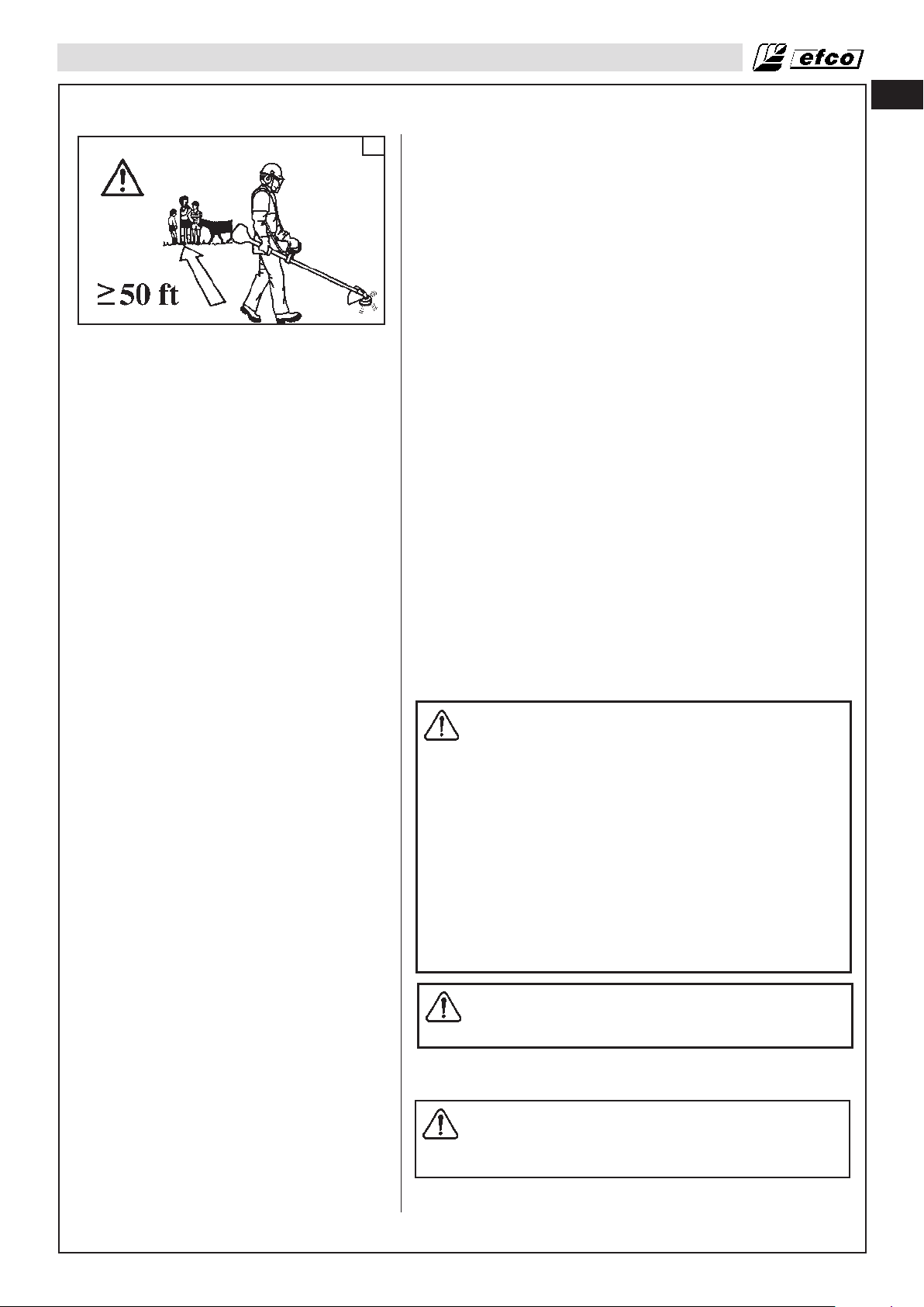
FUNCIONAMIENTO
es
38
• No permita nunca que un niño utilice la desbrozadora. Permita
únicamente utilizar esta desbrozadora a aquellas personas
que hayan leído este manual del operador o que hayan
recibido las instrucciones adecuadas para utilizar la máquina
de forma correcta y segura.
• Haga que ayudantes, transeúntes, niños y animales se
mantengan a una distancia segura del lugar donde realiza el
corte (Fig.38). Durante el desbrozado, los trabajadores deben
mantener una distancia mínima entre ellos de 15 metros (50
pies).
• Corte siempre con los dos pies sobre un terreno firme para no
perder el equilibrio.
• Asegúrese de que puede moverse y mantenerse erguido sin
problemas. Examine el terreno circundante para detectar
obstáculos (raíces, .rocas, ramas, zanjas, etc.) que puedan
dificultar algún movimiento imprevisto. Tenga mucho cuidado
cuando trabaje en terrenos en pendiente.
• No eleve la desbrozadora por encima de la altura del pecho
para cortar. Será más difícil controlarla si se producen
sacudidas.
• No trabaje cerca de cables eléctricos. Deje esta operación a los
profesionales.
• Corte solamente cuando la visibilidad y la iluminación sean las
adecuadas para ver con claridad.
• No corte subido a una escalera; es muy peligroso.
• Si la hoja golpea un objeto extraño, pare la desbrozadora,
examínela y repare los componentes que sea necesario.
• No deje que entre polvo o arena en la hoja. Incluso una
pequeña cantidad de suciedad hará que la hoja se desafile
rápidamente y que aumente el riesgo de sacudidas.
• Pare el motor antes de dejar la desbrozadora en el suelo.
• Esté especialmente atento cuando utilice protección para los
oídos, puesto que tal equipo puede limitar su capacidad para
oír sonidos que indiquen peligro (gritos, señales, advertencias,
etc.).
• Tenga mucho cuidado cuando trabaje en pendientes o en
terrenos desnivelados.
ADVERTENCIA: No utilice hojas rígidas en zonas
pedregosas. Los objetos que salen despedidos o las
hojas dañadas pueden ocasionar lesiones graves o
mortales al operador o los transeúntes. Tenga
cuidados con los objetos que salen despedidos.
Utilice siempre una protección para los ojos
homologada. No se apoye en el protector del
accesorio de corte. Piedras, residuos y otros
materiales pueden saltar a los ojos y causar daños
graves o pérdida de visión. No permita que se acerque
ninguna persona que no esté autorizada. Todo niño,
animal, curioso y ayudante deberá permanecer fuera
de la zona de seguridad de 15 metros (50 pies). Pare
de inmediato la máquina cuando alguien se acerque.
No haga movimientos de vaivén con la máquina sin
antes mirar atrás para asegurarse de que- no hay
nadie en la zona de seguridad.
ADVERTENCIA: No corte nunca si la visibilidad no es
buena, si las temperaturas son muy altas o bajas o a
temperaturas bajo cero.
Arranque del motor
ADVERTENCIA: Cuando se arranca el motor con el
estrangulador en la posición de estrangulación o de
aceleración inicial,, el accesorio de corte empieza a
girar al instante.
• Coloque la desbrozadora en terreno llano y asegúrese de que
no hay objetos ni obstáculos en las proximidades que puedan
entrar en contacto con el accesorio de corte. Mantenga el
81
Page 82

es
FUNCIONAMIENTO
39
40
40
bastidor de la máquina sobre el suelo con la mano izquierda.
(PRECAUCIÓN: No utilice el pie). Consulte la Fig.39.
• Presione lentamente la pera de purga entre 6 y 8 veces (A
Fig.40).
• Tire de la palanca del acelerador (C, Fig. 41) y fíjela en
aceleración media, ponga el interruptor (B) en la posición ;
suelte la palanca (C).
• Ponga la palanca de estrangulación (D, Fig.42) en la posición
de cierre (CLOSE).
• Tire de la cuerda del motor de arranque (Fig.39) hasta que se
oiga el primer encendido del motor (no más de cinco (5)
tirones). Es posible que una unidad nueva requiera más
tirones.
• No se enrolle la cuerda del motor de arranque en la mano.
• Hasta oír las primeras explosiones, mueva gradualmente la
palanca del estrangulador (D, Fig. 43) a la posición OPEN.
• Una vez arrancado, apriete el acelerador (C, Fig. 41) para
desbloquearlo de la posición de semi aceleración media y
déjelo funcionar al mínimo. Caliente el motor hasta que
funcione con suavidad.
• Cuando tire de la cuerda del motor de arranque, no utilice la
longitud total de la cuerda, ya que se puede romper. No deje
que la cuerda del motor de arranque se enrolle rápidamente.
• Agarre la empuñadura y deje que la cuerda vuelva a
enrollarse lentamente.
ADVERTENCIA: El dispositivo de aceleración media
sólo debe utilizarse en la fase de puesta en marcha
del motor en frío.
Para la puesta en marcha del motor en caliente, sitúe el
interruptor (E) hade situarse como en la Fig. 44.
41
42
ADVERTENCIA: No corte material con la palanca de
ralentí rápido/estrangulación en la posición CLOSE.
No ponga la desbrozadora en marcha con el bloqueo
del acelerador de arranque accionado. El operador
no podrá controlar correctamente la desbrozadora
cuando se intente cortar con el bloqueo del
acelerador de arranque accionado.
NOTA - ARRANQUE DEL MOTOR EN CALIENTE:
Siga las instrucciones de arranque indicadas anteriormente,
pero no utilice la posición CLOSE para volver a arrancar la
unidad.
ADVERTENCIA: Las condiciones meteorológicas y la
altitud pueden afectar a la carburación. No permita
que nadie se acerque a la desbrozadora mientras
ajusta el carburador.
Mantenga el motor a aceleración máxima mientras realiza el
corte.
Operación en altitudes elevadas
En zonas muy altas, la mezcla normal de aire y combustible en el
carburador será excesivamente rica, por lo que disminuirá el
rendimiento y aumentará el consumo de combustible.
Para mejorar el rendimiento en estas circunstancias es necesario
realizar modificaciones especíificas en el carburador. Si el motor
funciona siempre en altitudes superiores a 1.500 m (5.000 pies)
sobre el nivel del mar, pida a su concesionario autorizado Efco
que realice estas modificaciones en el carburador.
82
Incluso con un suministro apropiado del carburador, la potencia
del motor se reducirá aproximadamente en un 3,5% por cada 300
m (1.000 pies) de aumento en altitud. El efecto de la altitud en la
potencia del motor será aún mayor si no se modifica el
carburador.
43
Page 83
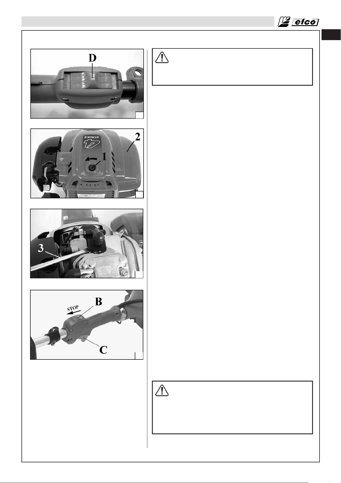
FUNCIONAMIENTO
PREAUCIÓN:
El funcionamiento de la bomba en una altitud inferior
a la que se ajusta el surtidor del carburador puede
reducir el rendimiento del motor, sobrecalentarlo y
ocasionar daños graves causados por el excesivo
paso de mezcla de aire y combustible.
Rodaje del motor
El motor alcanza su potencia máxima tras un período de actividad
de 5 a 8 horas.
44
Durante este período de rodaje, no acelere al máximo la máquina
si no está cortando a fin de evitar tensiones de funcionamiento
excesivas.
Arranque difícil (o arranque de un motor ahogado)
Si el motor no arranca tras 10 tirones, es posible que se haya
ahogado a causa del exceso de combustible. El exceso de
combustible se puede eliminar siguiendo el procedimiento de
arranque del motor en caliente indicado anteriormente.
Asegúrese de que el interruptor ON/STOP se encuentra en la
posición ON. Para arrancar puede que sea necesario tirar varias
veces de la empuñadura de la cuerda del motor de arranque,
dependiendo de cuánto se haya ahogado el motor. Si el motor no
arranca, consulte la TABLA DE SOLUCIÓN DE PROBLEMAS
(página 94).
45
Motor ahogado
• Ajuste el interruptor de activación/desactivación en la posición
STOP.
• Suelte el tornillo de la tapa de la bujía (1, Fig.45).
• Quite la tapa de la bujía (2).
• Acople una herramienta adecuada en la funda de la bujía (3,
Fig. 46).
• Haga palanca para sacar la funda de la bujía.
• Desenrosque la bujía y séquela.
• Abra el acelerador por completo.
• Tire de la cuerda del motor de arranque varias veces para
desahogar la cámara de combustión.
• Vuelva a poner la bujía y conecte su funda; presione
46
firmemente hacia abajo y monte de nuevo las demás piezas.
• Ajuste el interruptor de activación/desactivación en la posición
de arranque I.
• Ponga la palanca de estrangulación en la posición OPEN,
aunque el motor esté frío.
• Ahora, arranque el motor.
es
Parada del motor
Suelte el activador de aceleración (C, Fig.47) y deje que el motor
vuelva al estado de ralentí. Para parar el motor, ponga el
interruptor de activación/desactivación (B) en la posición
“STOP”. No deje la desbrozadora en el suelo si el accesorio de
corte está aún en movimiento.
Si la posición “ STOP ” del interruptor no funciona, lleve la
47
palanca de estrangulación hasta la posición CLOSE (Fig.42) para
detener el motor.
Comprobación previa al funcionamiento
ADVERTENCIA: EL ACCESORIO DE CORTE NUNCA
DEBE GIRAR AL RALENTÍ. Gire el tornillo de
velocidad de ralentí “T” hacia la izquierda para
reducir las RPM de ralentí o póngase en contacto
con el concesionario de servicio para que lo ajuste y
no utilice la unidad hasta que se haya realizado la
reparación.
Cuando el accesorio de corte gira al ralentí se
pueden producir daños personales graves.
El accesorio de corte puede girar al ralentí cuando el embrague
está dañado, con lo que aumenta el riesgo de lesiones por
pérdida de control o por contacto con la herramienta de corte.
83
Page 84

es
FUNCIONAMIENTO
Técnicas de trabajo
Instrucciones generales
ADVERTENCIA:En esta sección se describen las
medidas básicas de seguridad que deben adoptarse
para trabajar con recortadoras y desmalezadoras.
Consulte a un experto en situaciones en las que no
esté seguro de cómo proceder. Póngase en contacto
con el concesionario o el taller. Evite utilizar la
herramienta cuando no se sienta capacitado para
realizar el trabajo. Antes del uso, es preciso entender
las diferencias que existen entre las desbrozadoras
forestales y las desbrozadoras y las recortadoras de
hierba.
Reglas de seguridad básicas
1. Mire siempre alrededor:
• Para asegurarse de que no hay personas, animales u objetos
que puedan impedir el control de la máquina.
• Para asegurarse de que no hay personas, animales y demás
que puedan entrar en contacto con el accesorio de corte o
con los objetos que expele este accesorio.
ADVERTENCIA: No utilice la máquina si no puede
pedir ayuda en caso de accidente.
2. No utilice la máquina si hace mal tiempo, como cuando hay
niebla densa, lluvia intensa, viento fuerte, frío intenso, etc. El
trabajo en estas condiciones es fatigador y conlleva una serie
de riegos añadidos, como la presencia de placas de hielo, el
derribo en dirección imprevista, etc.
3. Asegúrese de que puede moverse y mantenerse erguido sin
problemas. Examine el terreno circundante para detectar
obstáculos (raíces, .rocas, ramas, zanjas, etc.) que puedan
dificultar algún movimiento imprevisto. Tenga mucho cuidado
cuando trabaje en terrenos en pendiente.
4. Apague el motor antes de trasladarse a otra zona.
5. Jamás suelte la máquina con el motor en marcha.
• Utilice siempre el equipo adecuado.
• Asegúrese de que el equipo está bien ajustado.
• Siga las medidas precautorias de seguridad.
• Planifique el trabajo con cuidado.
• Aplique la aceleración máxima cuando empiece a cortar con
la hoja.
• Utilice siempre hojas afiladas.
• Evite las piedras.
ADVERTENCIA: Ni el operador de la máquina ni otras
personas deben intentar quitar el material cortado
mientras el motor está en marcha o cuando el
equipo de corte está girando, ya que pueden
ocasionarse lesiones graves. Pare el motor y el
equipo de corte antes de quitar el material que quede
enrollado en el eje de la hoja, ya que existe el riego
de lesiones. El engranaje cónico puede calentarse
durante el uso y no enfriarse hasta un tiempo
después. Si lo toca puede quemarse.
84
ADVERTENCIA: Tenga cuidados con los objetos que
salen despedidos. Utilice siempre una protección
para los ojos homologada. No se apoye en el
protector del accesorio de corte. Piedras, residuos y
otros materiales pueden saltar a los ojos y causar
daños graves o pérdida de visión. No permita que se
acerque ninguna persona que no esté autorizada.
Todo niño, animal, curioso y ayudante deberá
permanecer fuera de la zona de seguridad de 15
metros (50 pies). Pare de inmediato la máquina
cuando alguien se acerque. No haga movimientos de
vaivén con la máquina sin antes mirar atrás para
asegurarse de que no hay nadie en la zona de
seguridad.
Page 85

FUNCIONAMIENTO
ADVERTENCIA: A veces pueden quedar ramas o
hierba atrapadas entre el protector y el accesorio de
corte. Pare el motor para quitarlas.
Comprobación previa al arranque
• Examine la hoja para asegurarse de que no se han formado
grietas en la base de los dientes o en torno al orificio central.
Si detecta grietas, deseche la hoja (Fig.48).
• Compruebe que la brida de apoyo no se ha agrietado a causa
de la fatiga o de un apriete excesivo. Deseche la brida de apoyo
48
si está agrietada (Fig.49).
• Asegúrese de que la tuerca de seguridad no ha perdido su
capacidad de retención. Esta tuerca debe tener un par de
apriete de 25 Nm (18.4 in) (Fig.49).
• Compruebe que el protector de la hoja no está deteriorado ni
agrietado. Si el protector está agrietado, sustituyelo (Fig.50).
• Compruebe que el cabezal y el protector de la recortadora no
están dañados ni agrietados. Sustituye el cabezal o el
protector si presentan grietas (Fig.50).
ADVERTENCIA: Jamás utilice la máquina sin un
protector o con un protector defectuoso.
es
49
50
ADVERTENCIA: Antes de arrancar la máquina es
preciso instalar la cubierta y el eje del embrague
para que el embrague no se salga y cause lesiones.
Asegúrese de que el accesorio de corte no puede
entrar en contacto con ningún objeto.
Asegúrese de que en la zona de trabajo no haya
personas que no estén autorizadas a las que se
puedan causar lesiones. La distancia de seguridad
es de 15 metros (50 pies).
Métodos de trabajo
ADVERTENCIA: Intente no utilizar el cuarto superior
de la hoja para cortar. Si intenta cortar con esta parte
de la hoja pueden producirse sacudidas debido a la
velocidad de rotación de la hoja.
Desbrozado forestal
• Antes de empezar a trabajar, examine la zona que va a
desbrozar y determine de qué tipo de terreno se trata, cuál es
la pendiente, si hay piedras, si presenta depresiones, etc.
• Empiece por el extremo del terreno que le resulte más fácil y
despeje la zona en la que va a trabajar.
• Trabaje de forma sistemática de lado a lado de la zona que ha
elegido y desbroce entre 4 y 5 metros (13 - 14 pies) en cada
pasada. Esto permite aprovechar el alcance máximo de la
máquina en ambas direcciones y abarcar una extensión de
terreno variada de forma cómoda.
• Desbroce una franja de aproximadamente 75 metros de
longitud (250 pies) y desplace la lata de combustible conforme
avance el trabajo.
• En terrenos en pendiente es conveniente trabajar a lo largo de
la pendiente. Es mucho más sencillo que tener que subir y
bajar.
• Para evitar zanjas y otros obstáculos del terreno, debería saber
en qué zona va a maniobrar. También debería tener en cuenta
la orientación en función del viento para que los troncos
cortados caigan en la zona desbrozada del bosque.
Desbrozado de hierba con una hoja para hierba
• No se deben utilizar hojas y cuchillas para hierba en troncos de
madera.
85
Page 86
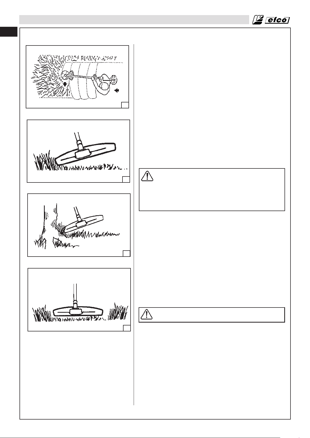
es
FUNCIONAMIENTO
• Las hojas para hierba se pueden utilizar con hierba alta y
gruesa.
• La hierba se corta con un movimiento pendular de derecha a
izquierda y de izquierda a derecha que permite cortar y
regresar a la posición de partida, respectivamente. Realice el
corte con la parte izquierda de la hoja (algo más del cuarto
superior) (Fig.51).
• Si la hoja se desvía hacia la izquierda durante el desbrozado,
la hierba se depositará en línea, lo que facilitará su recogida
con un rastrillo, por ejemplo.
• Intente trabajar a un ritmo constante. Manténgase bien erguido
con los pies separados. Avance después de que la hoja vuelva
51
a la posición de partida y apóyese de nuevo firmemente en el
suelo.
• Deje que la cubierta de apoyo descanse ligeramente sobre el
suelo para impedir que la hoja golpee el suelo.
• Para reducir el riesgo de que el material se enrolle en la hoja,
siga estas instrucciones:
1. Utilice siempre la aceleración máxima para trabajar.
2. Evite el material anteriormente cortado cuando la hoja
regrese a la posición de partida.
• Pare el motor, desenganche el arnés y deposite la máquina en
el suelo antes de empezar a recoger el material cortado.
Recorte de hierba con un cabezal de recortadora
52
53
PRECAUCIÓN: No utilice hilo de segar con más
longitud de la prevista en función del diámetro. La
cuchilla que incorpora la máquina ajustará
automáticamente la longitud del hilo después de
instalar correctamente el protector. El uso de hilo
demasiado largo puede sobrecargar el motor y
producir daños tanto en el mecanismo del embrague
como en las piezas próximas.
Recorte
• Sujete el cabezal de la recortadora en ángulo justo sobre el
nivel del suelo. Es el extremo del hilo el que realiza el trabajo.
Deje que el hilo funcione a su propio ritmo y no haga presión
contra la zona que está cortando (Fig.52).
• El hilo permite eliminar fácilmente la hierba y la maleza
adherida a paredes, vallas, árboles y bordes; sin embargo,
puede dañar la corteza de árboles y arbustos delicados, así
como las estacas de las cercas.
• Si no quiere dañar las plantas, acorte la longitud del hilo a 10
o 12 cm (4 - 4.7 in) y reduzca la velocidad del motor.
Desbrozado
• Con la técnica de desbrozado se elimina la vegetación no
deseada. Mantenga el cabezal sobre el nivel del suelo e
inclínelo. Deje que el extremo del hilo toque el suelo cuando
trabaje alrededor de árboles, estacas, estatuas y similares
(Fig.53).
PRECAUCIÓN: Esta técnica conlleva un mayor
desgaste del hilo.
86
• Cuando se trabaja en zonas donde hay piedras, ladrillos,
54
asfalto, vallas metálicas, etc., el hilo se desgasta con más
rapidez que cuando está en contacto con árboles y vallas de
madera, por lo que es preciso hacer avanzar el hilo con más
frecuencia.
• Durante las operaciones de corte y desbrozado debería
usarse una velocidad de aceleración inferior a la máxima para
que el hilo dure más y el cabezal sufra menos desgaste.
Corte
• La recortadora es perfecta para cortar la hierba a la que
resulta difícil llegar con un cortacésped. Mantenga el hilo en
paralelo al suelo mientras corta. Evite presionar el cabezal de
la recortadora contra el suelo, ya que podría destrozar el
césped y dañar la herramienta (Fig.54).
• No permita que el cabezal entre continuamente en contacto
Page 87

FUNCIONAMIENTO
con el suelo durante las operaciones de corte habituales. De lo
contrario, podría estropearse y desgastarse.
Barrido
• El efecto ventilador que produce la rotación del hilo puede
servir para despejar la zona de forma rápida y sencilla.
Mantenga el hilo en paralelo sobre la zona que desea
despejar y mueva la herramienta de un lado a otro (Fig.55).
• Para obtener resultados óptimos, debería utilizar la aceleración
máxima durante el corte y el barrido.
es
55
ADVERTENCIA: No corte nunca si la visibilidad no es
buena, si las temperaturas son muy altas o bajas o a
temperaturas bajo cero.
ADVERTENCIA: Si la herramienta de corte o el
deflector se obstruyen o atascan, apague el motor y
espere a que la herramienta de corte se pare antes
de limpiarlos. Hay que quitar la hierba, la maleza y
demás de la herramienta de corte de forma
periódica.
87
Page 88

es
MANTENIMIENTO
Tabla de mantenimiento
Tenga en cuenta que los siguientes intervalos de mantenimiento se aplican solamente en condiciones de
funcionamiento normales. Si para su trabajo diario es necesario utilizar la desbrozadora durante más tiempo del
normal, o si las condiciones de corte son duras, los intervalos sugeridos se deberán ajustar en consecuencia.
Toda la máquina Inspeccionar (fugas, grietas y desgaste) x
Limpiar tras finalizar el trabajo diario
Controles (interruptor de encendido, palanca de estrangulación,
activador de aceleración, interbloqueo del activador)
Depósito y tubos de combustible
Filtro de combustible
Accesorios de corte
Engranaje cónico
Tambor del embrague (2)
Protector de los accesorios de corte
Pantalla de supresión de chispas (en el amortiguador)
Todas las tuercas y tornillos accesibles (no los tornillos de
ajuste)
Filtro de aire
Aletas del cilindro
Salidas de ventilación del sistema del motor de arranque
Cuerda del motor de arranque
Carburador
Bujía
Soportes de vibración
Tornillos y tuercas del accesorio de corte
Tornillos y tuercas del accesorio de corte
Aceite de motor (1)
Holgura de válvulas (2) Comprobar-ajustar
Cámera de combustión Limpiar
Tubos de combustible Comprobar
Comprobar el funcionamiento
Inspeccionar (fugas, grietas y desgaste)
Limpiar
Inspeccionar
Limpiar, sustituir el elemento de filtro
Inspeccionar (daños, afilado y desgaste)
Comprobar la tensión
Afilar
Inspeccionar (daños, desgaste y nivel de grasa)
Inspeccionar (daños y desgaste)
Sustituir
Inspeccionar (daños y desgaste)
Sustituir
Inspeccionar (daños y desgaste)
Limpiar o sustituir
Inspeccionar
Volver a apretar
Limpiar
Sustituir
Limpiar
Limpiar tras finalizar el trabajo diario
Inspeccionar (daños y desgaste)
Sustituir
Comprobar el ralentí (el accesorio de corte no
debe girar al ralentí)
Contrôle de l'écartement entre les électrodes
Remplacement
Inspeccionar (daños y desgaste)
Sustituir en el concesionario
Comprobar que la tuerca de seguridad del equipo de
corte está correctamente apretada.
Comprobar que las tuercas y los tornillos están apretados.
Comprobar el nivel
Cambiar
ComprobarTubos de aceite
(2)
defectos
necesario
Cada año
Si hay daños o
x
x
x
x
x
x
x
x
x
Según sea
x
x
x
x
x
Mensualmente
Antes de cada uso
x
x
x
x
x
x
x
x
x
x
x
x
x
x
x
x
x
x
x
x
x
x
Después de cada 300 horas (2)
Cada 2 años (remplace si es necesario) (2)
Cada 2 años (remplace si es necesario) (2)
o 50 horas
x
x
Cada año
o 100 horas
x
x
x
x
x
x
(1) Cambie el aceite del motor después del primer mes de funcionamiento.
(2) El servicio de estos elementos debe realizarlos elsu concesionario, a menos que seusted disponga de las herramientas adecuadas y los conocimientos mecáni-
cos necesarios.
PERÍODO DE SERVICIO REGULAR: Para uso comercial, anote las horas de funcionamiento para determinar los intervalos de mantenimiento apropiados.
88
Page 89
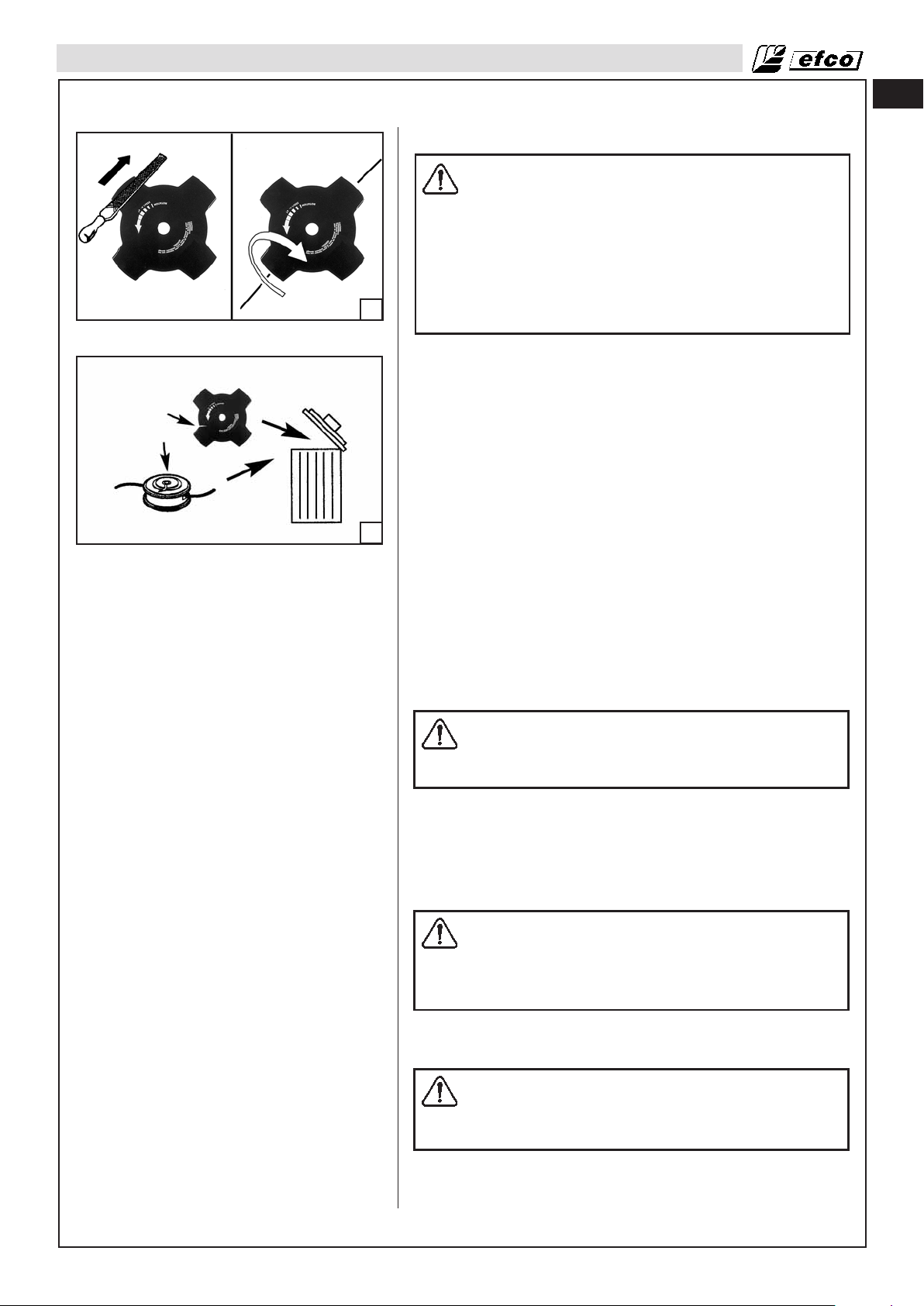
MANTENIMIENTO
Mantenimiento del accesorio de corte
ADVERTENCIA: Es fundamental ajustarse a los
ángulos y dimensiones que se especifican a
continuación. Si la hoja no está bien afilada, existe el
riesgo de que las sacudidas de la desbrozadora
aumenten y que salgan más objetos despedidos que
puedan causar lesiones.
Si el accesorio de corte se daña y no se sustituya o
repara, se pueden producir lesiones graves.
Las hojas están muy afiladas. Lleve siempre guantes
56
57
Reglas generales
• Utilice solamente accesorios de corte con los protectores
• Mantenga afilados los dientes de la hoja. Siga nuestras
• Mantenga la hoja de sierra correctamente ajustada. Siga
• Compruebe si el accesorio de corte está dañado o agrietado.
• Afile la hoja con frecuencia, tratando de limarla lo menos
protectores cuando realice operaciones de
mantenimiento en las hojas.
recomendados. Consulte Accesorios de corte
recomendados (página 73).
instrucciones y utilice el calibrador de limado recomendado. El
riesgo de accidentes aumenta cuando la hoja está mal afilada
o dañada (Fig.56).
nuestras instrucciones. Cuando la hoja de sierra está mal
instalada aumenta el riesgo de que se atasque y sufra daños,
así como de que produzcan sacudidas.
Sustituye siempre los accesorios de corte que estén dañados
(Fig.57).
posible. Basta con pasar dos o tres veces la lima.
es
Para evitar descompensaciones:
• Afile las cuchillas de manera uniforme, sin modificar el
contorno de la hoja original.
• Lleve la hoja al concesionario para que la comprueben
después de afilarla unas 5 veces.
ADVERTENCIA: No suelde, enderece ni modifique la
forma de los accesorios de corte dañados para
repararlos. Algunas partes de la herramienta podrían
separarse y ocasionar lesiones graves o mortales.
Afilado de cuchillas y hojas para hierba
• Consulte las instrucciones de afilado en el paquete del
accesorio de corte. Utilice una lima plana de filo único para
afilar las hojas y las cuchillas.
• Para evitar que la hoja se descompense, afile todas las aristas
por igual (Fig.56).
ADVERTENCIA: Deseche las hojas que estén
dobladas, torcidas, agrietadas, rotas o que presenten
otros defectos. No intente enderezar una hoja torcida
para volver a usarla. Utilice solamente hojas
originales del tipo especificado.
Cabezal de recortadora
PRECAUCIÓN: Asegúrese de que el hilo de la
recortadora está enrollado alrededor del cilindro de
manera firme y uniforme si no quiere que la máquina
genere vibraciones perjudiciales.
• Utilice los cabezales y el tipo de hilo recomendados, que el
fabricante haya especificado como aptos para un motor en
89
Page 90

es
MANTENIMIENTO
particular después de someterlos a pruebas. Esto es
especialmente importante cuando se utilizan cabezales
completamente automáticos. Utilice únicamente el accesorio
de corte recomendado. Consulte Accesorios de corte
recomendados (página 73).
• Las máquinas de menor tamaño suelen requerir cabezales
más pequeños, y viceversa. Esto se debe a que, durante el
desbrozado con hilo, el motor debe proyectar el hilo
radialmente desde el cabezal y vencer la resistencia que
opone la hierba.
• La longitud del hilo también es importante. Un hilo más largo
58
59
necesita más potencia del motor que otro de menos longitud y
mismo diámetro.
• Asegúrese de que la cuchilla del protector de la recortadora
está intacta. Esta cuchilla sirve para cortar la longitud de hilo
correcta.
• Para prolongar la duración del hilo, puede sumergirlo en agua
durante un par de días. De esta manera aumentará su
resistencia y durará más.
• Utilice solamente hilo que tenga el mismo diámetro que el
original si no quiere sobrecargar el motor (Fig.58).
• Para que salga más hilo del cabezal, golpéelo suavemente
contra el suelo mientras trabaja (Fig.59). NOTA: Nunca golpee
el cabezal de nailon contra superficies duras, como asfalto o
piedras, ya que podría ser peligroso.
60
61
Cambio del hilo de nailon
1. Presione la lengüeta (Fig.60) y quite la tapa junto con la
bobina interna.
2. Doble el hilo hacia atrás y deje un extremo 14 cm (5.5 in) más
largo que el otro. Bloquee el hilo en la muesca (A, Fig.61). Con
cada extremo en la ranura correspondiente y sin cruzarlos,
enrolle el hilo en la dirección que indica la flecha.
3. Cuando termine de enrollarlo, enganche el hilo en las
hendiduras (Fig.62A) y monte el resorte. Inserte el hilo por el
orificio pequeño redondo (Fig.62B) y tire del hilo hacia fuera.
Bloquee el cabezal con la tapa.
90
62B62A
Page 91
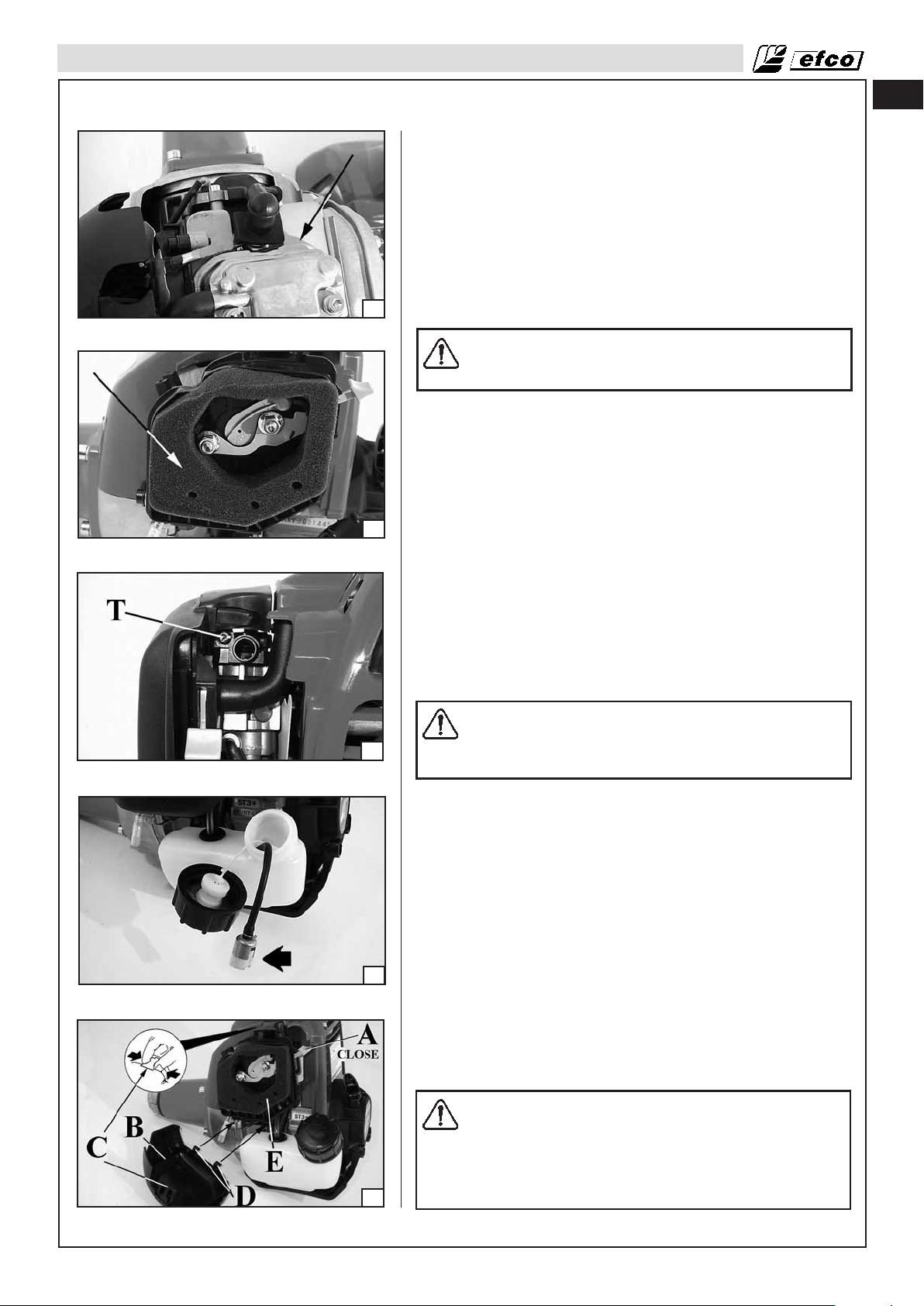
MANTENIMIENTO
Ajuste del carburador
Antes de ajustar el carburador, limpie las salidas de ventilación
como se muestra en la Fig.63, y el filtro de aire como se indica en
la Fig.64. Para obtener más información, consulte las secciones
de funcionamiento de la unidad de arranque y de mantenimiento
del filtro de aire. Deje que el motor se caliente antes de ajustar el
carburador.
Este motor está diseñado y fabricado para cumplir las normas de
Fase 2 de la EPA (Agencia de protección del medio ambiente. El
carburador se ha ajustado en fábrica y no debería requerir ningún
ajuste. En el carburador sólo se puede ajustar el tornillo “T”
63
64
(Fig.65).
ADVERTENCIA: No altere nunca el carburado, ni
siquiera en situaciones en las que el motor no
cumpla las normas de emisiones.
Ajuste de la velocidad de ralentí
• Si el motor arranca, se pone en marcha y acelera pero no se
pone a ralentí, gire el tornillo de velocidad de ralentí “T” hacia
la derecha para aumentar la velocidad de ralentí (Fig. 65).
• Si el accesorio de corte gira al ralentí, gire el tornillo de la
velocidad de ralentí “T” hacia la izquierda para reducir las
RPM de ralentí y detener el movimiento del accesorio. Si el
accesorio de corte sigue funcionando al ralentí, póngase en
contacto con el concesionario de servicio para solicitar su
ajuste y deje de utilizarlo hasta que esté reparado.
es
65
66
Filtro de combustible
Compruebe periódicamente el filtro de combustible (Fig.66).
Sustitúyalo si está contaminado o dañado.
Filtro de aire
ADVERTENCIA: No limpie el filtro con gasolina u
otros disolventes inflamables a fin de evitar que se
cree el peligro de incendio o que se generen
emisiones de evaporación perjudiciales.
Si detecta una reducción de la potencia, compruebe el filtro de
aire. Mueva la palanca del estrangulador (A, Fig. 67) a la posición
CLOSED (hacia arriba).
Extraiga la cubierta del filtro de aire (B) desenganchando la
lengüeta superior (C) de la parte superior de la cubierta del filtro
de aire y las dos lengüetas inferiores (D).
Compruebe el filtro (E) a diario. Cámbielo si está sucio o dañado.
Lavear el elemento en un disolvente que no sea inflamable o con
un punto alto de inflamación y séquelo a fondo. Empape el
elemento en aceite de motor limpio y escurrair el exceso de
aceite. Vuelta a instalar el filtro. Vuelva a instalar la cubierta del
filtro de aire (B) insertando primero las lengüetas inferiores (D), y
luego la lengüeta superior (C).
Un filtro de aire usado nunca se puede limpiar por completo. Se
recomienda sustituir el filtro de aire por otro nuevo tras 1 años o
100 horas de funcionamiento.
Asegúrese de que la cubierta y el soporte están limpios antes de
instalar un filtro nuevo.
67
PRECAUCIÓN: No ponga nunca el motor en marcha
sin el filtro de aire, ya que se pueden producir daños
importantes.
Compruebe que el filtro de aire está correctamente
colocado en su cubierta antes de volver a montarlo.
Sustituya siempre el filtro si está dañado.
No limpie el filtro con un cepillo.
91
Page 92

es
MANTENIMIENTO
Unidad de motor de arranque
ADVERTENCIA: El resorte de la bobina está bajo
tensión y podría salir despedido provocando
lesiones graves. No intente desmontarlo ni alterarlo.
Motor
Limpie periódicamente las aletas del cilindro con aire comprimido
o con un cepillo (Fig.68). Si hay impurezas en el cilindro, es
posible que el motor se recaliente de forma peligrosa.
68
ADVERTENCIA: No ponga nunca la máquina en
marcha sin estar todas las piezas correctamente
colocadas en su sitio, incluido el alojamiento de
arranque.
Puesto que las piezas se pueden romper y salir
despedidas, los trabajos de reparación del volante y
el embrague los debe realizar personal de un
concesionario de servicio con la formación
adecuada.
Bujía
En este motor se utiliza una bujía NBK CMR5H con una
69
separación de las puntas del electrodo de 0.6-0.7 mm (0.024-
0.028 in) (Fig.69). Utilice una bujía de repuesto exactamente igual
a la original y sustitúyala cada seis meses o con mayor
frecuencia, si es necesario.
70
71
ADVERTENCIA: No someta nunca el sistema de
encendido a pruebas con el conector del cable de
encendido desconectado de la bujía o sin estar
correctamente puesta la bujía, ya que las chispas no
contenidas pueden provocar un incendio. Una
conexión floja entre el borne de la bujía y el conector
del cable de encendido en la funda puede dar lugar a
la formación de arco, que puede inflamar los gases
combustibles y provocar un incendio.
Utilice solamente bujías de tipo resistor de gama homologada.
Factores tales como:
- filtro de aire sucio,
- y condiciones de funcionamiento desfavorables (por ejemplo,
funcionamiento con carga parcial)
pueden provocar que la bujía se deteriore rápidamente.
Amortiguador de supresión de chispas
La desbrozadora está equipada con un sistema de supresión de
chispas, con referencia S-419 (DS 2600 4S) - S-421 (DS 3600
4S), (Fig.74) que cumple los requisitos de la norma SAE J335.
Puede consultar la referencia de este sistema en el propio
amortiguador.
ADVERTENCIA: Si la pantalla del sistema de
supresión de chispas es defectuosa o se ha
modificado, puede existir el riesgo de incendio.
92
La pantalla puede ensuciarse con el uso normal, por lo que
deberá inspeccionar semanalmente y limpiarse según sea
necesario.
Para limpiarla:
• Deje que el amortiguador se enfríe.
• Extraiga los dos (2) tornillos del deflector (A).
• Quite el deflector (B, Fig.71) y el supresor de chispas (C).
• Limpie e inspeccione la pantalla de supresión de chispas. Si la
pantalla de supresión de chispas está dañada, es defectuosa o
Page 93

MANTENIMIENTO
es
72
73
está deteriorada, sustituyela.
• Vuelva a montar los componentes en el orden inverso al de
desmontaje, y apriete el tornillo a un par de 4,9 Nm.
ADVERTENCIA: Si la pantalla de supresión de
chispas está dañada, es defectuosa o está
deteriorada, sustituye la pantalla o el conjunto
completo del amortiguador.
El sistema de supresión de chispas necesita un mantenimiento y
una limpieza periódicos y precisos, en particular:
- Compruebe periódicamente la pantalla de supresión de
chispas y sustitúyala si aparecen orificios, partes dobladas o
deformaciones;
- Compruebe cuidadosamente si hay polvo, residuos o material
orgánico en contacto con piezas del sistema de supresión de
chispas. Límpielo a menudo con herramientas o aire de taller.
Cuando necesite sustituir la pantalla, pida la pieza interior
completa con referencia (B, Fig.71).
ADVERTENCIA: No utilice la desbrozadora si el
amortiguador está dañado, si falta o si se ha
modificado. Si el amortiguador no recibe un
mantenimiento adecuado, aumentará el riesgo de
incendios y de pérdida de la capacidad de audición.
Engranaje cónico (Fig.72-DS 2600 4S) (Fig. 73-DS 3600 4S)
74
75
Llene el engranaje cónico de grasa. Para esto, coloque el tubo a
la altura del borde inferior del orificio de acceso (A). No aplique
más de 10 gramos (0.02 lb).
PRECACUIÓN: No utilice pistolas de grasa. La
inyección de grasa a alta presión puede dañar los
cojinetes y las juntas.
Utilice grasa de bisulfuro de molibdeno de alta calidad.
Protector
ADVERTENCIA: Si la herramienta de corte o el
deflector se obstruyen o atascan, apague el motor y
espere a que la herramienta de corte se pare antes
de limpiarlos. Hay que quitar la hierba, la maleza y
demás de la herramienta de corte de forma periódica.
Sustituye el protector si está dañado.
Cambio de aceite
Drene el aceite mientras el motor está aún caliente para asegurar
así un drenaje rápido y completo.
1. Compruebe si el tapón de llenado de combustible (A, Fig. 74)
está apretadoa.
2. Extraiga el tapón de llenado de aceite y drene el aceite en el
recipiente inclinando el motor hacia el cuello de llenado de
aceite (B).
3. Añada el aceite recomendado (vea la página 16) y compruebe
el nivel (C, Fig. 75).
4. Instale el tapón del orificio de llenado.
Asegúrese de limpiar el aceite que puede haberse derramado..
Lávese las manos con agua y jabón después de manipular aceite
usado.
NOTA: Tire el aceite de motor usado conforme a las normas
medioambientales aplicables. Se aconseja llevarlo en un
recipiente cerrado a una gasolinera para que se deshagan de él
en la forma apropiada. No lo tire a la basura, no lo vierta sobre al
suelo, ni lo arroje a una alcantarilla.
93
Page 94

SOLUCIÓN DE PROBLEMAS
es
Utilización de la tabla de solución de problemas
ADVERTENCIA: Pare siempre la unidad y desconecte la bujía antes de aplicar las soluciones
recomendadas, excepto cuando se requiera poner la unidad en funcionamiento para solucionar
el problema.
Si el problema persiste tras comprobar todas las causas posibles indicadas, póngase en contacto con el
concesionario de servicio. Si surge un problema que no aparece en esta tabla, póngase en contacto con el
concesionario de servicio para obtener asistencia.
PROBLÈME CAUSE POSSIBLE REMÈDE
El motor no arranca o funciona
sólo durante unos segundos
tras arrancarlo.
(Compruebe que el
interruptor de encendido se
encuentra en la posición de
arranque “I”.)
El motor arranca pero no
acelera correctamente:
El motor arranca pero no
funciona adecuadamente a
alta velocidad.
El motor no alcanza la
velocidad máxima.
1. No hay chispa.
2. El motor está ahogado.
1. Hay impurezas en el depósito de
gasolina o hay agua en el depósito de
gasolina y en el carburante.
2. El filtro de aire está sucio.
3. La pantalla de supresión de chispas
está sucia.
4. Es necesario inspeccionar el carburador.
1. Compruebe la chispa. Extraiga la cubierta.
Compruebe si el cable de la bujía está mal fijado o desconectado. Extraiga la bujía del cilindro. Compruebe si la bujía está defectuosa o
los electrodos no están bien separados.
(CMR5H)
2. Con el interruptor de encendido en la posición
de apagado, extraiga la bujía. Ponga la palanca de estrangulación en la posición de
funcionamiento y tire de la cuerda del motor de
arranque de 15 a 20 veces. De esta forma, se
eliminará el exceso de combustible del motor.
Limpie la bujía y vuelva a instalarla. Tire de la
cuerda del motor de arranque tres veces con la
palanca de estrangulación en la posición de
funcionamiento. Si el motor no arranca, ponga
la palanca de estrangulación en la posición de
estrangulación y repita el procedimiento de
arranque normal. Si el motor sigue sin
arrancar, repita el procedimiento con una bujía
nueva.
* Póngase en contacto con un concesionario de
servicio para que ajusten el carburador.
* Póngase en contacto con un concesionario de
servicio para que ajusten el carburador.
1. Limpie el depósito de gasolina.
2. Límpielo como se indica en la sección de
mantenimiento del filtro de aire.
3. Límpiela según las instrucciones indicadas en
la sección de mantenimiento correspondiente
al amortiguador de supresión de chispas.
4. * Póngase en contacto con un concesionario
de servicio para que revisen el carburador.
El motor se recalienta anormalmente
El motor arranca, se pone en
marcha y acelera pero no se
pone a ralentí.
El accesorio de corte funciona mal y vibra mucho.
El motor arranca y se pone en
marcha, pero el accesorio de
corte no gira.
ADVERTENCIA: No
toque nunca la hoja
mientras el motor esté
en funcionamiento.
* Nota: Este motor cumple las normas de la EPA (Agencia de protección del medio ambiente), que regulan las emisiones de gases
de escape. Si la unidad presenta problemas de rendimiento específicos que no se puedan solucionar con las instrucciones indicadas
en la sección de solución de problemas, llévela a un concesionario de servicio para su reparación.
1. La separación de los electrodos de la
bujía es incorrecta
2. El filtro de aire está sucio
3. Las aletas de refrigeración del motor
están sucias
4. El nivel de aceite es insuficiente
5. La polea del lanzador tiene trozos de
hierba, etc.
Es necesario ajustar el carburador. Gire el tornillo de velocidad de ralentí “T” hacia la
1. El accesorio de corte está dañado.
2. El accesorio de corte está mal
montado.
1. El accesorio de corte está mal montado.
2. El engranaje cónico está dañado.
3. El tambor del embrague está dañado.
1. Ajuste la separación de los electrodos o cambie la bujía
2. Limpie el filtro de aire
3. Limpie las aletas de refrigeración del motor.
4. Añada aceite hasta el nivel correcto
5. Limpie el conjunto de arrangue
derecha para aumentar la velocidad de ralentí. (Si
el accesorio de corte gira al ralentí, gire el tornillo
de velocidad de ralentí “T” hacia la izquierda para
reducir la velocidad); consulte la sección de
funcionamiento correspondiente al ajuste del
carburador.
1. Sustituye el accesorio de corte.
2. Vuelva a montar el accesorio de corte con
cuidado.
1. Consulte la sección dedicada al montaje del
accesorio de corte.
2.Sustitúyalos si es necesario; póngase en
contacto con un concesionario de servicio.
3.Sustitúyalos si es necesario; póngase en
contacto con un concesionario de servicio.
94
Page 95

ADVERTENCIA: Pare el motor, deje que se enfríe y asegure la unidad antes de guardarla o de
transportarla en un vehículo. Guarde la unidad y el combustible en un lugar donde los vapores
del combustible no puedan entrar en contacto con chispas o llamas de calentadores de agua,
motores o interruptores eléctricos, hornos, etc. Guarde la unidad con todos los protectores
colocados. Colóquela de forma que ningún objeto afilado pueda causar lesiones de forma accidental a los transeúntes. Guarde la unidad fuera del alcance de los niños y de otras personas
no autorizadas.
1. Vacíe y limpie el depósito de combustible en un sitio bien ventilado.
2. Vacíe todo el combustible del depósito en un contenedor homologado para gasolina. Ponga el motor en marcha hasta que se pare. De esta forma, se eliminará toda el combustible que podría deteriorarse y dejar barniz y goma en el sistema de combustible.
3. Elimine cualquier material extraño que haya en la desbrozadora. Manténgala alejada de agentes corrosivos,
tales como productos químicos de jardinería y sales antihielo.
4. Cumpla todas las regulaciones estatales y locales relativas al almacenamiento y manejo seguros de gasolina. El exceso de combustible se debe utilizar en otros equipos accionados por motores de 4 ciclos.
PRECAUCIÓN: Durante el almacenamiento es importante evitar que se formen depósitos de
goma en los componentes fundamentales del sistema de combustible, como el carburador, el
filtro, el manguito o el depósito de combustible. Los combustibles mezclados con alcohol
(denominados gasohol o E10 o que utilizan etanol, metanol) pueden atraer humedad, lo cual
provoca la separación de la mezcla de combustible y la formación de ácidos durante el almacenamiento. . El gas ácido puede dañar el motor.
ALMACENAMIENTO
es
DS 2600 4S
MOTOR :
Cilindrada: 25 cc (1,5 pulgadas cúbicas)
Calibre: 35 mm (1,4 pulgadas)
Carrera: 26 mm (1,0 pulgadas)
RENDIMIENTO :
Velocidad de ralentí: 3,100 ± 200 RPM
Aceleración máxima (con hoja): 11,200 RPM
Potencia:
1.0 HP/0.72 kW (7,000 RPM)
DATOS TÉCNICOS
DS 3600 4S
MOTOR :
Cilindrada: 35,8 cc (2,18 pulgadas cúbicas)
Calibre: 39 mm (1,5 pulgadas)
Calibre: 30 mm (1,2 pulgadas)
RENDIMIENTO :
Velocidad de ralentí: 3100 ± 200 RPM
Aceleración máxima (con hoja): 10,000 RPM
Potencia:
1.35 HP/1.0 kW (7,000 RPM)
SISTEMAS DE COMBUSTIBLE Y ACEITE:
Capacidad del depósito de combustible: 18.6 onzas (550 ml)
Capacidad del depósito de aceite: 2.7 onzas (80 ml)
Combustible: Gasolina sin plomo
SISTEMA DE ENCENDIDO:
Bujía: NGK CMR5H
Separación de la bujía: 0.024-0.028 pulgadas (0.6-0.7 mm)
SISTEMAS DE COMBUSTIBLE Y ACEITE:
Capacidad del depósito de combustible: 22 onzas (650 ml)
Capacidad del depósito de aceite: 3.4 onzas (100 ml)
Combustible: Gasolina sin plomo
95
Page 96

en
WARNING:
operator's manual should always be kept with or near the machine. Do not lend
or rent your brush cutter without the operator's instruction manual.
To ensure safe and correct operation of the brush cutter, this
fr
es
AVERTISSEMENT:
sécurité de la débroussailleuse, il est recommandé de toujours conserver le
manuel de l'utilisateur à proximité de la machine. Ne prêtez ou ne louez
jamais votre débroussailleuse sans fournir le présent manuel d'utilisation et
d'entretien.
ADVERTENCIA:
desbrozadora, este manual del operador deberá conservarse siempre con la
máquina o estar cerca de ella. No preste ni alquile la desbrozadora sin el
manual de instrucciones del operador.
Afin de garantir un fonctionnement correct et en toute
Para garantizar el funcionamiento seguro y correcto de la
EMAK s.p.a. - Member of the YAMA group
42011 BAGNOLO IN PIANO (REGGIO EMILIA) ITALY
EMAK U.S.A. - http://www.emak.us
Mod. 61260017A - Feb/2010 - GRAFITALIA Group R.E. - Printed in Italy
 Loading...