

l
2 1/2 ” Series 5600, 5900, 5500XT
Center tongue sunshade clip
Installation manua
Part NO. YSSS
February 2013
SERIES 5600 CENTER TONGUE SUNSHADE CLIP INSTALLATION MANUAL 6/2012
TABLE OF CONTENTS
SECTION PAGE
I GENERAL NOTES …………………..…………………………… 3-4
II PARTS IDENTIFICATION…………………………….…………. 5
III SUNSHADE PRESSURE PLATE ATTACHMENT….………….6-7
IV SUNSHADE CLIP ATTACHMENT………………………………8-9
V SUNSHADE CLIP SEALING……………………………………...10
VI SUNSHADE COVER INSTALLATION…………………………...11
VII COMPLETED SUNSHADE CLIP………...………………………..12
VIII SUNSHADE ASSEMBLY…..…………………………..………...13-14
IX SUNSHADE ATTACHMENT……………….……………………15-16
X SUNSHADE LEVELING AND ALIGNMENT……………………17
XI SNAP-ON CONTINUOUS BULL NOSE COVER.…………....…18-19
NOTE: THESE INSTALLATION INSTRUCTIONS ARE A SUPPLEMENT TO THE APPROVED
SHOP DRAWINGS AND ARE TO BE USED IN CONJUNCTION WITH THOSE DRAWINGS.
Minimizing Condensation
Note: Please reference EFCO's "Understanding Condensation" brochure which can be obtained
through your EFCO representative.
Condensation will form on any surface when unfavorable conditions (interior temperature
and relative humidity and exterior temperature) are present. When the formation of excessive
condensation is a concern, it is highly recommended that a design professional is utilized to
perform an analysis of the shop drawings to recommend the best possible installation methods.
Please contact your EFCO representative for information on EFCO's Thermal Analysis Services.
Many current installation practices lead to an increase in the possibility of the formation of
condensation. Though not all inclusive, the list of examples below illustrates conditions under
which condensation is likely to occur:
1. Bridging system thermal break with non-thermally broken metal flashing or lintels
that are exposed to the exterior
2. System exposure to cold air cavities
3. Interior relative humidity levels not maintained at recommended levels, see
EFCO’s “Understanding Condensation” brochure
4. Inadequate separation between system and surrounding condition at perimeter
5. Product combinations during the shop drawing stage that result in bridging thermal
breaks of one or all products involved
EFCO CORPORATION PART #YWSS Page 2 of 19

SERIES 5600 CENTER TONGUE SUNSHADE CLIP INSTALLATION MANUAL 6/2012
SECTION I: GENERAL NOTES
I HANDLING / STORING / PROTECTING ALUMINUM- The following precautions are
recommended to assure early acceptance of your products and workmanship.
A. HANDLE CAREFULLY- Store with adequate separation between components
so the material will not rub together. Store material off the ground. Protect
materials against weather elements and other construction trades.
B. KEEP MATERIAL AWAY FROM WATER, MUD, AND SPRAY - Prevent
cement, plaster, and other materials from coming into contact with and
damaging the finish. Do not allow moisture to be trapped between the finished
surface and the wrapping material.
C. PROTECT MATERIALS AFTER ERECTION- Wrap or erect screens of plastic
sheeting over material. Cement, plaster, terrazzo, and other alkaline materials
are very harmful to the finish and need to be removed with soap and water
before hardening. Under no circumstances should these materials be allowed to
dry or permanent staining will occur.
II GENERAL GUIDELINES- The following practices are recommended for all
installations:
A. REVIEW APPROVED SHOP DRAWINGS – Become thoroughly familiar with the
project. Shop drawings govern when conflicting information exists in these
installation instructions.
B. INSTALL ALL FRAMING MATERIAL PLUMB, LEVEL, AND TRUE – Proper
alignment and relationships to benchmarks and column centerlines, as
established by the architectural drawings and the general contractor, must be
maintained.
C. THE SEQUENCE OF ERECTION SHOULD BE COORDINATED WITH THE PROJECT
SUPERINTENDENT TO PREVENT DELAYS AND MINIMIZE THE RISK OF
MATERIAL DAMAGE. NOTE: IF PRESET ANCHORS ARE REQUIRED,
COORDINATE AND SUPERVISE ANCHOR PLACEMENT WITH THE
GENERAL CONTRACTOR.
D. Verify that all job site conditions and accompanying substrates receiving the
installation are in accordance with the contract documents. If deviations occur,
notification must be given IN WRITING to the general contractor and
differences resolved before proceeding further with the installation in the
questionable area.
E. Prevent all aluminum from coming in direct contact with masonry or dissimilar
materials by means of an appropriate primer
F. Follow the EFCO framing installation and glazing instructions.
EFCO CORPORATION PART #YWSS Page 3 of 19

SERIES 5600 CENTER TONGUE SUNSHADE CLIP INSTALLATION MANUAL 6/2012
SECTION I: GENERAL NOTES CONTINUED
G. Verify contents of all material shipments received upon arrival. Verify quantity
and correct finishes. NOTIFY EFCO IMMEDIATELY OF ANY
DISCREPANCIES OR DAMAGE, THAT MAY HAVE OCCURRED.
H. Throughout these instructions the term “SEALANT” will appear. For the
purposes of these instructions, sealant is to be defined as the following:
SEALANT - A weather resistant, gunnable liquid filler which when dry provides a
resilient, flexible (± 50% movement capability) air and water seal between
similar and dissimilar materials.
All sealant must meet FEDERAL SPECIFICATION TT-S-001543A, TT-S-
00230C, AND ASTM C 920, CLASS 25.
BUTYL SEALANT- A nonskinning, nonhardening material (NAAMM Reference
Standard 5C-1)
NOTE: All sealant must be compatible with all surfaces on which adhesion is
required, including other sealant surfaces. All frame surfaces should be
clean, dry, dust, and frost free. If a primer is required, it must be
applied to clean surfaces. All perimeter substrates shall be clean and
properly treated to receive sealant.
This system is designed and has been tested to utilize butyl or silicone
sealants at all internal joineries, i.e., joint plugs, gasket intersections,
etc.
Regardless of the sealant used, the customer should contact the sealant
manufacturer to determine compatibility and adhesion. Follow sealant
manufacturer's proper application procedures and quality assurance
programs for weather sealing.
Maintain caulk joints as shown in the approved shop drawings. Unless
specified otherwise, most sealant manufacturers recommend a 3/8”
minimum perimeter caulk joint. A ¾” minimum joint is recommended at
the head condition to accommodate thermal expansion and contraction.
A ¾” minimum joint is required at the jamb conditions to accommodate
installation.
Anchoring surfaces of perimeter construction must be level and plumb
within the adjustable limits of the head, jamb, and sill framing.
I. The sunshade has been designed to allow 3/16” spacing between the sunshade
clip and the sunshade arm. This will allow for tolerance and clearance between
the clip and the arm.
J. The sunshade clip is designed to use ¾” tall covers as a standard and as a
minimum.
EFCO CORPORATION PART #YWSS Page 4 of 19
SERIES 5600 CENTER TONGUE SUNSHADE CLIP INSTALLATION MANUAL 6/2012
SUNS
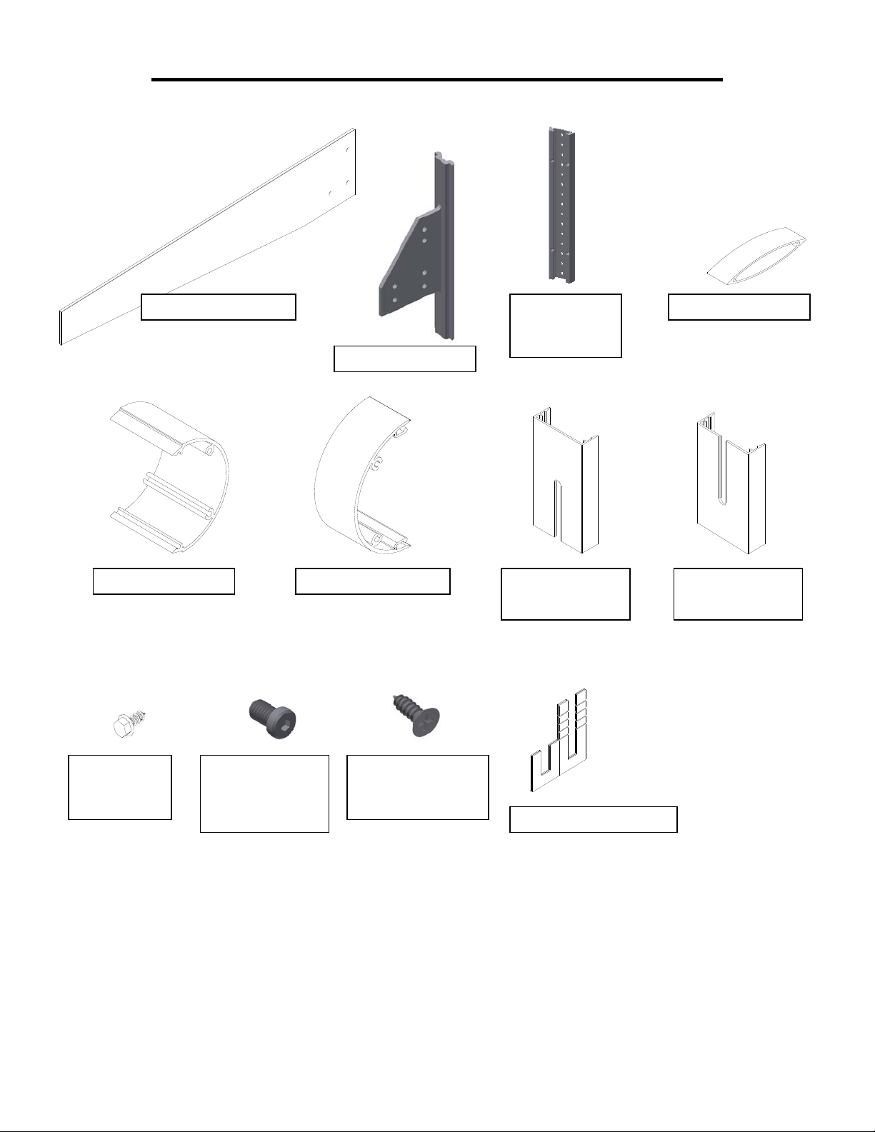
SECTION II: PARTS IDENTIFICATION
-
HADE CLIP
SUNSHADE
PRESSURE
PLATE
-
`
BULLNOSE BASE UPPER COVER
BULLNOSE COVER
W/ NOTCH
LOWER COVER
W/ NOTCH
PRESSURE
PLATE
SCREW
OUT-RIGGER
ARM
ATTACHMENT
SUNSHADE CLIP
ATTACHMENT
SCREW
1/16” POLY-SHIM
EFCO CORPORATION PART #YWSS Page 5 of 19
SERIES 5600 CENTER TONGUE SUNSHADE CLIP INSTALLATION MANUAL 6/2012
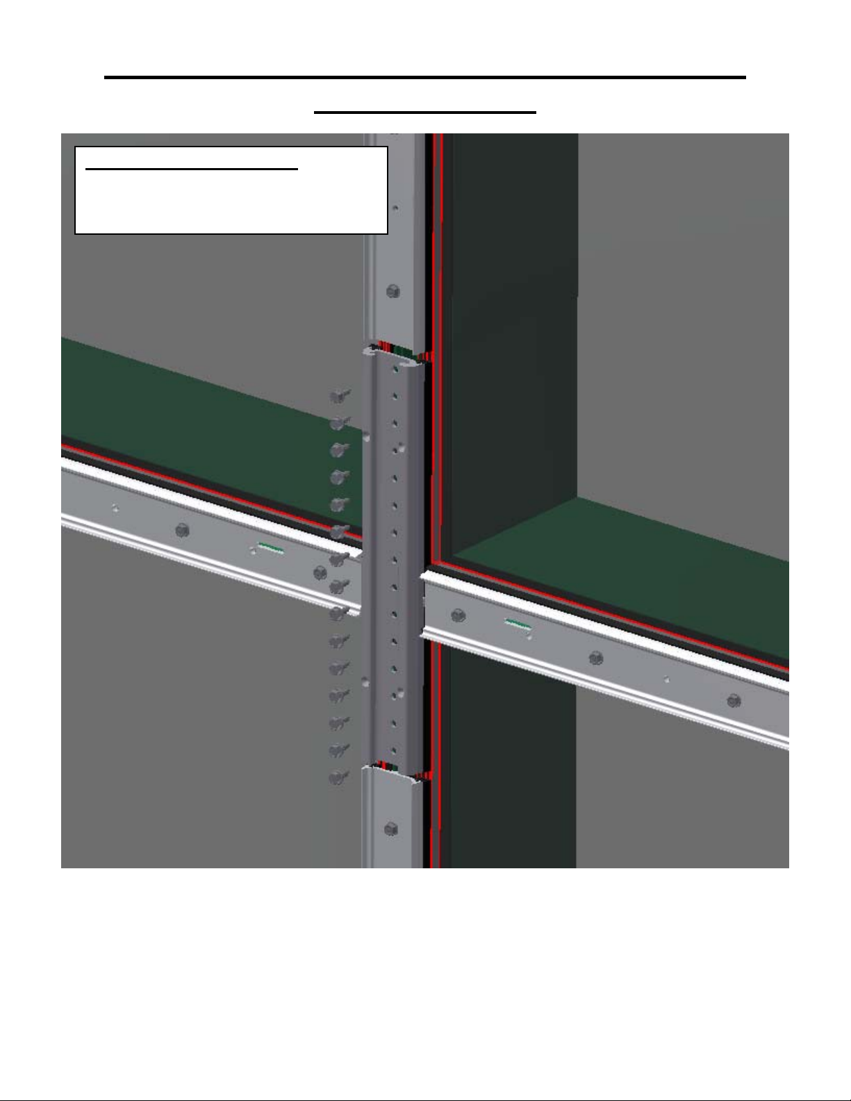
SECTION III: SUNSHADE PRESSURE PLATE
SUNSHADE CLIP LOCATION: THE
SUNSHADE ATTACHMENT DOES NOT
NECESSARILY OCCUR AT THE
HORIZONTAL MULLION LOCATIONS.
ATTACHMENT
Locate the sunshade pressure plate and install with all the adjacent pressure plates. It is crucial that the sunshade
pressure plate be located properly. Half of the pressure plate height will be the centerline for the sunshade clip.
The sunshade pressure plate is 15” in length. Fasten the sunshade pressure plate with the appropriate fasteners
as recommended (Based on structural review and shop drawings). It is recommended to leave 1/8” to ¼” gap
between the sunshade pressure plate and the adjacent vertical pressure plate. This gap will be sealed with
silicone.
EFCO CORPORATION PART #YWSS Page 6 of 19

SERIES 5600 CENTER TONGUE SUNSHADE CLIP INSTALLATION MANUAL 6/2012
SECTION III: SUNSHADE PRESSURE PLATE
ATTACHMENT
TORQUE CLIP ATTACHMENT
SCREWS TO 80 in-pounds.
STARTING AT THE CENTER AND
WORKING TO THE ENDS.
The sunshade pressure plate is now ready to have the sunshade clip slid in place. This may be done now or at a
later time of assembly, but prior to the cover installation.
[AS NOTED].
EFCO CORPORATION PART #YWSS Page 7 of 19

SERIES 5600 CENTER TONGUE SUNSHADE CLIP INSTALLATION MANUAL 6/2012
SECTION IV: SUNSHADE CLIP ATTACHMENT
Slide the sunshade clip into place.
EFCO CORPORATION PART #YWSS Page 8 of 19

SERIES 5600 CENTER TONGUE SUNSHADE CLIP INSTALLATION MANUAL 6/2012
SECTION IV: SUNSHADE CLIP ATTACHMENT
Once located, match drill ( 9/64” dia.) through the four holes in the face of the sunshade pressure plate into th e
sunshade clip and attach with SFZ8 fasteners (#8 x ½” F.H. SMS). Do not drill through the pressure plate into
the glazing pocket.
EFCO CORPORATION PART #YWSS Page 9 of 19

SERIES 5600 CENTER TONGUE SUNSHADE CLIP INSTALLATION MANUAL 6/2012
SECTION V: SUNSHADE CLIP SEALING
ANY & ALL HORIZONTAL TO VERTICAL
PRESSURE PLATE JUNCTIONS ARE TO BE
SEALED IN ACCORDANCE WITH THE
APPROPRIATE SYSTEMS GENERAL
INSTALLATION INSTRUCTIONS.
APPLY SEALANT BETWEEN
THE SUNSHADE PRESSURE
PLATE AND BOTH
PRESSURE PLATES. TOOL
SEALANT INTO JOINT AND
SMOOTH.
SEAL BETWEEN
PRESSURE PLATES,
PROPERLY SEALING
ALL VOIDS.
Sealant must be applied between the pressure plates. Applying sealant after the sunshade clip is in place insures
that the sunshade clip will slide into place.
EFCO CORPORATION PART #YWSS Page 10 of 19

SERIES 5600 CENTER TONGUE SUNSHADE CLIP INSTALLATION MANUAL 6/2012
SECTION VI: SUNSHADE COVER INSTALLATION
LOCATE AND SNAP-ON TOP VERTICAL
MULLION COVER (NOTCH SLOT DOWN).
LOCATE AND SNAP-ON BOTTOM VERTICAL
MULLION COVER (NOTCH SLOT UP)
Locate and fabricate covers to fit over sunshade clip as shown. Snap-on the bottom cover. Then snap-on the top
cover.
Continue to snap on the horizontal covers per individual installation instructions.
Note: This sunshade clip design is to be used with ¾” tall covers as a standard and as a minimum.
EFCO CORPORATION PART #YWSS Page 11 of 19

SERIES 5600 CENTER TONGUE SUNSHADE CLIP INSTALLATION MANUAL 6/2012
SECTION VII: COMPLETED SUNSHADE CLIP
COMPLETED SUNSHADE
CLIP MOUNTING
ATTACHMENT
OPTIONAL: SEAL BETWEEN COVERS
(TOP & BOTTOM) AND SUNSHADE
CLIP (COSMETIC SEAL ONLY)
EFCO CORPORATION PART #YWSS Page 12 of 19

SERIES 5600 CENTER TONGUE SUNSHADE CLIP INSTALLATION MANUAL 6/2012
A
SECTION VIII: SUNSHADE ASSEMBLY
3” BULLNOSE BASE
TERMINATING TUBE
TYPICAL “AIRFOIL” BLADES,
SIZE & SPACING AS DEFINED
BY PROJECT SHOP DRAWINGS
[SEE CURTAIN WALL SUNSHADE
LIMITATIONS FOR STANDARD
ARM AND BLADE LENGTHS]
SUNSHADE ASSEMBLY SECTION
VIII ILLUSTRATES A BEVELED
SUNSHADE APPLICATION. CUSTOM
ASSEMBLIES MAY BE REQUIRED.
REFER TO PROJECT SHOP
DRAWINGS FOR ALTERNATIVE
PPLICATIONS.
ASSEMBLE SUNSHADE IN “LADDER”
SECTIONS BEFORE HOISTING AND
BOLTING BY PAIRS INTO PLACE ON
SUNSHADE ATTACHMENT CLIPS.
SUNSHADE “LADDER”
ASSEMBLY SCREWS
EFCO CORPORATION PART #YWSS Page 13 of 19

SERIES 5600 CENTER TONGUE SUNSHADE CLIP INSTALLATION MANUAL 6/2012
SECTION VIII: SUNSHADE ASSEMBLY
“
”
EFCO CORPORATION PART #YWSS Page 14 of 19

SERIES 5600 CENTER TONGUE SUNSHADE CLIP INSTALLATION MANUAL 6/2012
SECTION IX: SUNSHADE ATTACHMENT
CONTINUE WITH SUNSHADE
ATTACHMENTS DOWN THE LENGTH
OF THE SUNSHADE RUN.
LOOSELY TIGHTEN THE ATTACHMENT BOLTS UNTIL
THE FULL RUN IS IN PLACE. ALIGNMENT OF THE
SUNSHADE “LADDER” SECTION MUST BE COMPLETED
ONE SECTION AT A TIME BEFORE THE BOLTS ARE
TIGHTENED TO A NOMINAL 80 IN-pounds.
EFCO DESIGNS THE SUNSHADE
ATTACHMENT TO REQUIRE
MINIMAL SHIMS. HOWEVER, POLY“SANDWICH” THE SUNSHADE
CLIP WITH A PAIR OF SUNSHADE
ASSEMBLIES.
SHIMS WILL NEED TO BE INSERTED
AS REQUIRED BETWEEN THE CLIP
& THE SUNSHADE ARM.
This particular sunshade is designed to attach one sunshade at a time. Continue with the sunshade attachment
down the sunshade run.
There will be six sunshade arm attachment holes in the sunshade clip. Be sure that the three holes in the
sunshade arm are in the correct location with the sunshade clip for proper alignment of the sunshade arms.
EFCO CORPORATION PART #YWSS Page 15 of 19

SERIES 5600 CENTER TONGUE SUNSHADE CLIP INSTALLATION MANUAL 6/2012
SECTION IX: SUNSHADE ATTACHMENT
FINAL ATTACHMENT OF THE SUNSHADE
ARM WILL LOOK AS SHOWN.
EFCO CORPORATION PART #YWSS Page 16 of 19

SERIES 5600 CENTER TONGUE SUNSHADE CLIP INSTALLATION MANUAL 6/2012
SECTION X: SUNSHADE LEVELING & ALIGNMENT
LEVEL & ALIGN THE TOPS & FACES OF
THE OUT-RIGGER ARMS BEFORE
TORQUING THE ATTACHMENT BOLTS.
NOTE: BULLNOSE BASE SNAPS MUST
ALIGN TO RECEIVE BULLNOSE COVER
EFCO CORPORATION PART #YWSS Page 17 of 19

SERIES 5600 CENTER TONGUE SUNSHADE CLIP INSTALLATION MANUAL 6/2012
SECTION XI: SNAP-ON CONTINUOUS BULLNOSE
COVER
SNAP-ON THE BULLNOSE COVER: DEPENDING ON THE LENGTH OF
THE RUN AND THE ACCURACY OF SUNSHADE LADDER LEVELING
ALIGNMENT; USE OF “C” CLAMPS MAY BE NECESSARY. BE
CAREFUL TO PROTECT THE FINISH FROM BEING MARRED BY THE
“C” CLAMPS AS THEY ARE TIGHTENED TO ENGAGE THE SNAP. ON
LONG RUNS, IT IS HIGHLY RECOMMENDED TO PIN THE COVER BY
MATCH DRILLING THRO UGH THE TOP-SIDE SNAP AND RUNNING
A COUPLE OF #6 SCREWS NEAR THE MID-POINT OF THE RU N.
EFCO CORPORATION PART #YWSS Page 18 of 19

SERIES 5600 CENTER TONGUE SUNSHADE CLIP INSTALLATION MANUAL 6/2012
3
SECTION XI: SNAP-ON CONTINUOUS BULLNOSE
COVER
” BULLNOSE TERMINATING TUBE
* BLADE AND/OR BULLNOSE END CAPS MAY
BE FURNISHED DEPENDING ON THE
TERMINATION OF THE SUNSHADE RUN.
TYPICALLY THESE CAPS ARE SCREW APPLIED
LAST TO DRESS THE EXPOSED ENDS OF THE
SUNSHADE BLADES / BULLNOSE. REFER TO
THE PROJECT SHOP DRAWINGS FOR SPECIFIC
SUNSHADE TERMINATING DETAIL (S).
END CAPS OPTIONAL *
END OF INSTRUCTION
EFCO CORPORATION PART #YWSS Page 19 of 19
 Loading...