

Page 1
NORMAFIX
1
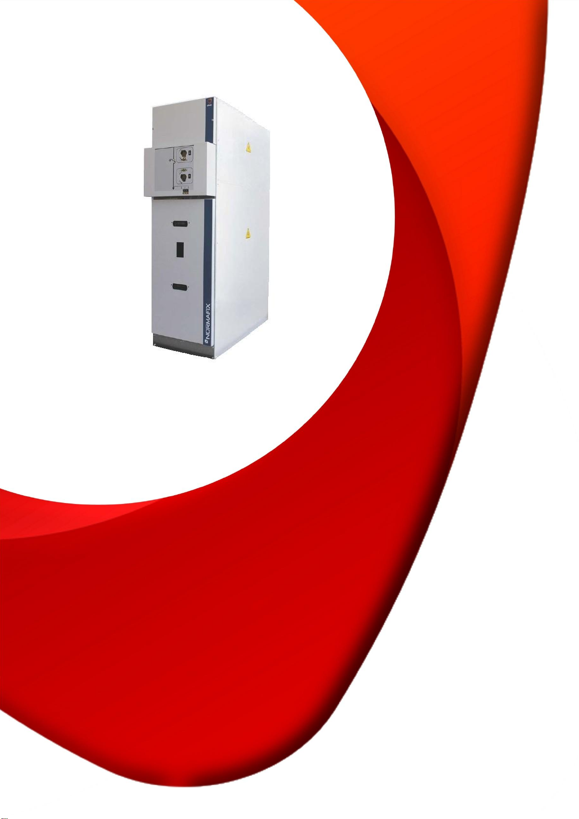
NORMAFIX
Modular Distribution Switchgear
INSTRUCTIONS
Nº453030007
Page 2

1
SECURITY INSTRUCTIONS
NORMAFIX
Read this manual carefully before proceeding with any handling, operation and
maintenance action. Failure to follow safety recommendations, could lead to serious
physical and material injury.
This manual should be accessible to all people involved in the installation, operation and
maintenance of the equipment.
The equipments described in this manual were designed and tested to operate within their
nominal values. Use outside this range may result in malfunction, and could cause serious
physical and material injury.
The cells and switches are equipped with safety interlocks making its use simple and
secure. Do not force them.
This equipment can be remotely controlled and contains live and mechanical parts that
move at high speed.
In the cells with circuit breakers, never perform checks on the circuit-breaker while it is
closed or with the closing springs charged. The circuit breaker must be open and the
closing springs discharged. (See the DIVAC Instruction Manual)
Page 3

NORMAFIX
2
TABLE OF CONTENTS
1. GENERAL TECHNICAL CHARACTERISTICS ...................................................................................................... 3
2. MODULAR UNITS ............................................................................................................................................... 4
2.1 IS Cubicle ................................................................................................................................................... 4
2.2 CIS Cubicle ................................................................................................................................................. 4
2.3 DC Cubicle .................................................................................................................................................. 5
2.4 M Cubicle .................................................................................................................................................... 5
2.5 SBM Cubicle ............................................................................................................................................... 5
2.6 CD Cubicle .................................................................................................................................................. 6
2.7 TT Cubicle .................................................................................................................................................. 6
2.8 DB Cubicle .................................................................................................................................................. 6
3. OVERVIEW OF MODULAR UNITS ..................................................................................................................... 7
4. OPERATING MECHANISMS .............................................................................................................................. 10
5. SF6 SYSTEM ..................................................................................................................................................... 12
6. DISPATCH ........................................................................................................................................................ 13
7. RECEPTION ...................................................................................................................................................... 13
8. INSTALLATION ................................................................................................................................................ 14
8.1 Preparing the floor ................................ ................................ ................................................................ . 14
8.2 Unpacking................................................................................................................................................. 14
8.3 Installation on site .................................................................................................................................. 14
8.4 Panels assembly ...................................................................................................................................... 15
8.5 Fastening the panels to the floor......................................................................................................... 15
8.6 Connection of the earthing circuit ...................................................................................................... 16
8.7 Busbar connection .................................................................................................................................. 16
8.8 Cables connection .................................................................................................................................. 17
8.9 Toroidal transformers Cable Connections .......................................................................................... 19
8.10 Assembling of fuses .............................................................................................................................. 19
8.11 Definition of fuses ................................................................................................................................ 20
9. START-UP ........................................................................................................................................................ 20
9.1 Essential checking .................................................................................................................................. 20
9.2 Switchgear operations ........................................................................................................................... 20
9.3 Voltage feeding ....................................................................................................................................... 20
9.4 Live cables control ................................................................................................................................. 21
9.5 Phase agreement control in “Incoming” panels ................................................................................ 21
9.6 Busbar feeding and fuses protection ................................................................................................... 21
10. EXPLOITATION .............................................................................................................................................. 22
10.1. Operating mechanism operation ...................................................................................................... 22
10.2. Earth Switch opening operation (CI1 and CI2) ............................................................................... 22
10.3. Earth Switch closing operation (CI1 and CI2) ................................................................ ................. 23
10.4. Switch closing operation (CI1 or CS1) .............................................................................................. 23
10.5. Switch opening operation (CI1 or CS1) ............................................................................................ 24
10.6. Switch closing operation and recharge for opening (CI2 - transformer protection function) 24
10.7. Switch opening operation (CI2 - transformer protection function) ............................................ 25
10.8. Closing and opening operations (Vacuum Circuit Breaker, CDV mechanism) ........................... 25
10.9. Closing and opening operations (SF6 Circuit Breaker, CLR mechanism) ................................... 26
12. REPLACEMENT .............................................................................................................................................. 27
12.1 Replacing the Voltage Signalization lamps ...................................................................................... 27
12.2 Fuse replacement ................................ ................................ ................................................................ . 27
12.3 Removing the automatic switch disconnector of the cubicle ....................................................... 28
12.4 Removing cover mechanism ................................................................................................................ 29
13. SPARE PARTS ................................................................................................................................................ 29
Page 4

3
1. GENERAL TECHNICAL CHARACTERISTICS
Rated voltage
12 kV
17,5 kV
24 kV
36 kV
Insulation level
- Power frequency (Hz - 1min)
28 kV
38 kV
50 kV
70 kV
-Lightning impulse (1,2 / 50s)
75 kV
95 kV
125 kV
170 kV
Rated current
Busbar
630 A
630 A
630 A
630 A
Incoming/Outgoing
400 A
630 A
400 A
630 A
400 A
630 A
400 A
630 A
Fuses Protection
200 A
200 A
200 A
200 A
Circuit-Breaker Protection
630 A
630 A
630 A
630 A
Rated short-time current
16 (3s) kA
20 (1s) kA
16 (3s) kA
20 (1s) kA
16 (3s) kA
20 (1s) kA
16 (3s) kA
Making capacity
40 kA
50 kA
40 kA
50 kA
40 kA
50 kA
40 kA
Frequency
50 Hz
50 Hz
50 Hz
50 Hz
Internal Arc (IAC A-FL)
16 kA (1s)
16 kA (1s)
16 kA (1s)
16 kA (1s)
Ambient temperature
-5 a 40 ºC
-5 a 40 ºC
-5 a 40 ºC
-5 a 40 ºC
Rated filling pressure (20ºC)
0,3 bar rel
0,3 bar rel
0,3 bar rel
0,3 bar rel
Category of loss of service continuity
LSC 2A (according to CEI 62271-200)
Class partition
PI (according to CEI 62271-200)
Degrees of protection (CEI 60529 e EN 50102)
IP65 (medium voltage compartment)
IP3XC (mechanism compartment)
IP 3XC (cable compartment)
IK09 (medium voltage compartment)
IK08
Standard colour
RAL 7035
Panel type
Width (mm)
Height** (mm)
Depth* (mm)
Weight (kg)
IS
375
1575 (+400)
860 (+110)
100
CIS
375
1575 (+400)
860 (+110)
110
DC
750***
1575 (+400)
860 (+110)
355
CD
375
1575 (+400)
860 (+110)
80
M
750
1575 (+400)
860 (+30)
175
SBM
750
1575 (+400)
860 (+110)
200
TT
500
1575 (+400)
860 (+110)
150
DB
750
1575 (+400)
860 (+110)
460
NORMAFIX
Panels dimensions up to 24 kV
* Depth of 860 mm for the standard cubicle, adding 110 mm for the operating mechanism.
** Height of 1575 mm for the standard cubicle, adding 400 mm for the top compartment.
*** Width of 750 mm for the standard cubicle, adding 250mm if cubicle is equipped with voltage
transformers.
Page 5
NORMAFIX
4
Panel type
Width (mm)
Height** (mm)
Depth* (mm)
Weight (kg)
IS
600
2010 (+400)
1155 (+110)
275
CIS
600
2010 (+400)
1155 (+110)
300
DC
1200
2010 (+400)
1155 (+110)
900
CD
600
2010 (+400)
1155 (+110)
245 M 1200
2010 (+400)
1155 (+30)
470
SBM
1200
2010 (+400)
1155 (+110)
560
TT
600
2010 (+400)
1155 (+110)
420
DB
1200
2010 (+400)
1155 (+110)
1000
Switch Disconnector
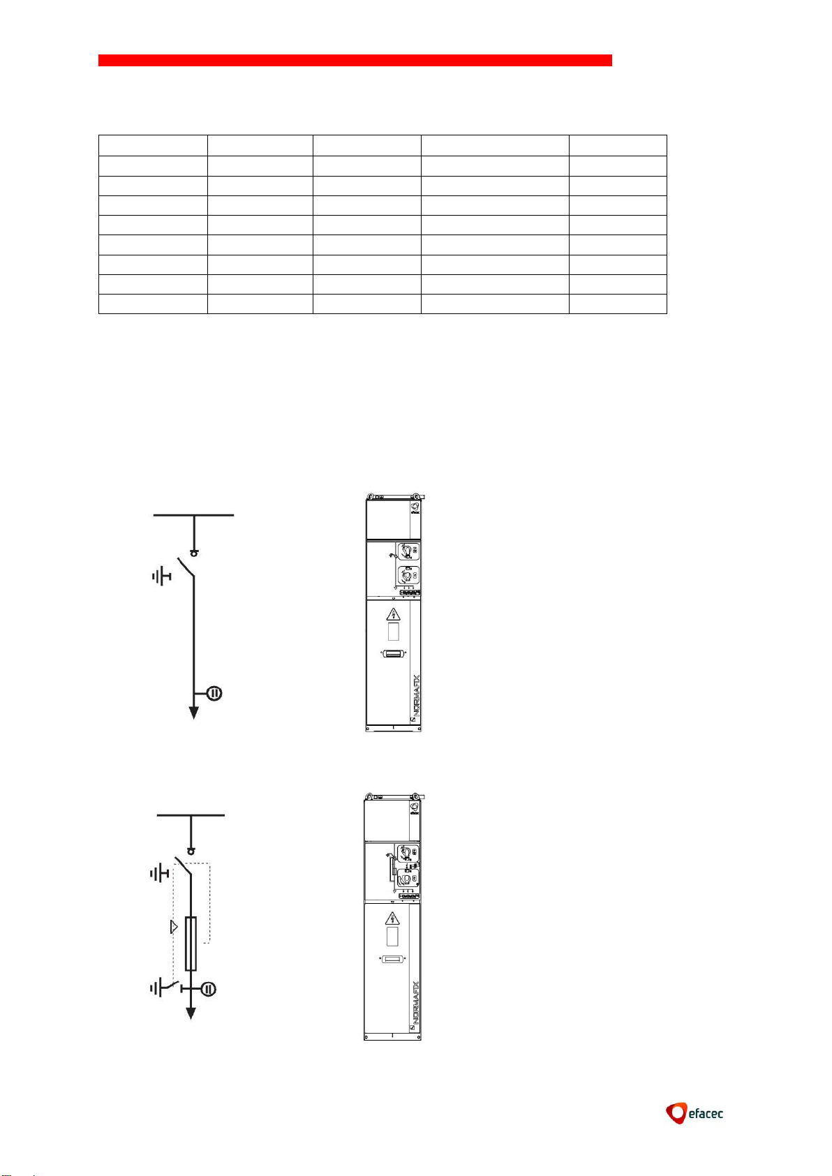
Cubicle (IS)
Cubicle for incoming/outgoing
cable equipped with switch
disconnector ISF (with
operation mechanism CI1).
Transformer Protection
Cubicle (CIS)
Cubicle for transformer
protection by fuses, equipped
with switch disconnector ISF
(with operation mechanism
CI2).
Panels dimensions of 36 kV
* Depth of 1155 mm for the standard cubicle, adding 110 mm for the operating mechanism.
** Height of 2010 mm for the standard cubicle, adding 400 mm for the top compartment.
2. MODULAR UNITS
2.1 IS Cubicle
2.2 CIS Cubicle
Page 6
5
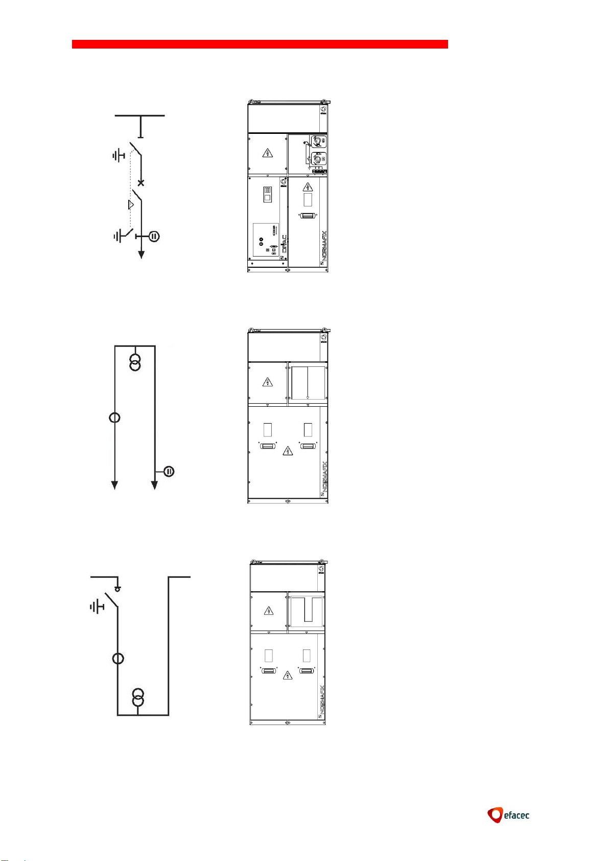
2.3 DC Cubicle
Cables Protection Cubicle
(DC) with circuit breaker.
The circuit breaker
interrupting technology can
be vacuum (DIVAC type) or
SF6 (DIFLU type).
Measure Cubicle (M)
Cubicle for measuring current
and/or voltage.
Different versions are
available:
- Lateral incoming and
outgoing;
- Incoming and outgoing by
cable;
- Incoming by cable and
lateral outgoing.
Sectioning and Measure (SBM)
Cubicle for sectioning and
measuring the current and/or
voltage.
Versions are available with
the right or left rise.
2.4 M Cubicle
NORMAFIX
2.5 SBM Cubicle
Page 7
6
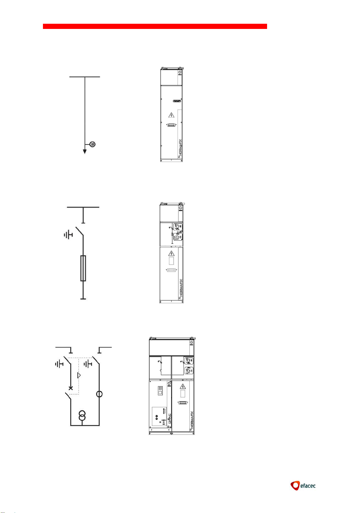
Direct Incoming Cubicle (CD)
Cubicle incoming or outgoing
cables direct.
Voltage Transformer
Cubicle (TT)
Cubicle for measure voltage
with protection of VT’s by
fuses.
Bars Protection Cubicle (DB)
Cubicle for protection bars
and measuring the current
and/or voltage.
Versions are available with
arrival to the right or left.
2.6 CD Cubicle
2.7 TT Cubicle
NORMAFIX
2.8 DB Cubicle
Page 8
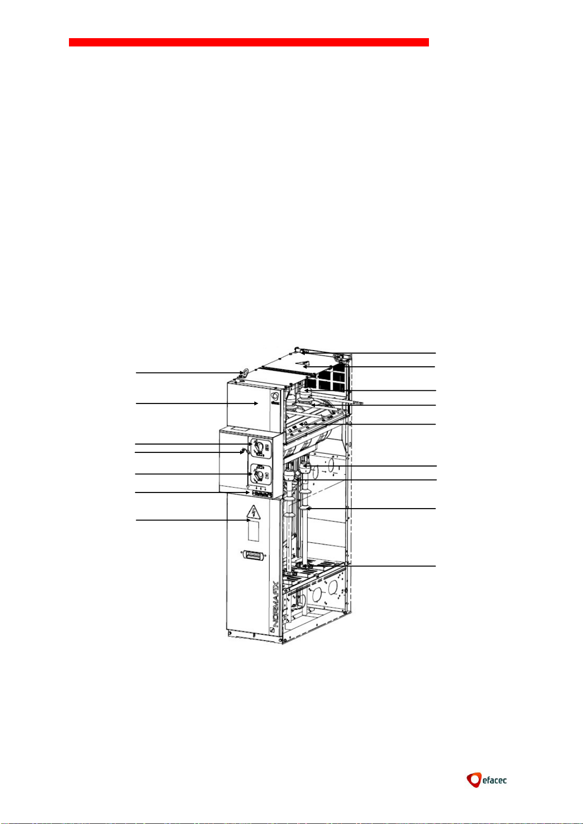
7
3. OVERVIEW OF MODULAR UNITS
9
10
15
11
16 7 4
2 1 12
13
14
5 6 3
8
Cubicle IS
1- Accessories for lifting the cubicle
2- Low voltage compartment
3- Earth switch operating mechanism
4- Mechanical synoptic state of the switch disconnector
5- Switch disconnector operating mechanism
6- Live cables signalling neon lamps
7- Cable compartment access door
8- Earth main bar
9- Busbar access panel
10- Busbar deflector Cover
11- Busbar
12- ISF Switch Disconnector
Die for cable connection MT
1314- Capacitive insulator of support
15- MV Cables
16- Tightening of cables
NORMAFIX
Page 9

8
Cubicle CIS
9
18
10
19
7 4 2
1
11
12
14
5
6
3
8
15
13
16
17
1- Accessories for lifting the cubicle
2- Low voltage compartment
3- Mechanical synoptic state of the switch disconnector
4- Earth switch operating mechanism
5- Switch disconnector operating mechanism
6- Live cables signalling neon lamps
7- MV Cables acess painel
8- Earth circuit
9- Busbar access panel
10-Busbar deflector
11- ISF Switch Disconnector
12- Fire system protection fuse
13- Upper fuse support
14- MV Fuses
15- Bottom fuse support
16- Capacitive insulator of support
17- Additional Earth switch
18- MV Cables
19- Tightening of cables
NORMAFIX
Page 10
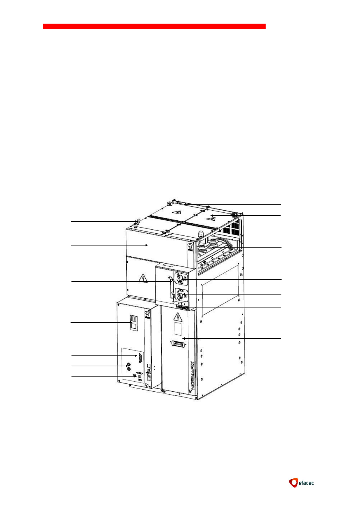
9
Cubicle DC
2
1
8
9
10
3
4
6 7 5
11
12
13
14
1- Accessories for lifting the cubicle
2- Low voltage compartment
3- Mechanical synoptic state of switch disconnector
4- Self-powered protection relay
5- Hole insert lever (charging the springs of circuit breaker)
6- Button to open and close the circuit breaker
7- Mechanical synoptic state of circuit-breaker
8- Earth main bar
9- Busbar access panel
10- Disconnector SF
11- Earth switch operating mechanism
12- Disconnector operating mechanism
13- Live cables signaling neon lamps
14- MV Cables access panel
NORMAFIX
Page 11
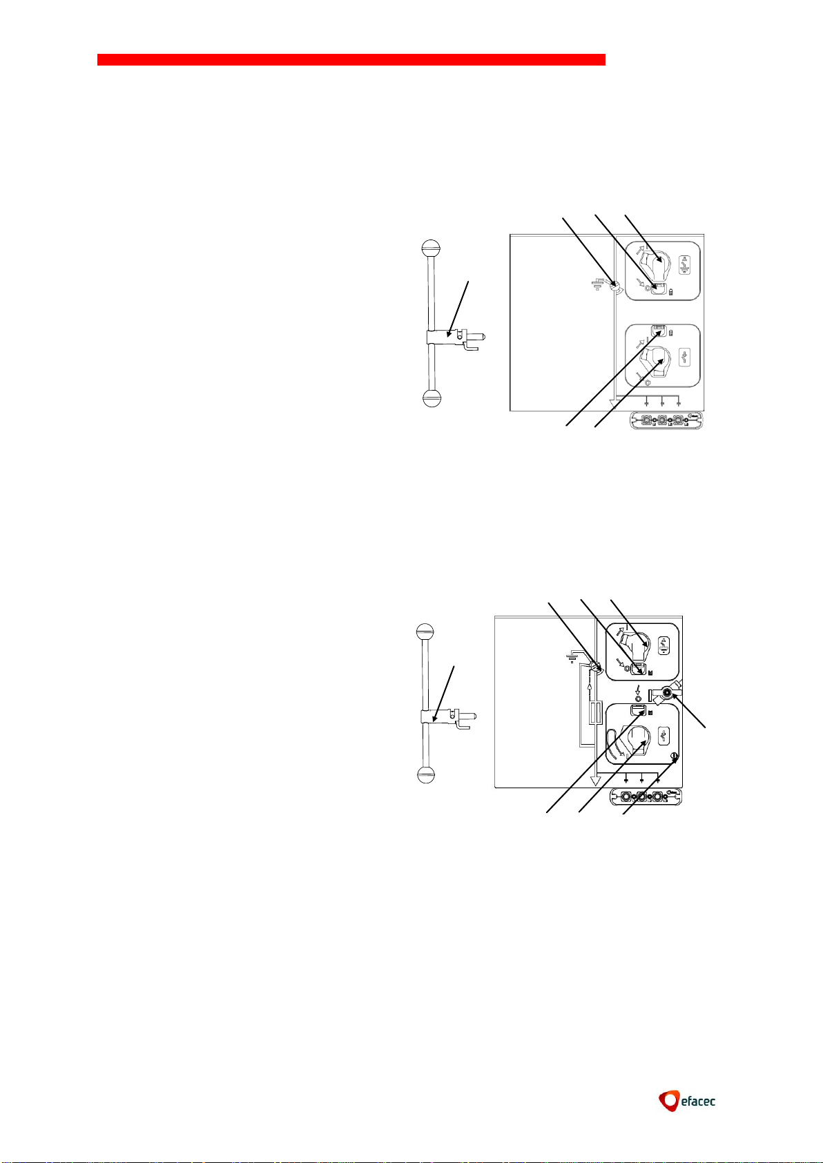
NORMAFIX
10
1 – Lever for the manual operation of the switch
or the earthing switch
2 – Switch Disconnector status indicator
Operating mechanism Earth switch:
3 – Hole to insert Earth Switch interlocking pin
4 – Hole for operating lever of the earth switch
Operating mechanism Switch Disconnector (or
Disconnector):
5 – Hole to insert Switch Disconnector
interlocking pin
6 – Hole for operating lever of the Switch
Disconnector
1 – Operating lever tol Switch Disconnector and
Earth Switch
2 – Synoptic to indicate mechanical state of the
Switch Disconnector and earth switch
Operating mechanism Earth Switch:
3 – Hole to insert Earth Switch interlocking pin
4 – Hole for operating lever of the earth switch
CI2 Operating mechanism Switch Disconnector
(Only CIS cubicles):
7 – Hole to insert Switch Disconnector
interlocking pin
8 – Hole for operating lever of the Switch
Disconnector
9 – Fuse fusion signaling
10 – Button for manual opening of Switch
Disconnector
1
5
6
2 4 3
1
7
8
2 4 3
9
10
4. OPERATING MECHANISMS
Operating Mechanism CI1, CS1 e CST (Switch Disconnector and Earth Switch)
Operating mechanism CI2 (Switch Disconnector and Earth Switch)
Operating mechanism functional principle CI1(M), CI2(M), CS1, CST
The maneuver of a lever drags a spring away from a balanced position. In this position,
releases the spring stretching up abruptly and independently of the operator.
Page 12
NORMAFIX
11
FUNCTIONAL PRINCIPLE
APPLICATION EXAMPLES
CI1(M)
“Tumbler” type operating mechanism.
Opening and closing operations are manually
or electrically performed with a speed
independent from the operator's action.
(Recharging time <= 10s at Un)
Feeder function equipment (set a net to
service or remove it from service) and
transformer fuse protection (load
protection through ISF fuses without
tripping). CI1M enables the ISF remote
switch operation.
CI2(M)
“Tumbler” type operating mechanism.
Equipped with stored-energy spring system
exclusively for opening. The closing
operation is followed by a recharge
operation that enables an eventual opening
operation in less than 100 ms through a
release magnet, a fuse or a push-button
Switch tripping by means of one or
more Fuses.
Switch tripping due to transformers
protection relays.
Switch opening.
CS1
Double function operating mechanism with
dependent operations for the SF switch and
independent operations for the cable
earthing switch (DC panels).
Enables the simultaneous control of two
SF switches (DB panels)
CST
Earthing switch operating mechanism.
Closing and opening speed are independent
from the operator’s action.
Enables the CD panel earthing
switchcontrol
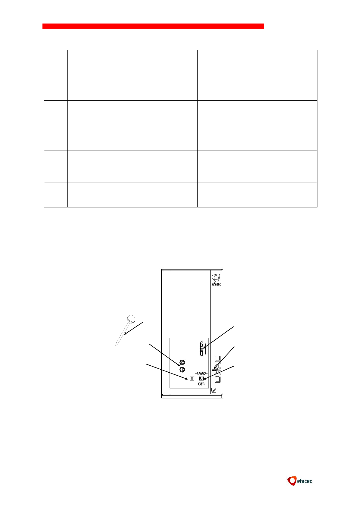
1 – Lever (charging system the springs of circuit
breaker)
2 – Button to open and close the circuit breaker
3 – Mechanical synoptic state of circuit breaker
4 – Hole to insert lever (charging system the
springs)
5 – Maneuvers counter
6 – Mechanical synoptic state of springs
1
4 3 5 6 2
CDV Mechanism (Vacuum Circuit-Breaker)
Page 13

12
CLR mechanism (SF6 circuit breaker)
1 – Lever (charging system the springs of circuit
breaker
2 – Maniple for open and close the circuit
breaker
3 – Mechanical synoptic state of circuit breaker
4 – Mechanical synoptic state of springs
5 – Maneuvers counter
6 – Hole to insert lever (charging system the
springs)
Supplier: EFACEC
Model: 37409072
Dimensions: DN14,5
The valve is resistant to decomposing SF6.
1
4 3 5 6 2
NORMAFIX
5. SF6 SYSTEM
The ISF switches and SF isolators, of insulation in SF6, used in the NORMAFIX cells are
devices that are watertight and sealed for life (according to IEC 62271).
The tightness of this equipment is guaranteed by routine tests performed. The expected
life of this equipment is 30 years.
To access the valve it is necessary to remove the hood of the engine command (see
instructions in this manual.)
Features of the valve used:
Operations to remove the SF6 Switches shall be conducted by EFACEC technicians.
Page 14
NORMAFIX
13
120º Max
6. DISPATCH
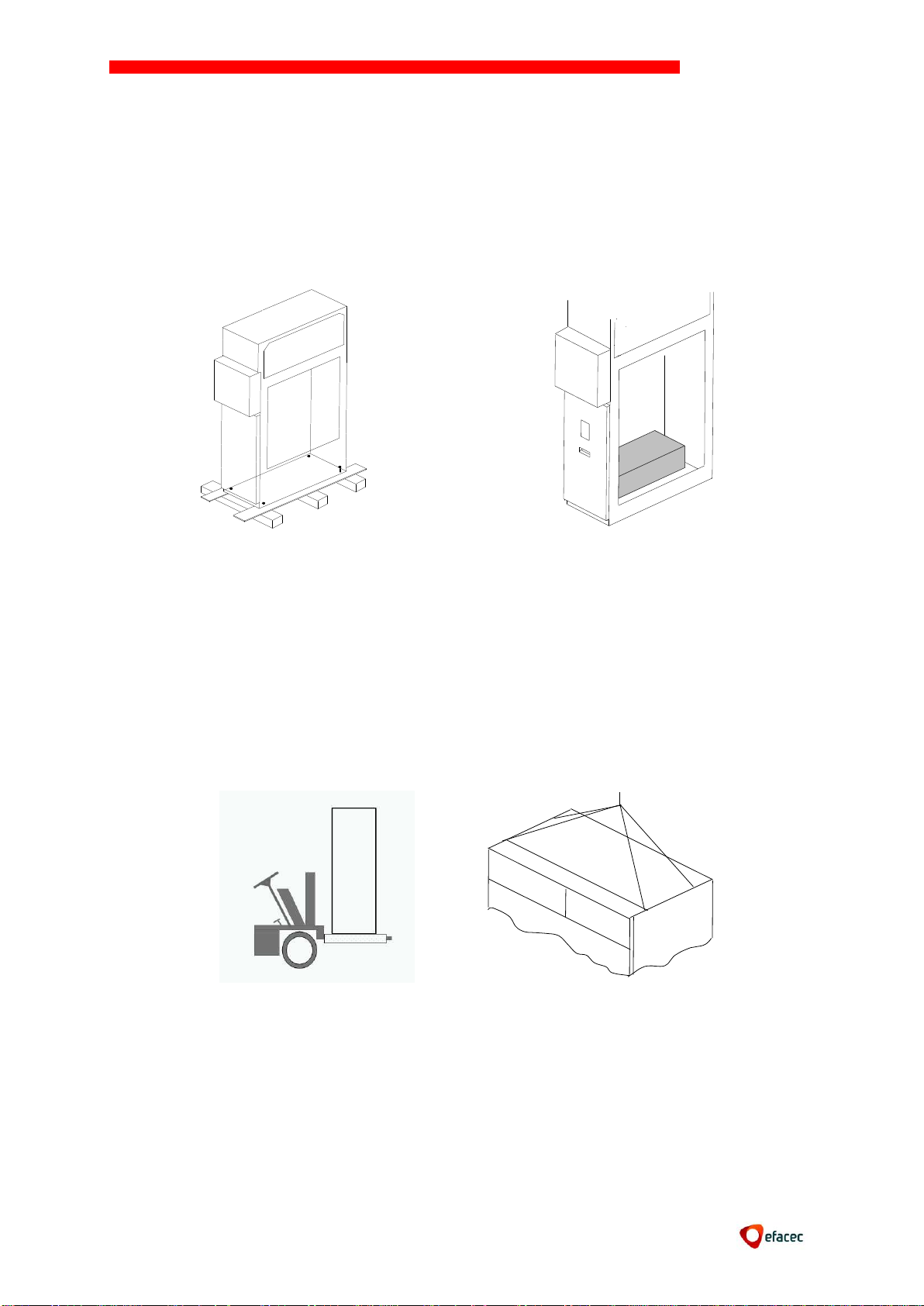
The NORMAFIX cells are shipped with the switch open and the earthing switch closed.
The NORMAFIX cells are shipped individually on a wooden pallet (fixed by four screws and
covered with transparent plastic film).
Accessories for mounting and wiring of the cells are supplied separately.
7. RECEPTION
Identify and confirm in the panels received:
The function through the synoptic
The rating plate
The good condition of the material
Confirm the existence of the separated material package.
Any irregularities found, should be mentioned in the delivery note.
Panels must remain fixed to the transportation wooden pallet until assembled. Panels are
displaced with the help of the following tools:
Travelling crane
Pallet-carrier
For the safety of the operator and the equipment itself, the units must be transported
laterally.
Page 15
NORMAFIX
14
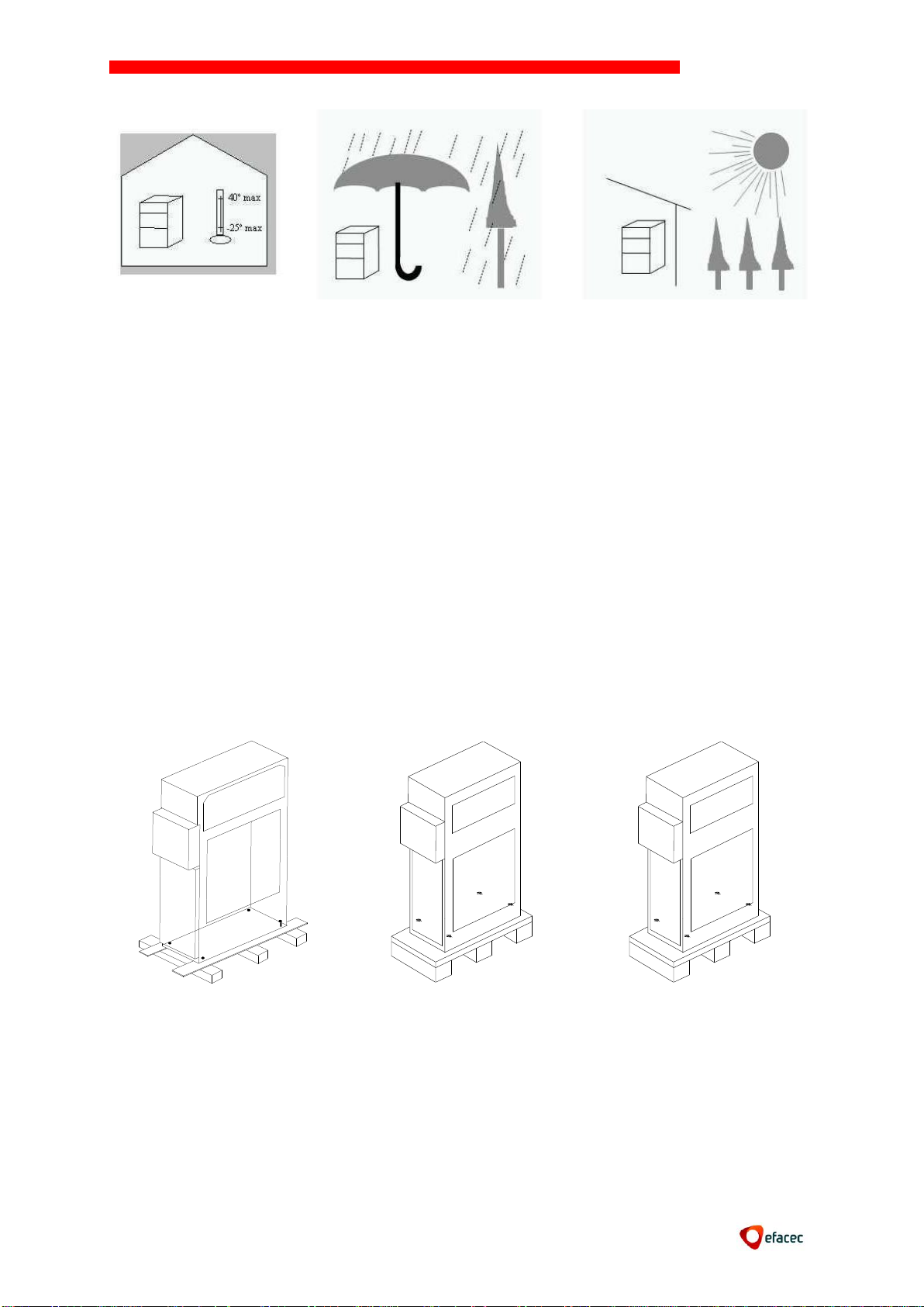
The panels should be stored with its original packaging, to avoid dust, splashing water and
chemicals, in a well ventilated and dry area, at a temperature between -25°C and +40°C.
8. INSTALLATION
8.1 Preparing the floor
The floor maximum admissible unevenness is of 2 mm/m in order to allow an easy
mounting and a good final appearance of the panels set.
8.2 Unpacking
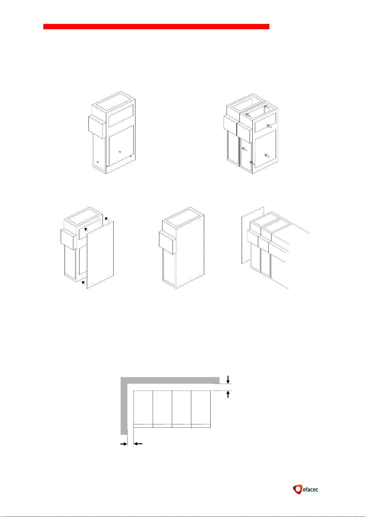
Once the panels are near the assembly place and in the foreseen order:
Remove the plastic film;
Open the cable compartment door (earthing switch must be in the closed position);
Remove the four screws (wrench 17) holding the cubicle to the base;
Rotate the panel in order to release it from the base and place it on the floor
according to movement instructions.
8.3 Installation on site
Removed the access to the cable compartment;
Check the verticality, using pads if necessary;
Fix it to the ground.
Page 16
NORMAFIX
15
20 mm
200 mm
8.4 Panels assembly
Position the first panel and fix it to the floor.
Then, position the second panel and connect it to the first by using M8x16H screws, M8
washers and M8H nuts and fix it to the floor. Do the same for the remaining cubicles.
It is necessary to place the side end panels at the end of the set of cells. They use 14 M6
screws, washers and riveted nuts (supplied as accessories) to attach each panel.
Note: The assembly should be done with the roof panel to access the bus and cable
compartment door removed.
8.5 Fastening the panels to the floor
Refer to the deployment plan of the panels where its configuration is set, the overall
dimensions and recommended points of attachment to the floor.
The panels are fixed to the ground by means of M12 screws (4 attachment points in the end
cells, and two diagonal fixing points in the others).
Page 17
NORMAFIX
16
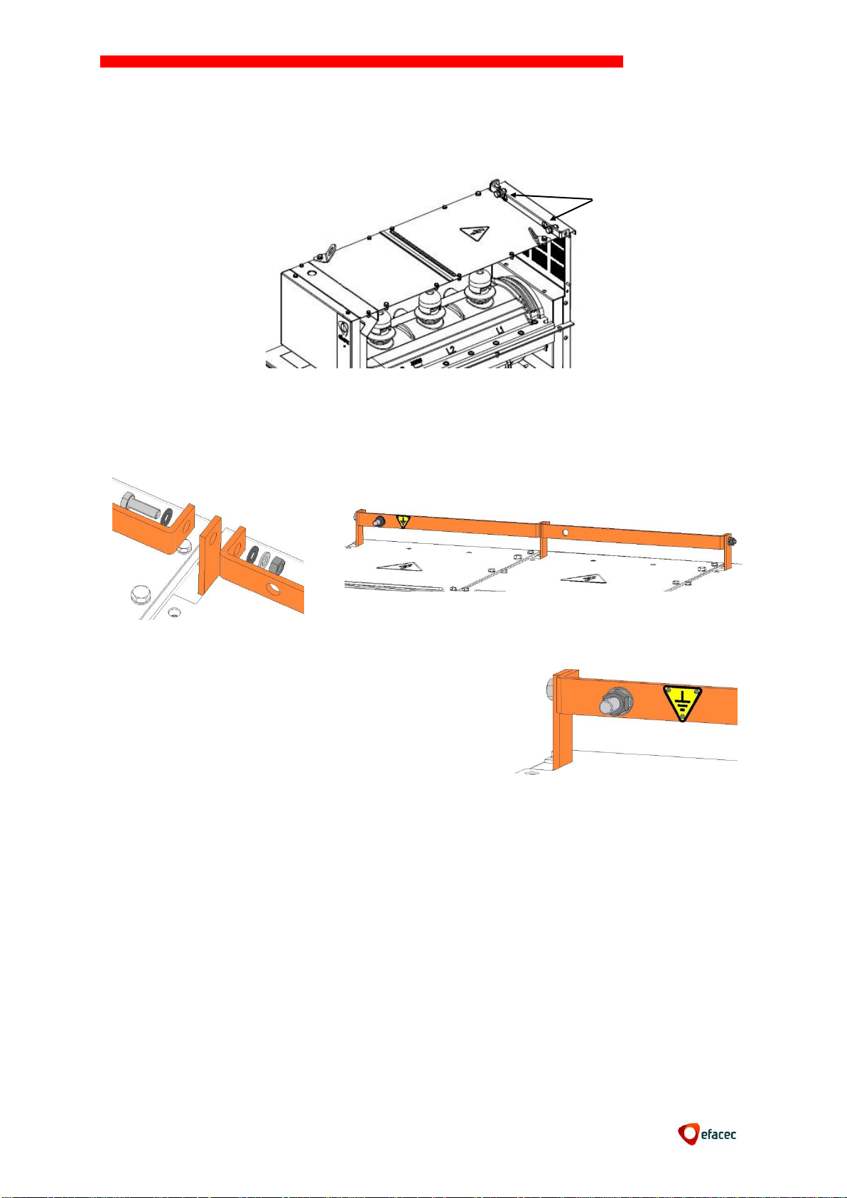
In the cell at the edge of the frame, turn the general
collector to the protective earth of the installation
through a copper conductor of 50 mm², M8H bolt,
washer and nut (binary 1.9 daNm)
(*)
8.6 Connection of the earthing circuit
All NORMAFIX components (bars, cables connections, fuses, etc.) are interconnected and
connected to the earth by the same copper circuit.
(*) – Points of connection of the busbar circuit common ground
Tighten the copper bars of the circuit ground to ensure continuity.
Tighten the M8H nuts with 0.9 daNm binary.
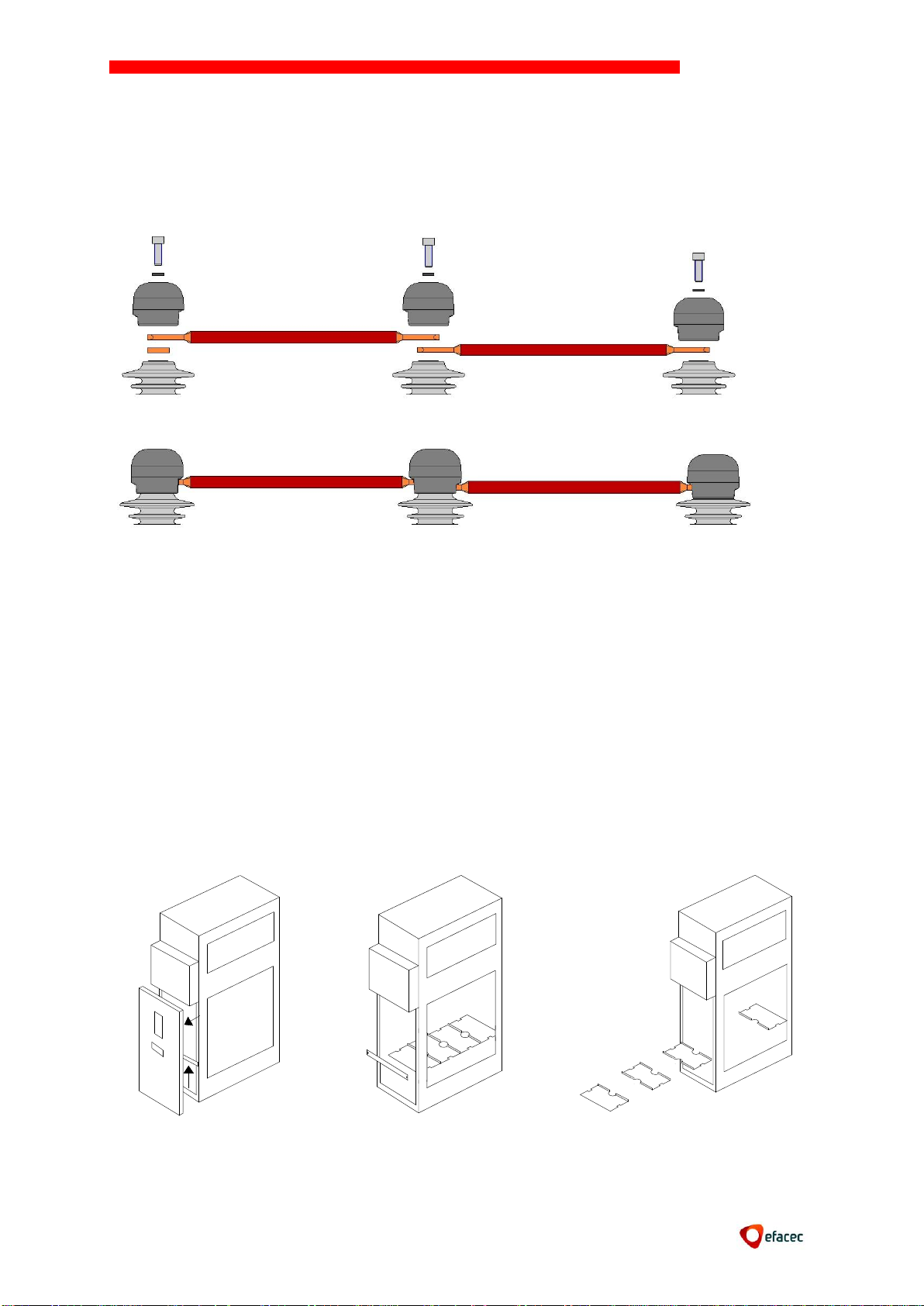
8.7 Busbar connection
It is not necessary to prepare the contact surfaces (eventually, a simple dust cleaning).
However, if the panels have been stored for a long time, check the contacts for oxidation.
Starting at a switchboard end and always at the rear phase L1.
To access the bus it is necessary to remove the access panels (top of the panel).
Page 18
NORMAFIX
17
2
1
Starting at a switchboard end and at the rear phase L1:
Arrange the bars over the upper sockets;
Place the deflectors, screws and washers in position (orient the deflectors on the
correct position);
Immobilize the fixing screws with a fastening binary of 2,4 daNm, wrench 17.
8.8 Cables connection
NORMAFIX was designed for use with cable, shrink or silicon terminals. The selection of the
cables and cable terminals are the responsibility of the customer. The materials should be
compatible with the NORMAFIX equipment.
To access the cable compartment and work safely, you must open the load break
disconnector switch and close the earthing switch.
Remove the cable access panel;
Dismantle the lower front crossbar (2 nuts, wrench 13);
Dismantle the medium front crossbar (2 nuts, wrench 13);
Extract the first three elements of the bottom plate;
Page 19
NORMAFIX
18
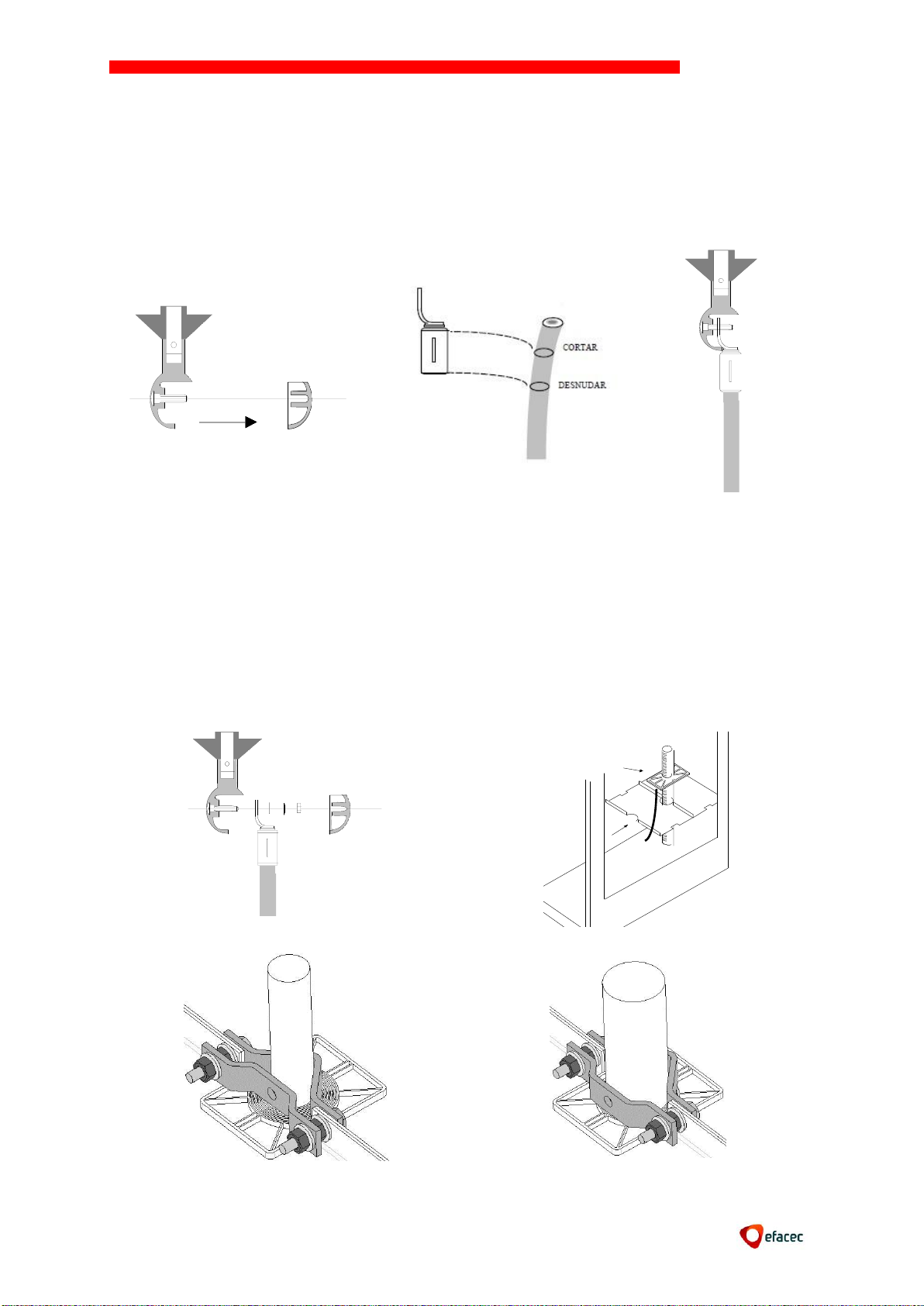
Access the current switch screw where the terminal is fixed to the cable (on the
panels IS and CD it is necessary to remove the deflector);
Place the cables at terminal height, starting by the furthest phase;
Mark the terminal lower limit on the cables;
Pull the cables outside and execute the ends following the cable manufacturer's
instruction;
Starting from the farther phase, locate the current terminal and fasten the screw
with the nut and washer - tightening torque 4,5 daNm (and,
replacing the deflector in the IS and CIS);
Assemble the second element of the bottom plate, taking care to leave the cable
earth plait above the plate.
Cut the cable bushing according with the cable outside diameter and insert it down
the cable to the bottom plate.
Adapt the tightening clamps and immobilise the nuts (wrench 13), being careful not
to overtorque the cable.
Page 20
NORMAFIX
19
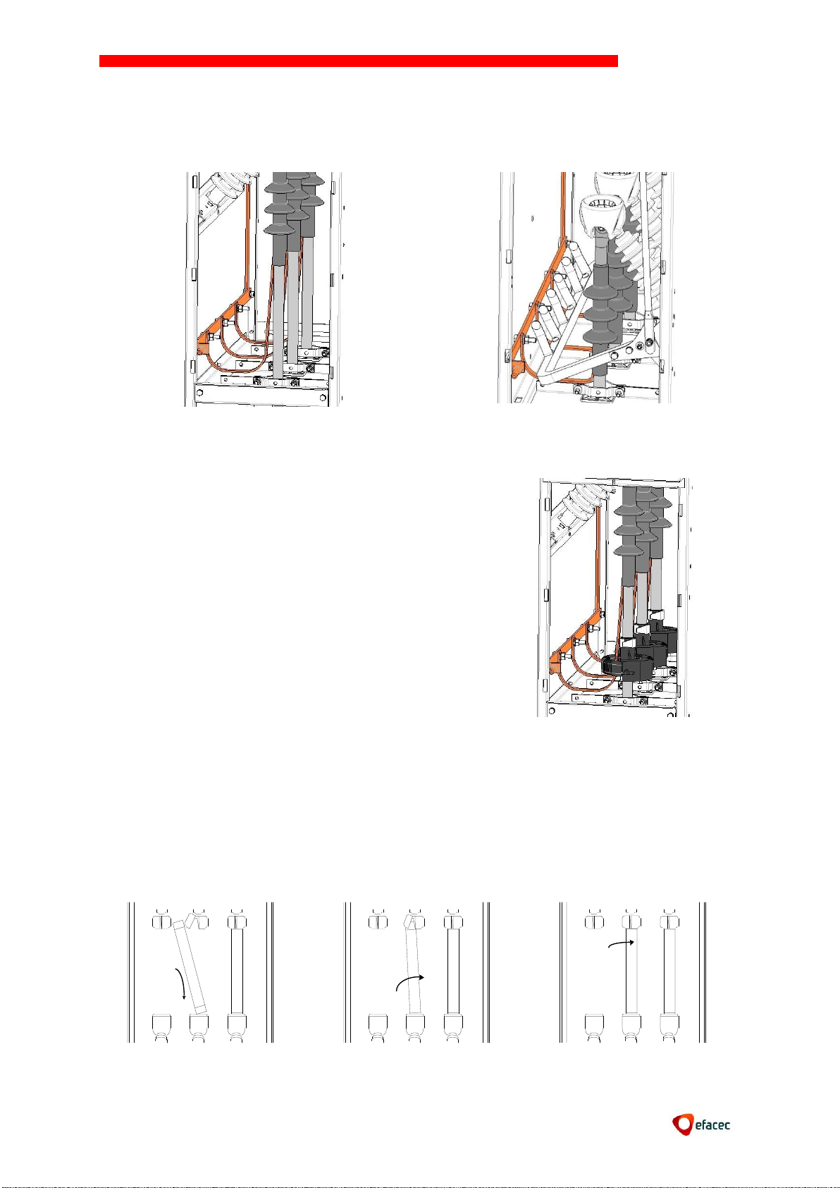
It is possible to install toroidal current sensors in
fault detector’s cables.
To assure its correct operation, it is necessary to
confirm that the earth cable connection is made
from the interior of the current sensors.
Connect the three cable earth plaits to the earth main bar with M8x30H screws and
immobilize the nut with a wrench 13, tightening torque 0,9 daNm.
8.9 Toroidal transformers Cable Connections
8.10 Assembling of fuses
Proceed as indicated in figures:
Using the fuse itself, rise the fuse holder upper shell cover;
Fit the fuse lower part into the fuses holder lower shell;
Fit the fuse upper part into the fuses holder upper shell making sure that the upper
shell cover is correctly closed;
The fuse should not be held by its central part.
Page 21

NORMAFIX
20
Power of
transformer
Transformer - primary voltage
10/11 kV
13.8 kV
15kV
20kV
24/25 kV
30 kV
kVA
Rated current (A) IN (**)
100
16
10
10
10
10
10
125
16
16
10
10
10
10
160
20
16
16
16
10
10
200
25
20
16
16
16
10
250
31.5
25
20
16
16
10
315
40
31.5
25
20
20
16
400
50
40
31.5
25
25
16
500
63
50
40
31.5
31.5
20
630
80
63
50
40
40
25
800
100
80
63
50
50
31,5
1000
125
100
80
63
63
40
1250
160
125
100
80
80
50
1600
160
(*)
125
100
(*)
(*)
2000
250
(*)
(*)
(*)
(*)
(*)
In the case of fuses with striker:
Remove the label of protection of the striker, when installing the fuse for the first
time;
Make sure the striker is positioned correctly (upwards).
8.11 Definition of fuses
(*) The fuse definition must consider the power loss limits (indicated in the fuse documentation)
(**)To (IN a: –5ºC T +40ºC) and power transformer > 1000 kVA, the maximum intensity
of service 1.2 x IS.
9. START-UP
9.1 Essential checking
Confirm the proper connection of the busbar, cable, earth circuits, measuring TF’s
and auxiliary LV circuits;
Confirm the proper assembly of the fuses, busbar and cable field deflectors and
cable compartment panels;
Confirm that the pressure indicator (if applicable) is in the green zone
9.2 Switchgear operations
Confirm the proper functioning of the equipment and of the interlocking, by
operating the Switch and the Earthing Switch.
9.3 Voltage feeding
Confirm that all devices are in “open” position.
Page 22
NORMAFIX
21
9.4 Live cables control
After having fed the cubicle "A" cables, check whether the L1, L2, L3 live cables
indicating lamps, mounted in the operation panel, are lit;
Feed cubicle "B" cables and check the lighting of the live cables indicating lamps.
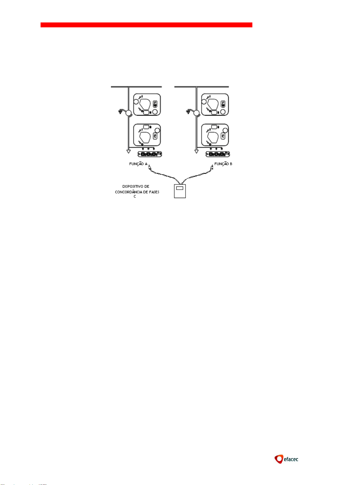
9.5 Phase agreement control in “Incoming” panels
Check the phase agreement using the movable control device "C" for that purpose:
- Insert the "C" male plug into the panel “A” L3 device test socket.
- Insert the lead male plug into the panel “B” L3 device test socket.
If there is phase agreement:
- Panels A and B L3 control device lamps are lit.
- The movable device "C" lamp is switched off.
If there is phase disagreement:
- Panels A and B L3 control device lamps have reduced luminosity.
- The movable device "C" lamp switches on.
- Repeat the same operations for phases L1 and L2.
Remark: In order to confirm the proper functioning of the phase agreement movable
device, connect the two plugs of the later to two phases of the same cubicle: the lamp
should switch on.
9.6 Busbar feeding and fuses protection
Close the incoming panels(s) switch(es);
Close the outgoing panels and general protection switch;
Check whether the L1, L2, L3 live cables indicating lamps of this last panel are lit.
Page 23
NORMAFIX
22
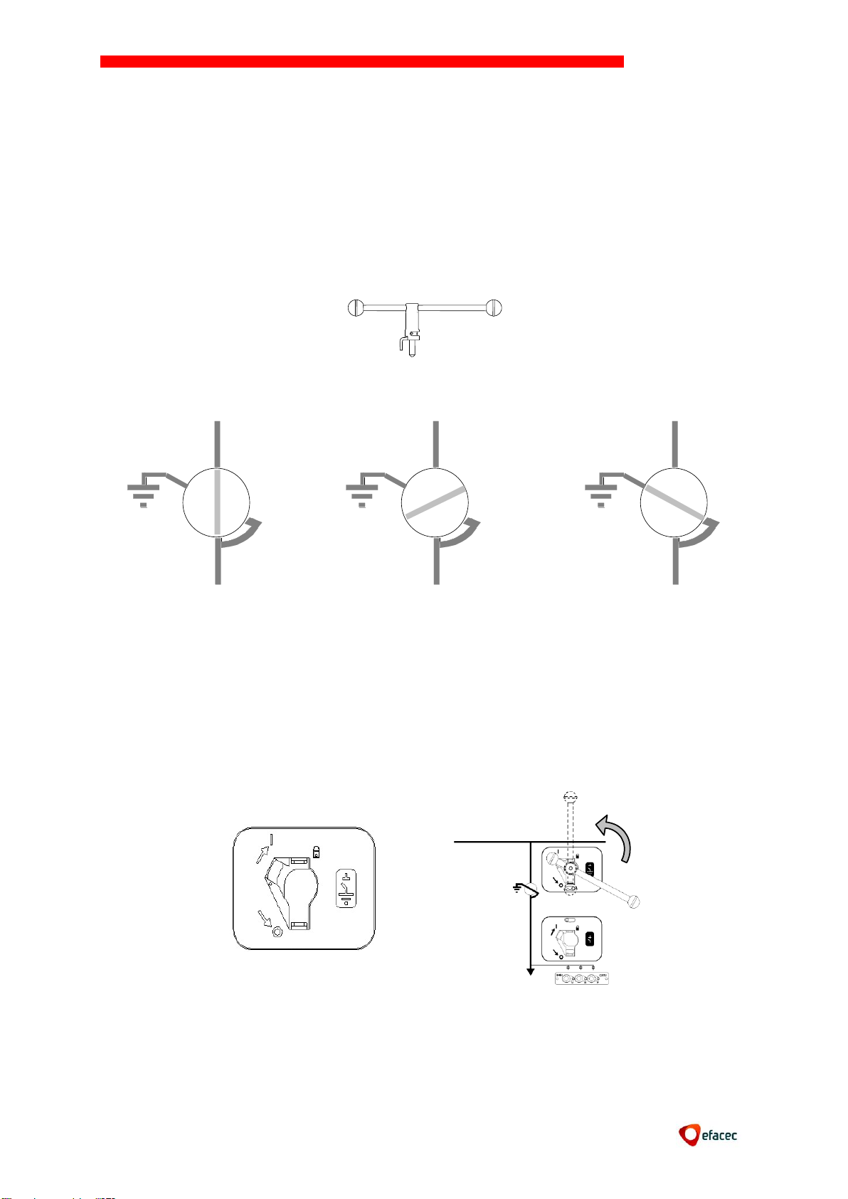
Switch closed
Earthing switch open
Switch opened
Earthing switch opened
Switch opened
Earth switch closed
10. EXPLOITATION
10.1. Operating mechanism operation
The cubicles are shipped with switch disconnector in the open position and earth switch in
closed position.
All maneuvers are made without great efforts.
The motorization is not operational if the maneuver lever is placed.
The mechanism is operated using an operating lever backstop, which function is to prevent
that it goes directly to the switch open position after making the closing maneuver.
10.2. Earth Switch opening operation (CI1 and CI2)
This maneuver is possible only if the earthing switch is closed.
Insert the lever into the slot of the earthing switch maneuver.
Rotate the lever counter-clockwise to the "open" position.
This action will jam the front cable panel and release the position of the open switch.
Page 24
NORMAFIX
23
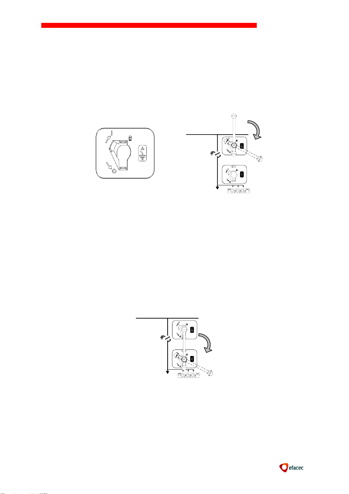
10.3. Earth Switch closing operation (CI1 and CI2)
This maneuver is only possible if the switch is in open position
Insert the lever into the slot of the earthing switch maneuver.
Check that the cables do not have voltage (indicator of the presence of voltage)
Close the earthing switch, moving the lever to the final position, steering it
clockwise
This maneuver:
Closes the Earth switch;
Unlocks the cable access front panel;
Interlocks the Switch in the opened position (it cannot be closed).
10.4. Switch closing operation (CI1 or CS1)
This maneuver is possible only if the earthing switch is in the "open" position
Insert the lever into the slot of the maneuver switch.
Operate the lever clockwise until the final position - the switch closes abruptly.
The command of the earthing switch is stuck in the "open" position.
Page 25
NORMAFIX
24
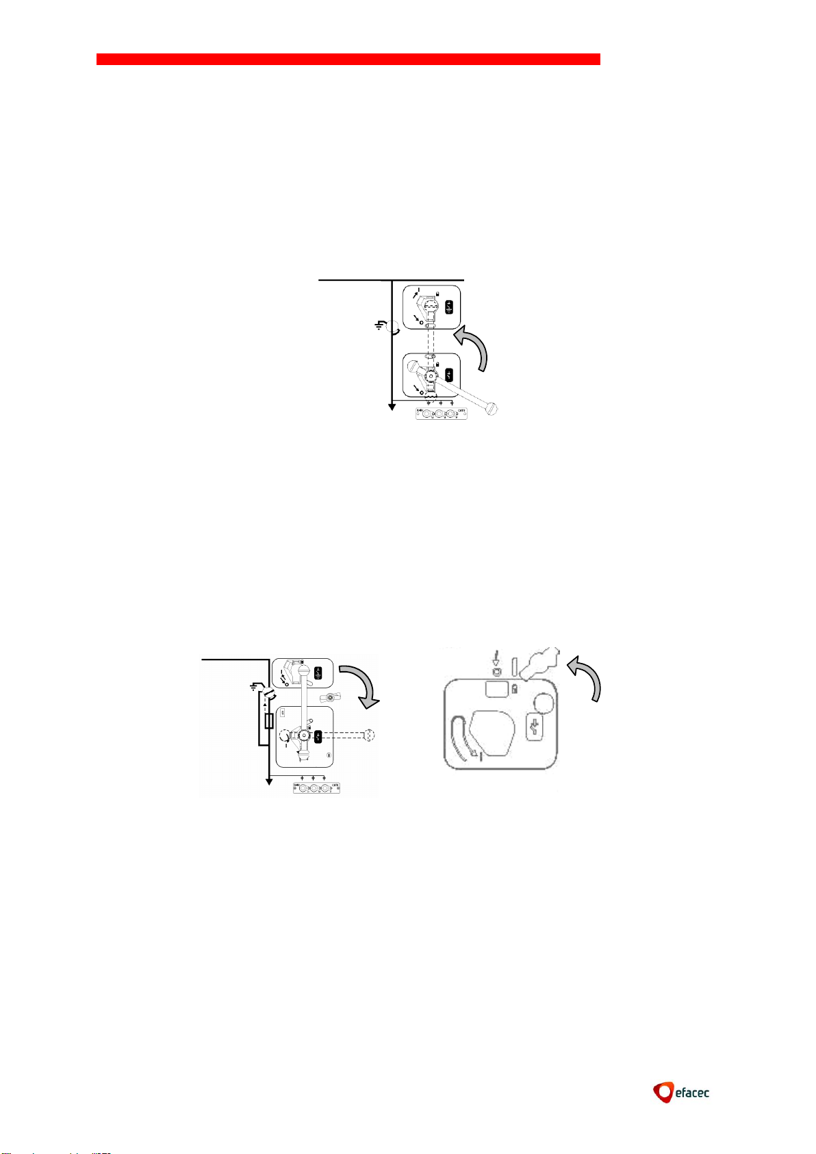
10.5. Switch opening operation (CI1 or CS1)
This maneuver is only possible if the switch is in the closed position;
Insert the lever into the slot of the Switch maneuver;
Operate the lever counter clockwise to the “open” position – the switch opens up
shaply;
The earth switch mechanism is then cleared and can be closed.
10.6. Switch closing operation and recharge for opening (CI2 - transformer protection
function)
This maneuver possible only if the earth switch is in the open position;
Insert the lever into the slot fo the Switch maneuver;
Operate the lever clockwise until the final position;
The Switch closes and the lever remains captive.
Attention, essential maneuver following the closure of the ISF:
Operate imperatively the handle, clockwise, in order to recharge the spring. After
completing this action the handle may be removed and the Switch is now ready to be
opened.
Page 26
NORMAFIX
25
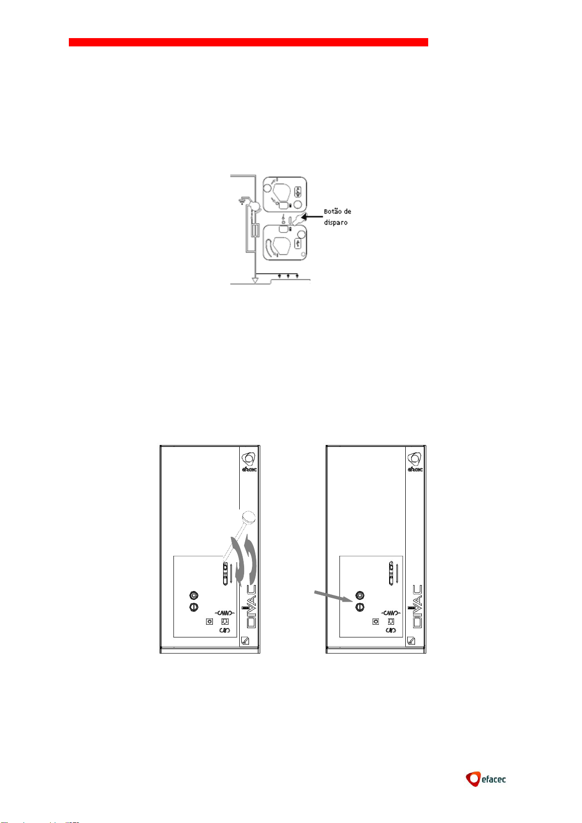
10.7. Switch opening operation (CI2 - transformer protection function)
The opening operation can be made:
Manually (shutter release button in the mechanism)
By a coil opening (optional)
By fuses (fuses mechanical action)
10.8. Closing and opening operations (Vacuum Circuit Breaker, CDV mechanism)
Use the lever to load the springs (execute vertical movements)
Close the circuit breaker by pressing the close button
The circuit breaker will be ready to make an opening maneuver (by pressing the
release button feeded by the release coil)
If you want to make a new maneuver, it is necessary to recharge the springs again,
even if the circuit breaker is not open. If the circuit breaker has a powered
mechanism, it will charge the springs automatically when necessary.
Page 27
NORMAFIX
26
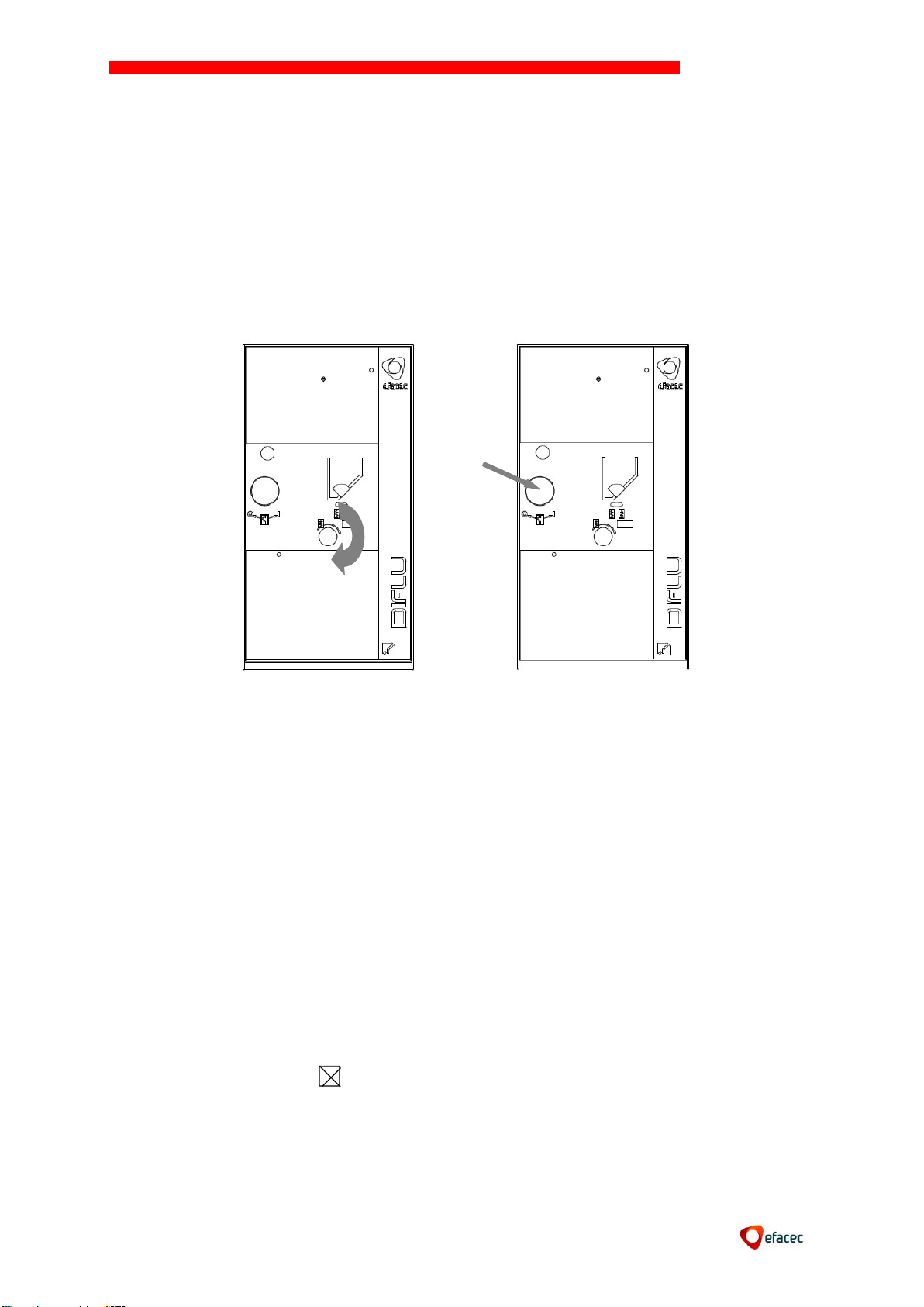
10.9. Closing and opening operations (SF6 Circuit Breaker, CLR mechanism)
Use the lever to load the springs (operate clockwise circular movements).
Close the circuit breaker by turning the maneuver button in a counter-clockwise
direction.
The circuit breaker will be ready to make an opening maneuver (turning the
maneuver button clockwise or by discharging the opening coil).
If you want to make a new maneuver, it is necessary to recharge the springs again,
even if the circuit breaker is not open. If the circuit breaker has a powered
mechanism, it will charge the springs automatically when necessary.
11. MAINTENANCE
NORMAFIX is a maintenance-free product.
However, when the switchgear is inoperative for a long time or if it is under severe
environmental conditions (dust, humidity, salty etc), it is advisable to perform the
following operations whenever there is a duty break:
Visual inspection to confirm the good condition of the material;
Wipe the dust or dirt that may arise in insulators parts (insulators, switches,
transformers, etc.) with a dry cloth. Never use solvents;
Verify the correct operation of the mechanisms and interlocks;
Verify the correct placement of the cable connectors;
Check the tightness of all connections;
Apply a very light coat of neutral industrial vaseline (Mobil Special with MoS2) in
the male contacts of earthing switch and the electrical contacts in air, having
removed the old grease with the help of a cloth impregnated with oil or other non-
chlorinated solvent.
Page 28
NORMAFIX
27
Connection
12. REPLACEMENT
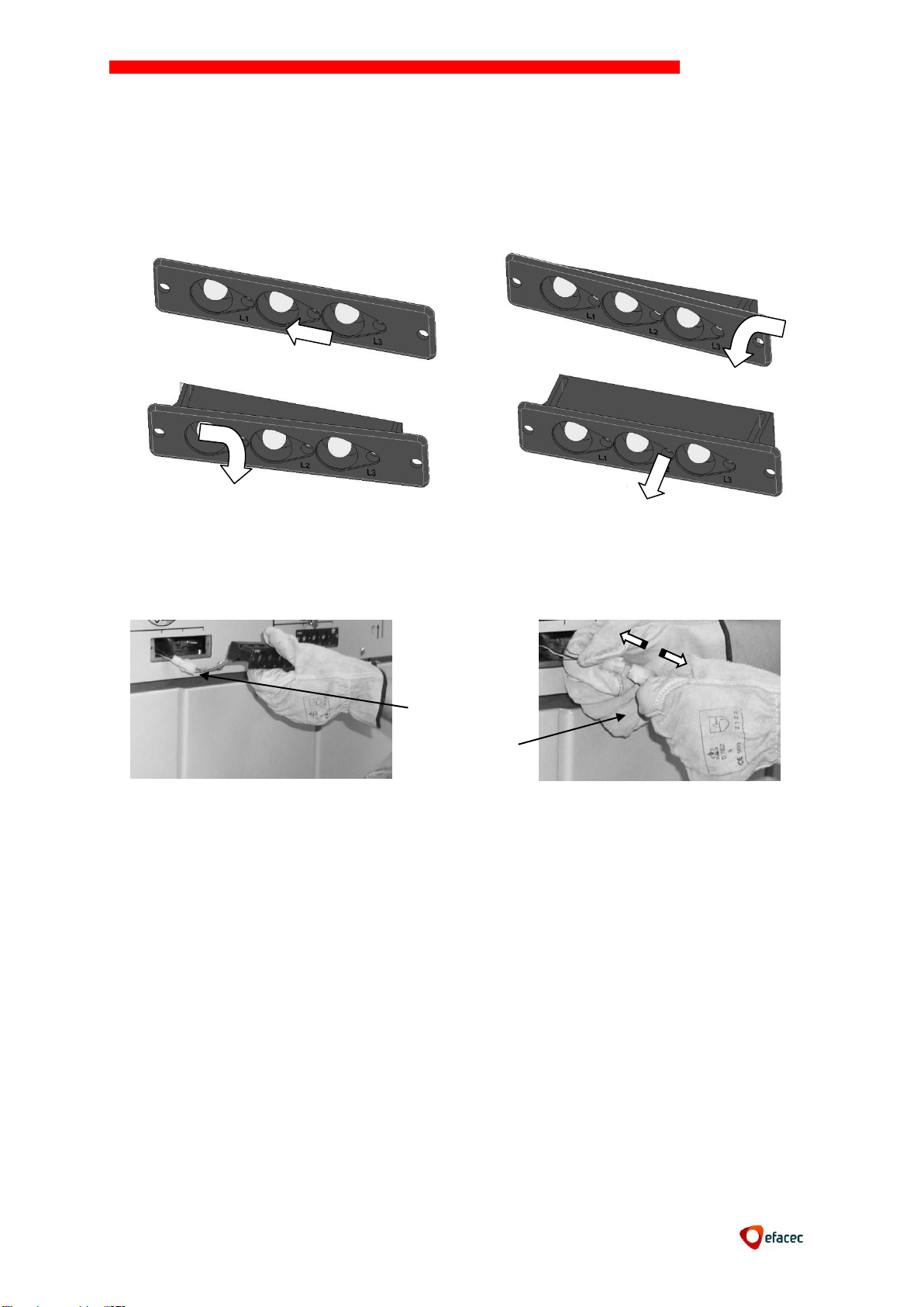
12.1 Replacing the Voltage Signalization lamps
To replace the voltage signalization lamps, proceed as presented in the following pictures.
No tools are required.
After removing the voltage signalization, disconnect the connection.
Connect the voltage signalization again and put it back in its place.
If the unit is energized, the indicator will light up immediately.
12.2 Fuse replacement
To replace the fuses follow the instructions in Chapter 8.10 “Assembling of fuses”.
It is recommended to replace all three fuses.
Page 29
NORMAFIX
28
Front
crossbar
Upper
connections
Bottom
connections
Support
Earth plait
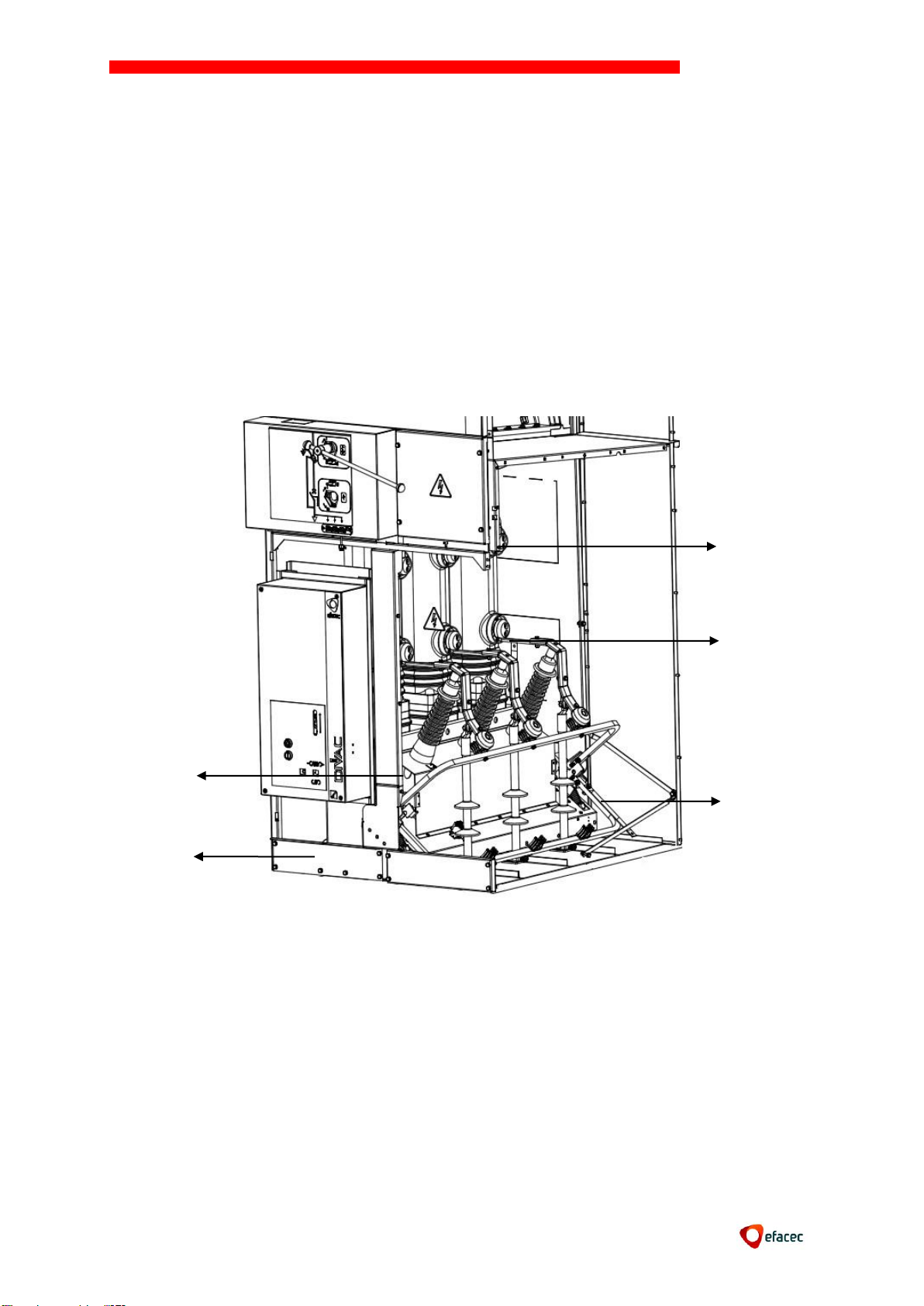
12.3 Removing the automatic switch disconnector of the cubicle
To access the cable compartment it is necessary: to open the breaker, then open the
isolator, and finally close the earthing switch.
Open the cable compartment access panel
Remove the front crossbar (2 screws, wrench 13)
Disconnect the earth braid of circuit breaker (1 screw, wrench 13)
Disconnect the superior and inferior pole connections (12 screws, wrench 13)
Disconnect LV Cabling (Disconnect the low voltage connector and cabling that are
connected to terminals)
Remove the circuit breaker support on the inside of the cubicle
The Circuit breaker is now ready to be removed from the low voltage cabling (with
low voltage connector)
Page 30
NORMAFIX
29
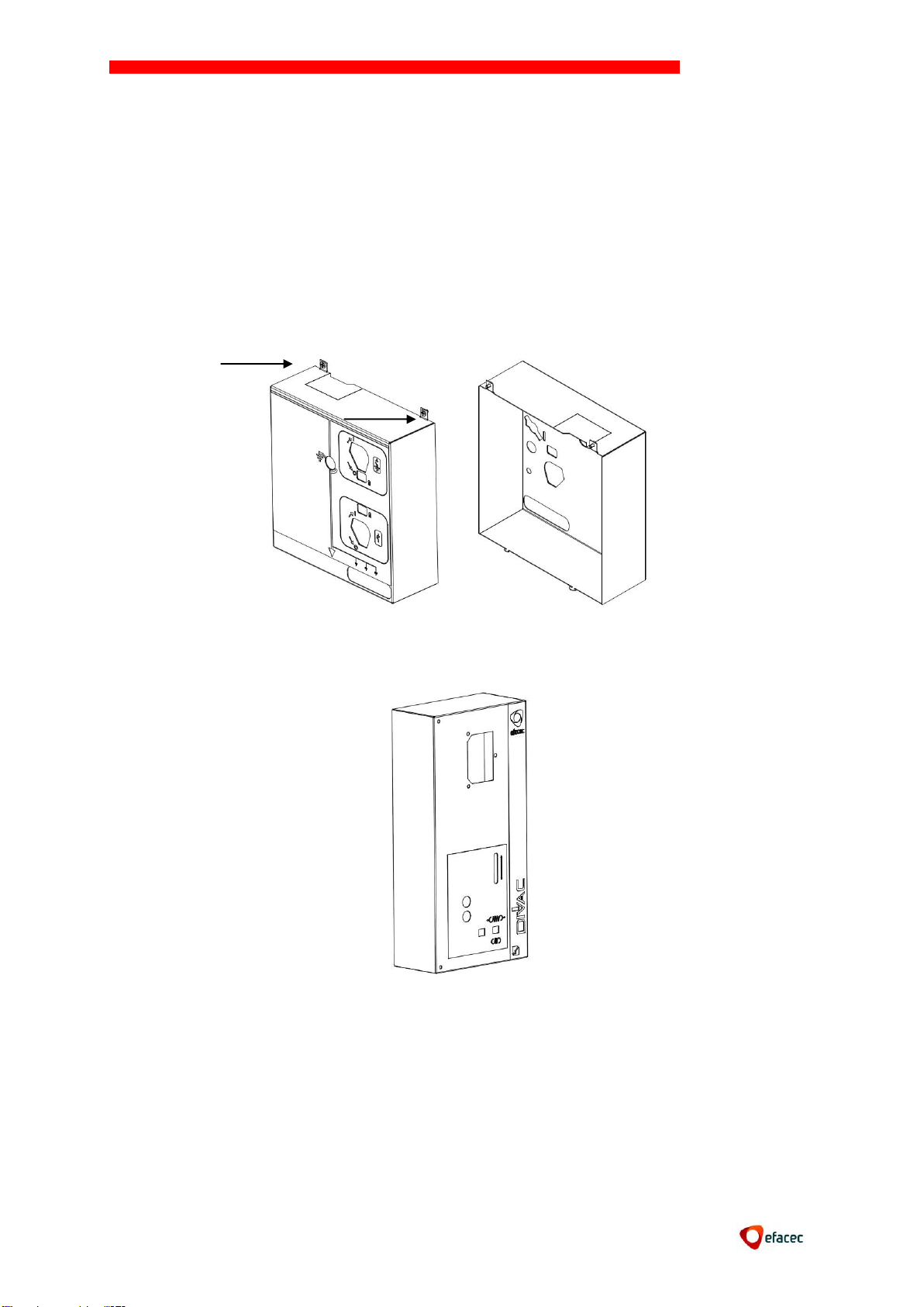
12.4 Removing cover mechanism
All the mechanisms replacement operations should be carried out by the EFACEC´s After
Sales Support Team.
To access the operating switch disconnector or earth switch it is necessary to remove its
cover.
Remove the Low Voltage compartment panel (to have access to the screws and the
cover)
Remove the 2 M6 screws
Undock cover
To access to the operating circuit-breaker it is necessary to remove its cover.
Remove the 2 screws
Undock cover
13. SPARE PARTS
Following are the recommended spare parts:
Lamps for voltage indicator
Fuses (if applicable)
Opening coil (if applicable)
Page 31

AFTER SALES SERVICE
Porto
Arroteia Leça do Bailio Apartado 1018
4466-952 S.Mamede de Infesta Portugal
Tel.: (+351) 22 9562850/2615
Mobile: 96 83 29 61
Fax: (+351) 22 956 28 89
Porto
Arroteia Leça do Bailio Apartado 1018
4466-952 S.Mamede de Infesta Portugal
Telef: (+351) 22 956 23 00
Fax: (+351) 22 956 28 70
Exportation
Arroteia Leça do Bailio Apartado 1018
4466-952 S.Mamede de Infesta Portugal
Telef: (+351) 22 956 23 00
Fax: (+351) 22 952 09 00
Lisboa
Rua da Garagem, 1 Apartado 527 Carnaxide
2796-853 Linda-a-Velha Portugal
Telef: (+351) 21 416 36 00
Fax: (+351) 21 416 36 20
 Loading...