


Betriebsanleitung/ Operating instructions
Wartungsanleitung/ Maintenance instructions
Ersatzteilliste/ Sparepart list
EFA Z 13
Hörnerguillotine
Horn Guillotine
EFA Z 13
Wichtige Informationen:
Diese Anleitung unbedingt dem Bedienpersonal aushändigen!
Important Informations:
Please forward these operating instructions to your operating
personnel!
Schmid & Wezel
D 75433 Maulbronn
Ausführung/ Version
04.2012

INHALTSVERZEICHNIS/ CONTENT
Inhaltsverzeichnis/ Content
1. Verwendung, Lieferumfang, Zubehör....................................................................................4
1.1 Symbole in dieser Anleitung .........................................................................................................4
1.2 Bestimmungsgemäße Verwendung ...............................................................................................4
1.3 Lieferumfang ..............................................................................................................................5
1.4 Zubehör .....................................................................................................................................5
2. Sicherheitshinweise...............................................................................................................5
2.1 Allgemeine Sicherheitshinweise ....................................................................................................5
2.2 Verhalten am Arbeitsplatz ............................................................................................................5
3. Inbetriebnahme und Betriebssicherheit................................................................................5
3.1 Erstinbetriebnahme .....................................................................................................................6
3.2 Schalterbetätigung ......................................................................................................................7
3.3 Arbeiten mit der Zange................................................................................................................8
4. Montage.................................................................................................................................8
4.1 Messerwechsel............................................................................................................................8
4.2 Ventilwechsel..............................................................................................................................9
4.3 Kolbenwechsel ............................................................................................................................9
4.4 Hydraulikaggregat.......................................................................................................................9
4.5 Einstellung des Federzuges ..........................................................................................................9
5. Instandhaltung ....................................................................................................................10
6. Reinigung und Wartung.......................................................................................................11
6.1 Tägliche Reinigung nach Beendigung der Schlachtungen..............................................................11
6.2 Tägliche Wartung der Zange ......................................................................................................12
6.3 Monatliche Wartung ..................................................................................................................12
6.4 Reparatur durch den Kundendienst.............................................................................................12
7. Transport und Lagerung ......................................................................................................13
8. Rücknahme ..........................................................................................................................13
ENGLISH
1. Operation, Scope of Supply, Accessories............................................................................15
1.1 Symbols in this Manual ..............................................................................................................15
1.2 Intended Use ............................................................................................................................15
1.3 Scope of Supply ........................................................................................................................16
1.4 Accessories...............................................................................................................................16
2. Safety precautions...............................................................................................................16
2.1 General safety precautions.........................................................................................................16
2.2 Behaviour at the place of work ...................................................................................................16
3. Commissioning and
operational safety....................................................................................................................16
3.1 Initial operation ........................................................................................................................17
3.2 Switch operation .......................................................................................................................18
3.3 Working with the guillotine ........................................................................................................19
4. Assembly..............................................................................................................................19
4.1 Blade changing .........................................................................................................................19
4.2 Valve replacement.....................................................................................................................20
4.3 Piston changing ........................................................................................................................20
4.4 Hydraulic power pack ................................................................................................................20
4.5 Adjustment of the springbalancer ...............................................................................................20
5. Maintenance ........................................................................................................................21
Schmid & Wezel
D 75433 Maulbronn
Seite/ Page
2/ 33
3
Ausführung/ Version
04.2012

6. Cleaning and maintenance ..................................................................................................22
6.1 Daily cleaning after completion of the slaughters .........................................................................22
6.2 Daily maintenance of the guillotine.............................................................................................23
6.3 Monthly maintenance ................................................................................................................23
6.4 Repair by After-Sales Service .....................................................................................................23
7. Transport and storage .........................................................................................................23
8. End of life provisions ...........................................................................................................24
A. Anhang / Annex...................................................................................................................25
A.1 Technische Daten / Technical Data.............................................................................................25
A.2 Hydraulik- und Pneumatikschema / Hydraulic and pneumatic circuit diagram.................................26
A.3 Gerätegrößen / Machine sizes ....................................................................................................26
A.4 Liste der Ersatz- und Verschleißteile / List of spare and wear parts ...............................................28
A.5 Explosionszeichnung / Exploded view ........................................................................................31
B. Konformitätserklärung / Declaration of Conformity ...........................................................33
Schmid & Wezel
D 75433 Maulbronn
Seite/ Page
3/ 33
3
Ausführung/ Version
04.2012

1. Verwendung, Lieferumfang,
1.2 Bestimmungsgemäße
Zubehör
Hinweise, unbedingt lesen!
Diese Anleitung richtet sich an den Maschinenbediener. Bewahren Sie sie gut auf!
Die Zangen dürfen nur betrieben werden:
in technisch einwandfreiem Zustand bestim-
mungsgemäß sowie sicherheits- und gefahrenbewusst
mit allen angebauten Sicherheitseinrichtungen
gemäß den Sicherheitshinweisen
nachdem das Bedienpersonal diese Anleitung,
insbesondere Kapitel 2 "Sicherheitshinweise" (S.
5) und Kapitel 3 "Inbetriebnahme und Betriebssicherheit" (S. 5) gelesen und verstanden hat
Nur so können Fehlbedienungen vermieden und Gefahrensituationen richtig eingeschätzt werden.
Greifen Sie niemals in den Schneidbereich der Zange, Sie könnten sich sonst Gliedmaßen
abtrennen!
Tragen Sie beim Arbeiten einen
Augenschutz bzw. eine Schutzbrille!
1.1 Symbole in dieser Anleitung
Gefahrensymbol:
Hier ist äußerste Vorsicht und Umsicht
geboten. Bei Fehlverhalten besteht direkte Verletzungsgefahr für das Bedienpersonal oder Dritte. Zudem kann
die Maschine Schaden nehmen.
Informationssymbol:
Mit diesem Symbol versehene Textpassagen geben Ihnen wichtige Informationen und nützliche Tipps.
Verwendung
Die Zangen dienen zum Abtrennen von Hörnern.
Die Zange ist geeignet für den Einsatz in Mittel- und
Großbetrieben.
Die Maschinen sind für eine andere Nutzung nicht
ausgerüstet. Sollte eine anderweitige Nutzung vom
Bediener gewünscht sein, bitte unbedingt vorher
Rücksprache mit der Firma Schmid & Wezel GmbH
& Co. (S&W) halten.
Bei allen anderen Anwendungen muss auf Unfallgefahr bzw. erhöhten Verschleiß hingewiesen werden.
Bei Zuwiderhandlung haftet allein der Benutzer.
1.2.1 Restgefahren
Beim industriellen Einsatz der Zangen an
Tierkörpern besteht die Möglichkeit sich zu verletzen bzw. bei grobem Missbrauch jemanden zu
töten. Da bei bestimmungsgemäßer Verwendung
die Öffnungsgröße zwischen den Zangenmessern
nicht verkleinert werden kann, besteht die Gefahr,
den Hals bzw. den Oberarm oder auch das Schultergelenk zwischen die Zangenmesser zu bringen
und die Zange dann auszulösen. Somit ist bei missbräuchlichem Umgang mit der Möglichkeit des direkten Todes bzw. des Todes durch Verbluten zu
rechnen. Deswegen muss immer auf den richtigen
Umgang mit der Maschine geachtet werden.
Zur Krafterzeugung benötigt die Zange ein Hydraulikaggregat, für die 2-Handbedienung eine pneumatische Steuereinheit.
Die Maschine selbst kann keinen Druck aufbauen.
Der Druckaufbau erfolgt erst in Zusammenwirkung
mit dem vorgeschalteten Druckerzeugungsgerät
und den zugehörigen Schläuchen. Die Maschine darf
erst in Betrieb genommen werden, wenn alle Anforderungen der Druckgeräterichtlinien hinsichtlich
dieses Produktes übereinstimmen.
Die Maschine ist für einen Druck von 200 bar ausgelegt. Für das Druckvolumen in den Zangen sowie im
Druckerzeuger und den Zuleitungen kann ein Wert
pV 240>⋅
von angenommen werden. Für diese
Geräte gilt üblicherweise die Druckgeräterichtlinie
97/23/EG mit entsprechenden Diagrammen. Auf
Grund der soliden Auslegung hinsichtlich Festigkeit,
Formsteifigkeit und Stabilität gegenüber statischen
wie dynamischen Betriebsbeanspruchungen verweisen wir jedoch auf Artikel 1.3.10 der Druckgeräterichtlinie 97/23/EG:
Da der Druck keinen wesentlichen Faktor für die
Konstruktion darstellt, unterliegen die Zangen nicht
der o.g. Richtlinie.
Schmid & Wezel
D 75433 Maulbronn
Seite/ Page
4/ 33
Ausführung/ Version
04.2012

1.3 Lieferumfang
Zange
Betriebsanleitung
1.4 Zubehör
Die Bestellnummern sowohl für im Lieferumfang enthaltene Teile wie für Zubehör finden Sie in Anhang
A.3 "Gerätegrößen / Machine sizes" (S. 26).
2. Sicherheitshinweise
2.1 Allgemeine Sicherheitshinweise
Befolgen Sie beim Gebrauch der Zange
unbedingt nachfolgende Sicherheitsmaßnahmen.
Der Messerwechsel sowie Installations-, War-
tungs- und Reparaturarbeiten dürfen nur bei
vom Aggregat getrennten Geräten durchgeführt werden!
Wahl der persönlichen Schutzausrüstung
entsprechend der betrieblichen Vorgaben und
den geltenden Sicherheits-Richtlinien.
für die Bedienung wird vorausgesetzt, dass das
Bedienpersonal ausreichende Kenntnisse im
Arbeiten mit Zangen hat!
Einweisung muss durch unser Fachpersonal
erfolgen!
Installations-, Wartungs- und Reparaturarbe-
iten dürfen nur von autorisiertem Fachpersonal
durchgeführt werden.
Zangen von S&W entsprechen den einschlä-
gigen Sicherheitsbestimmungen.
Die Zangen sind mit einer Zweihandsicherheitss-
chaltung ausgerüstet. Die beiden Schalter müssen gleichzeitig innerhalb 0,3 Sekunden betätigt
werden.
2.2 Verhalten am Arbeitsplatz
1. Halten Sie Ihren Arbeitsplatz in Ordnung. Unordnung kann Unfälle zur Folge haben.
2. Berücksichtigen Sie Umgebungseinflüsse. Sorgen Sie für gute Beleuchtung (min. 500 Lux).
3. Halten Sie andere Personen von Ihrem Arbeitsplatz fern. Arbeiten Sie konzentriert und mit
Vernunft. Benutzen Sie die Zange nicht, wenn
Sie unkonzentriert und/ oder müde sind.
4. Bewahren Sie die Zange sicher auf. Unbenutzte
Geräte an einem trockenen Ort aufbewahren.
5. Arbeitskleidung: Tragen Sie keine weite Kleindung oder Schmuck - diese können von beweglichen Teilen erfasst werden. Tragen Sie beim
Arbeiten festes Schuhwerk. Tragen Sie generell
ein Haarnetz!
6. Vermeiden Sie eine nicht normale Körperhaltung. Sorgen Sie für sicheren Stand und halten
Sie jederzeit das Gleichgewicht.
7. Pflegen Sie Ihre Werkzeuge mit Sorgfalt. Verwenden Sie nur scharfe und unbeschädigte
Messer, damit Sie besser und sicherer Arbeiten
können.
8. Verwenden Sie nur EFA-Originalmesser. Befolgen Sie die unter Messerwechsel aufgeführten
Vorschriften. Siehe auch Kapitel 4.1.1
"Auswechseln der Messer" (S. 8).
9. Lassen Sie keine Werkzeugschlüssel stecken.
Überprüfen Sie vor dem Einschalten, ob alle
Schlüssel entfernt sind.
10.Verwenden Sie nur EFA-Originalzubehör. Bei
Missachtung erlischt die Gewährleistung. Ein
Gebrauch anderer Einsatzwerkzeuge oder Zubehöre kann die Verletzungsgefahr erhöhen.
11.Veränderungen und Umbauten an der Maschine
sind nicht zulässig und entbinden S&W von jeglicher Gewährleistung und Haftung.
3. Inbetriebnahme und Betrieb-
ssicherheit
Arbeitsplatz
Der Arbeitsbereich für den Bediener sollte mindestens 1,5 qm groß sein. In diesen Bereich sollte
kein anderer Arbeitsplatz hineinragen, da sonst auf
Grund der Bewegungen mit der Zange Verletzungsgefahren entstehen könnten. .
Die Beleuchtung des Arbeitsplatzes muss min. 500
Lux entsprechen.
Stromanschluss
Das Aggregat kpl. muss durch einen anerkannten
Elektrotechniker angeschlossen werden. Vor dem
Einsatz sind die Betriebsdaten von Betriebsnetz und
Gerät auf Übereinstimmung zu prüfen.
Das Aggregat kann nur in der auf
dem Typenschild angegebenen
Spannung betrieben werden.
Keine Umschaltung möglich!
Schmid & Wezel
D 75433 Maulbronn
Seite/ Page
5/ 33
Ausführung/ Version
04.2012

3.1 Erstinbetriebnahme
Die Zange nur ausgeschaltet an
das Betriebsnetz anschließen!
Wesentliche Informationen, z. B.
technische Datenblätter, Zeichnungen
und Stücklisten finden Sie in Anhang
A (S. 25).
3.1.1 Federzug
Die Maschine muss immer
in Kombination mit einer
Gewichtsentlastung (Federzug) betrieben werden.
Bringen Sie den Federzug
mit einer Schiebelaufkatze
an einem höher gelegenen
Element über dem Arbeitplatz oder an der Decke
an.
Informationen zur Feinabstimmung des Federzuges
finden Sie unter Kapitel 4.5 "Einstellung des Federzuges" (S. 9).
Die Zange möglichst kopflastig aufhängen. Die
Senkrechte kann bei Bedarf nach justiert werden.
Aufgrund des Gewichts von ca.
31 kg kann es beim Befestigen
oder Lösen der Gewichtsentlastung zu einer Gefährdung durch
Abrutschen oder Herunterfallen
der Maschine kommen. Achten
Sie auch darauf, dass sich die
Maschine weder am Karabinerhaken noch am Haken der Zange
verklemmt.
Arbeiten Sie umsichtig!
Wenn die Zange nicht benutzt wird, ist diese so abzulegen, dass es nicht zu unbeabsichtigtem Kontakt
mit den Schneiden kommen kann, denn diese sind
scharf.
3.1.2 Druckluftwartungseinheit
Bei fehlerhaftem Druckluftanschluss und einem hohen Wasseranteil in der Druckluft besteht die Möglichkeit, dass Wasser am Anschlusspunkt austritt.
Deshalb ist auf korrekten Schlauchanschluss und
auf Druckluft mit geringem Wasseranteil zu achten
(Wasserabscheider regelmäßig entleeren).
Der Wasserabscheider ist nicht Bestandteil der
Maschine, sondern muss vorgeschaltet werden.
Abbildung 1:
Federzug
Eine Wartungseinheit ist an dem Hydraulikaggregat
montiert (Durchflusspfeil auf Wartungseinheit
beachten).
Ein Wasserabsorber ist, sofern keine getrocknete
Luft vorhanden ist, kundenseitig vorzusehen.
Ölfüllung : Öl (001365611/12) verwenden
Ölereinstellung: bei ca. 15 Schnitten 1 Tropfen Öl.
Manometereinstellung: Betriebsdruck 6-8 bar.
3.1.3 Hydraulikaggregat
Der Schneidmechanismus der Zange funktioniert
hydraulisch. Schließen Sie die Zange an ein betriebsbereites Hydraulikaggregat an (siehe hierzu
auch separate Betriebsanleitung für das Hydraulikaggregat), dazu
geben Sie feingefiltertes Hydrauliköl
(001365614) in die vorgesehene Einfüllöffnung
(ca. Füllvolumen 50l) und
schließen das Aggregat über Klemmkasten (Y-
Schaltung 3: 400 V ~, 50 Hz) an.
Die zu verwendenden Hydraulikschläuche haben
unterschiedlich große Gewindeanschlüsse und können daher nicht falsch angeschlossen werden.
Anschluss Hydraulikschläuche
Hydraulikschläuche Vorlauf M16 x 1,5 und Rück-
lauf M14 x 1,5 mit den Gewindeanschlüssen am
Hydraulikaggregat und mit den schraubbaren
Hydraulikkupplungen an der Zange anschließen.
Die Kupplungen fest bis in Endlage schrauben,
da sie in gelockerter Verbindung selbstsperrend
sind.
Entlüftung der Zange ist nicht erforderlich, da
nach mehrmaligem Betätigen der Zange die Luft
über die Hydraulikschläuche aus dem Aggregat
entweicht.
Steuerschlaucheinheit (59-68) mit 2 Sechskant-
schrauben (64) an Zange anschrauben.
Anschluss Steuerleitung an Zange: Leitung (66)
an Verteiler (2) anschließen. Lage des
Anschlusses beachten.
Die mehradrige Leitung (66) durch die untere
Öffnung des Gehäuses der pneumatischen
Steuerung schieben (Hydraulikaggregat).
Für die pneumatische Steuerung werden nur 3
Leitungen benötigt. Die Farblose Leitung bleibt
leer.
Die Rote Leitung in Schnellsteckanschluss „a"
und gelbe Leitung in Schnellsteckanschluss „b"
des Zweihand-Sicherheitsblockes bis zum
Anschlag einschieben.
Blaue Leitung in Schnellsteckanschluß „Pl" des Y
- Anschlusses bis zum Anschlag einschieben.
Schmid & Wezel
D 75433 Maulbronn
Seite/ Page
6/ 33
Ausführung/ Version
04.2012

Druckluftanschluß mittels Druckluftschlauch (NW. 6 mm) an Außengewindetülle anschließen. Druckbereich
5-8 bar. Keinen Öler dazwischen montieren.
Druckschalter
ZweihandSicherheitsblock
Druckluft P= 5-8 bar
Schlauchnippel
Wartungseinheit
Einschraubanschluss
Wegeschieber
Druckschaltgerät
Abbildung 2: Anschlussplan für EFA Zangen (Anschluss Aggregat 001972301, 001972302)
Detail
Anschlag
O-Ring
Haltezahn-Spannzange
Plastikschlauch
Anschluss des Plastikschlauchs:
Schlauch bis Anschlag einschieben
Lösen des Plastikschlauchs:
Mit Schraubenzieher auf Außenring
der Spannzange drücken und
Schlauch herausziehen
3.1.4 An- und Abkuppeln der Zange
An- und Abkuppeln der Zange in
drucklosem Zustand!
Aggregat mit Ha
uptschalter kpl. ausschalten
und Schalter T1 und T2 an den Griffen (35)
gleichzeitig ca. 3 - 4 mal betätigen. Dadurch
wird der Wegeschieber geschaltet und der unter
Druck stehende Rücklauf- Hydraulikschlauch
(68,69) drucklos ( siehe Hydraulik- und Pneumatikplan).
Danach Druckluft abschalten.
Jetzt können beide Hydraulikschläuche (68 +
74) sowie die Steuerschlaucheinheit (59-66)
abgeschraubt werden.
Die Hydraulikkupplungen sind selbstsperrend, so
dass beim Abkuppeln kein Öl ausläuft.
Sie sollten Kupplung und Steckerteile
vor Verschmutzung schützen!
3.2 Schalterbetätigung
Erst nach vorherigem Lesen dieser Bedienungsanleitung und
nach korrektem Anschluss darf
die Zange eingeschaltet werden!
Die Zange ist mit einer Zweihand-Sicherungsschaltung ausgerüstet.
3.2.1 Einschalten
Zange sicher halten!
Abbildung 3: Schalter, Handgriff
Schmid & Wezel
D 75433 Maulbronn
Beide Schaltergriffe zeitgleich betätigen, um die
Seite/ Page
7/33
Messer zu schließen (Abb. 3)
Ausführung/ Version
04.2012

3.2.2 Ausschalten
Schaltgriffe loslassen, um Messer zu öffnen
Der Schneidvorgang kann jederzeit abgebrochen
oder wiederholt werden.
3.3 Arbeiten mit der Zange
Greifen Sie niemals in den Schneidbereich der Zange, Sie könnten sich sonst Gliedmaßen
abtrennen!
Bei Werkzeugwechsel die Zange
vom Druckluftnetz trennen.
Tragen Sie beim Arbeiten einen
Augenschutz bzw. eine Schutzbrille!
Tragen Sie beim Arbeiten einen
Gehörschutz!
3.3.2 Betriebssicherheit
Maschine an beiden Handgriffen sicher halten
beim Zerlegen besonders umsichtig handeln.
Die Schneiden schließen innerhalb von 3,0 s
stets rechtwinklig und im Schneidebereich
ansetzen, damit es nicht zu einem Messerbruch
durch Überlastung kommt.
zur sichereren Handhabung (Führung) die
Zange an einem Federzug aufgehängen
4. Montage
Vor allen Montagearbeiten das
Gerät vom Betriebsnetz trennen!
Zange drucklos vom Netz trennen:
Aggregat ausschalten. Zange an beiden Griffen
halten und ausschalten, dann loslassen. Druckschläuche sind danach entlastet.
Die zur Montage notwendigen Zeichnungen finden
Sie in Anhang A.5 "Explosionszeichnung / Exploded
view" (S. 31).
3.3.1 Arbeitgang
Hydraulikaggregat muss betriebsbereit sein
Zange sicher halten, richtig ansetzen und Zwei-
hand-Sicherungsschaltung betätigen (siehe
Kapitel 3.2 "Schalterbetätigung" (S. 7))
Zange ansetzen. Schalter gleichzeitig drücken (max.
Zeitdifferenz 0,3 sek +/- 0,1 sek.). Aggregat kpl.
schaltet ein und das bewegliche Messer(12) fährt
vor.
Nach Beendigung des Schneidvorganges beide
Griffschalter loslassen. Das bewegliche Messer geht
in Ausgangsstellung. Ein evtl. Nachschneiden kann
vorgenommen werden, ohne dass die Ausgangsstellung des beweglichen Messers erreicht wurde. Dazu
wieder beide Schaltergleichzeitig drücken..
Die Zange immer rechtwinklig und im
Schneidebereich (nicht mit den Messerspitzen) ansetzen. Ansonsten kann
es in Folge einer Überlastung zum
Messerbruch kommen.
Eine Entlüftung der Zange ist nicht erforderlich, da
nach mehrmaligem Betätigen der Zange die Luft
über die Hydraulikschläuche aus dem Belüftungsfilter des Hydraulikaggregates entweicht.
4.1 Messerwechsel
4.1.1 Auswechseln der Messer
1. Messer (12) zufahren
2. Luftleitung (5 und 6) demontieren
3. 2 Schrauben (17) lösen und entfernen
4. 2 Schrauben (18, 19) lösen
5. 2 Schrauben (9) aus Träger (10) schrauben
6. Träger (10) demontieren
7. Das feststehende Messer (12) kann demontiert
werden
8. 2 Schrauben (4) lösen und bewegliches Messer
(12) nach vorne herausziehen
9. Montage der Messer in umgekehrter Reihenfolge (Pkt. 8-1).
10.Messerspiel der Messer (12) mit Stellschraube
(18) einstellen. Messerspiel soll max. 0,1-0,3
mm betragen (Messer nie fest gegeneinander
fahren - d.h. Messerspiel = 0 mm)
11.Stellschraube (18) mit Mutter (19) kontern.
Vor dem Zusammenbau der Zange die demontierten
Teile reinigen, auf Verschleiß überprüfen und gegebenenfalls austauschen.
Schmid & Wezel
D 75433 Maulbronn
Sämtliche Gleitstellen mit EFA-Spezialfett einfetten.
Seite/ Page
8/ 33
Ausführung/ Version
04.2012

4.1.2 Überprüfung des Messerspieles
Die Messer müssen (wegen Bruchgefahr) immer
spielfrei und leichtgängig eingestellt sein. Die Einstellung erfolgt über die Sechskantmutter (18, 19).
4.1.3 Messermontage
Vor dem Wiedereinbau die demontierten Teile reinigen, auf Verschleiß überprüfen und gegebenenfalls
austauschen. Sämtliche Gleitstellen mit EFA-Spezialfett einfetten.
4.2 Ventilwechsel
Auswechseln der Ventilteile
Schraube (36) demontieren, Handgriff (35) ist
lose
Sicherungsring (32) lösen und Ventil (26 - 31)
abnehmen, Teile reinigen, auf Verschleiß überprüfen und in umgekehrter Reihenfolge montieren.
Das Ventil (26 - 31) zusammen mit Sicherungsring
(32) immer nur komplett austauschen.
12.Kolben (48) demontieren, Stirnlochschlüssel in
stirnseitige Bohrungen des Kolbens einsetzen
und Kolben lösen
13. Fehlerhaften Teile austauschen.
Achtung : Dichtungssatz immer mit Kolbenstange (46) austauschen => sonst ist die Dichtung des Zylinders nicht gewährleistet.
14.Montage in umgekehrter Reihenfolge (Punkt 13
bis 1), Teile (46 und 49) vor der Montage leicht
einölen (auf Verträglichkeit mit Hydrauliköl
achten).
Achtung:
Die Führung (43) und das Zylinderrohr (51) müssen
mit Loctite 542 gesichert sein!
Kolben (48) nur mit Montagekegel und
Spreizhülse montieren - Demontage nur durch
Erwärmen auf 150 °C möglich.
Zylinderrohr in Führung (43) eingeschraubt und
mit Loctite 542 gesichert.
Verschraubung (40, 52) mit Teflonband mon-
tieren
4.3 Kolbenwechsel
Auswechseln der Kolbenteile
1. Druckschlauch von Z13 abkuppeln
2. Zwei Abdeckbleche (8) demontieren
3. Zwei Schrauben (4) und zwei Schrauben (9 von
Träger 10) demontieren
4. Zwei Messer (12) und Träger (10) nach vorne
ziehen und demontieren
5. Flansch (13 ) mit Schlagschrauber aus Führung
(43) herausschrauben und demontieren
6. Vier Zylinderschrauben (37) für Führung (43)
ausschrauben
7. Zylinderrohr (51) lösen
8. Demontage:
Führung (43) einspannen und Zylinderrohr (51)
mit Hakenschlüssel losdrehen. Ggf. zuvor die
beiden Verschraubungen (38-40 und 52-58)
losschrauben. Achtung Leckölauslauf!
9. Zylinderrohr (51) abziehen und Einzelzeile (44-
50) auf Kolbenstange (46) montiert ausbauen.
Buchse (44) gelegentlich prüfen (kaum Versch-
leiß)
Sämtliche Gleitstellen und Messer (12) mit EFA-Spezielafett einfetten (s. Kapitel 6.1.3 "Schmiermittel
und Hydrauliköl" (S. 12).
4.4 Hydraulikaggregat
Wenigstens einmal im Jahr Ölfüllung ablassen,auf
Verschmutzung kontrollieren und eventuell ersetzen. (Siehe hierzu Anhang 3.1.3 "Hydraulikaggregat" (S. 6) und separate Betriebsanleitung für
das Hydraulikaggregat).
4.5 Einstellung des Federzuges
Die Feinabstimmung des Federzuges erfolgt über
die PLUS/MINUS-Schraube an seinem Gehäuse (siehe Abb. 4).
10.Oberfläche der Kolbenstange (46) prüfen, Oberfläche darf nicht beschädigt sein, bei
beschädigter Oberfläche Kolbenstange austauschen gegen Neuteil sonst weiter mit Punkt.
11.
11.Kolbenstange (46) einspannen. Auf Oberfläche
achten, sie darf nicht beschädigt werden.
Schmid & Wezel
D 75433 Maulbronn
Seite/ Page
Abbildung 4: Federzug
drehen Sie dazu die Schraube in Richtung
MINUS bis sich das Gerät frei schwebend im
Gleichgewicht (mit der Zugfeder) auf Arbeitshöhe befindet
Ausführung/ Version
9/ 33
04.2012

Sollte kein Auszug möglich sein, ist der Federzug
blockiert und eine Neueinstellung ist notwendig:
drehen Sie die Schraube in Richtung PLUS bis
ein Auszug möglich wird und beginnen Sie
erneut mit der Feineinstellung (siehe oben)
Tabelle 1: Fehler- und Störungsliste
Störung mögliche Ursache Behebung
5. Instandhaltung
Während des Betriebes kann die Funktion gestört
sein, die Fehlerbehebung ist in den meisten Fällen
aber relativ einfach. In Tabelle 1: "Fehler- und
Störungsliste" sind diese Störungen mit möglichen
Ursachen und resultierenden Behebungsmöglichkeiten aufgeführt.
Bei Betätigung der Schalthebel
läuft weder die Pumpe noch
schließt die Zange
Bei Betätigung der Schalthebel
läuft die Pumpe an,
dennoch schließt Zange nicht
1. Aggregat nicht eingeschaltet Aggregat einschalten
2. Stromversorgung nicht richtig
3. Druckluftversorgung an Zange
/Aggregat nicht angeschlossen
4. zu geringer Luftdruck für
Schaltung
5. Steuerleitung defekt
6. Zweihand-Sicherungsblock
defekt
7. Kupplungsstecker des
Hydraulikrücklaufschlauches
nicht korrekt angezogen
8. Kolbenbruch (46)
9. defekte Dichtungen
Stromversorgung prüfen und
Fehler beheben
Prüfen und ggf. anschließen
Luftdruck am Aggregat auf mind.
5 bar bei 5 m Schlauchlänge
Steuerleitung prüfen und austauschen
Sicherungsblock prüfen und austauschen
korrekter Anschluss des
Schlauches
Kolben ausbauen und prüfen, ggf
austauschen s. Kapitel 4.3 "Kolbenwechsel" (S. 9)
Dichtungen prüfen und austauschen
Bei Betätigen des Schalthebel
läuft die Pumpe an, aber die
Zange schließt langsam
Hydraulikpumpe zu heiß
Pumpe läuft, jedoch kein Hydraulikdruck in der Zange
Schmid & Wezel
D 75433 Maulbronn
10. Ölstand zu gering
11. Ölfilter an Pumpe verschmutzt
12. Schlauchkupplung lose
13. Zahnradpumpe defekt Zahnradpumpe austauschen
14. Ölfilter an Pumpe verschmutzt
15. Zahnradpumpe defekt Zahnradpumpe austauschen
16. Dichtungen im Hydraulikzylinder sind defekt
Seite/ Page
10/ 33
Öl nachfüllen (Kapitel 3.1.3
"Hydraulikaggregat" (S. 6))
Ölfilter und Öl wechseln
korrekten Anschluss der
Schläuche überprüfen
Ölfilter und Öl wechseln
Dichtungen austauschen
Ausführung/ Version
04.2012

Tabelle 1: Fehler- und Störungsliste
Handgriff lässt sich nicht drücken
Beim Loslassen des Handgriffs
öffnet Zange nicht
Pumpe läuft nicht
Bewegliches Messer hat in der
Aufnahme zu viel Spiel
Keine Schnittleistung
17. Ventil defekt
18. Ventil durch Verschmutzung
blockiert
19. siehe unter Punkt 10 siehe unter Punkt 10
20. Ventilbolzen verklemmt,
geht nicht in Ausgangsposition
zurück oder Ventilfeder ist gebrochen
21. Einstellung des Zeitventils im
Aggregat falsch
22. siehe separate Betriebsanleitung für Pumpe
23. Führungsleiste (1 und 16)
eingelaufen
24. Messerschneide ist stumpf Messer demontieren und schärfen
25. Messerspiel zu groß
Ventil austauschen (siehe Kapitel
4.2 "Ventilwechsel" (S. 9)"
Ventil reinigen (siehe Kapitel 4.2
"Ventilwechsel" (S. 9)"
Ventil reinigen oder austauschen
(siehe Kapitel 4.2 "Ventilwechsel"
(S. 9)"
Einstellung korrigieren
(siehe separate Betriebsanleitungen für Aggregat)
siehe separate Betriebsanleitung
für Pumpe
Führungsleiste austauschen
mit Schraube/Mutter (18 und 19)
neu einstellen
Messerspiel 0,1-0,3mm
6. Reinigung und Wartung
Vor allen Reinigungs- und Wartungsarbeiten das Gerät vom
Betriebsnetz trennen!
6.1 Tägliche Reinigung nach Beendi-
gung der Schlachtungen
Ein störungsfreier Dauerbetrieb ist nur dann
gewährleistet, wenn die Zange ständig hygienisch
einwandfrei sauber gehalten wird. Üblicherweise
sollte das Gerät vor jeder Reinigung desinfiziert werden.
Beachten Sie dazu die geltenden Sicherheits- und
Hygieneanforderungen (DIN EN 1672)!
Desinfektionsmittel dürfen weder direkt noch indirekt mit Lebensmitteln in Berührung kommen.
Spülen Sie das Gerät daher nach der Desinfektion
mit klarem Wasser ab.
Keine scharfen Lösungsmittel
zusetzen! Keinen Dampf- bzw.
Hochdruckstrahler verwenden!
Gerät nicht in Wasser tauchen!
6.1.1 Desinfektion
Das Gerät während des Betriebes nach jedem
Schnitt mit heißem Wasser (82 °C) desinfizieren.
6.1.2 Reinigung der Zange
Zur Reinigung das Gerät nach den Arbeitseinsatz
mit Lappen, Bürste und warmen Wasser (40 - 55°C)
reinigen. Hartnäckige oder verkrustete Verschmutzungen müssen eingeweicht werden. Reinigen Sie
dazu mit einem Reinigungsmittel, wenn möglich als
Schaum, das Sie auf die zu reinigende Fläche
verteilen und 15 - 20 min. einwirken lassen. Anschließend gelösten Schmutz mit warmen Wasser
manuell abwaschen.
Empfohlene Reinigungsmittel
Diversey Lever Tego 2000: Oberflächenaktives
Desinfektionsmittel
Diversey Lever GmbH
Mallaufstr. 50-56, 68219 Mannheim
P3-topax 91: Oberflächenaktives Desinfektions-
mittel
Henkel-Ecolab Deutschland GmbH
Postfach 13 04 06, 40554 Düsseldorf
Einen Reinigungsplan und weitere Einzelheiten erhalten Sie unter o.g. Adressen.
Die o.g. Reinigungsmittel sind nur eine Empfehlung;
bei Verwendung von anderen Reinigungsmitteln
Schmid & Wezel
D 75433 Maulbronn
Seite/ Page
11/33
Ausführung/ Version
04.2012

müssen Materialverträglichkeit sowie Hygienevorschriften kundenseitig geprüft werden.
6.1.3 Schmiermittel und Hydrauliköl
Das Schmiermittel sowie das Hydrauliköl unterliegen den im Lebensmittelbereich notwendigen Vorschriften (DIN 1672).
Empfohlenes Schmierfett
Klübersynth UH1 14-222 (1 kg Spezialfett in Dose)
Qualität: Zulassung H1
Best.-Nr. 001 365 621
Wartungseinheit
Säurefreies Markenöl (001 365 612/11) mit einer
Viskosität von 3-4 E/20°C, Anilinpunkt 60°C.
Ölereinstellung: bei ca. 15 Schnitten l Tropfen Öl.
Empfohlenes Hydrauliköl
Shell Risella D15 (ISO VG 10 - ISO VG 68 nach DIN
51519)
Qualität: ohne Zulassung H1:
Bestell-Nr 001 365 614
Qualität mit Zulassung H1:
Bestell-Nr.: 001 365 647
6.2 Tägliche Wartung der Zange
Zange nach Einsatz reinigen und Messer (12) leicht
einölen.
6.2.1 Schmierung
Nach jeder Reinigung die Gleitstellen sowie die
Messer mit EFA-Spezielfett ( 001 365 621) leicht einfetten.
6.3 Monatliche Wartung
ACHTUNG!
Auf Sauberkeit achten! Einfülltrichter mit feinmaschigem Sieb verwenden (Maschenweite ca. 0,4
mm).
Wenigstens einmal im Jahr Ölfüllung ablassen, auf
Verschmutzung kontrollieren und eventuell ersetzen.
Das Hydrauliköl ist als gefahrbringender Stoff klassifiziert und muss
entsprechend gebraucht und entsorgt
werden. Hydrauliköl darf keinesfalls in
die Kanalisation oder ins Freie gelangen.
6.3.4 Schärfen der Messer
Nicht richtig geschärfte Messer bringen Produktionseinbußen bzw. erhebliche Gefährdung für den Benutzer.
Wir haben für Sie in unserer ServiceAbteilung einen Schärfdienst
eingerichtet. Bitte wenden Sie sich in
diesem Fall an die nächstgelegene
Vertragswerkstatt oder direkt an unser Stammhaus.
Bei fachgerechtem Einsatz ist ein Nachschärfen der
Messer (12) meist nicht erforderlich.
Gegebenenfalls können die Messer bei geringer Materialabnahme auch mit handelsüblichen Schleifgeräten nachgeschärft werden.
Keine Gewalt anwenden, da Teile
beschädigt werden könnten!
Verwenden Sie ausschließlich
EFA-Originalersatzteile!
6.3.1 Führungsleistenspiel
Regelmäßig das Führungsleistenspiel (1, 12, 16)
überprüfen. Wegen Bruchgefahr müssen die Messer
immer leichtgängig und spielfrei eingestellt sein.
6.3.2 Wartungseinheit
Die Wartungseinheit ist in regelmäßigen Abständen
zu überprüfen, das Kondenswasser zu entfernen
und das Spezialöl (001 365 612) nachzufüllen.
6.3.3 Hydraulikaggregat
Den Ölstand regelmäßig kontrollieren und gegebenenfalls Öl nachfüllen. Siehe auch Kapitel 3.1.3
"Hydraulikaggregat" (S. 6) und gesonderte Betriebsanleitung für Hydraulikaggregat.
Schmid & Wezel
D 75433 Maulbronn
Seite/ Page
6.4 Reparatur durch den Kundendienst
Vor allen Reparaturarbeiten das
Gerät vom Hydrauliknetz trennen!
Reparaturen dürfen nur von Fachkräften
vorgenommen werden.
Für Reparaturen steht Ihnen unsere Servicea-
bteilung zur Verfügung. Bitte wenden Sie sich im
Falle einer Reparatur an die nächstgelegene
Vertragswerkstatt oder direkt an unser Stammhaus.
Ausführung/ Version
12/ 33
04.2012

Auf Wunsch können für die Reparaturwerkstatt
mit Fachkräften Ersatzteillisten nachgereicht
werden.
Nach Reparaturen müssen die Getriebe jedes
Mal erneut dauergeschmiert werden!
7. Transport und Lagerung
Die Maschine muss in einem trockenen, gelüfteten
Raum gelagert werden.
Die Maschine ist nach Kapitel 6.1.2 "Reinigung der
Zange" (S. 11) zu reinigen und in trockenem Zustand zu transportieren.
Es ist darauf zu achten, dass die Maschine beim
Transport nicht beschädigt wird.
8. Rücknahme
Geben Sie Altgeräte zum Entsorgen an das Stammhaus zurück.
Schmid & Wezel
D 75433 Maulbronn
Seite/ Page
13/ 33
Ausführung/ Version
04.2012

ENGLISH
Schmid & Wezel
D 75433 Maulbronn
Seite/ Page
14/ 33
14
Ausführung/ Version
04.2012

1. Operation, Scope of Supply,
1.2 Intended Use
Accessories
Notes, read carefully!
This manual is intended for the machine operator.
Keep it in a safe place!
The guillotines may only be operated:
In a technically safe condition, for its intended
use and in accordance with the applicable safety
and accident prevention regulations
With all the safety devices attached
In accordance with the safety precautions
When the operating personnel has read and
understood this manual, in particular Chapter 2
"Safety precautions" (p. 16) and Chapter 3
"Commissioning and operational safety" (p. 16)
Only in this way can incorrect operation be avoided
and hazard situations correctly assessed.
Never reach into the cutting area
of the guillotine to avoid the risk
of cutting off limbs!
The guillotines serve for cutting off horns.
The guillotine is suitable for use in medium-sized
and large slaughterhouses.
The machines are not equipped for any other form
of use. Should the operator wish to use the guillotine in some other way, please consult Schmid &
Wezel GmbH & Co. (S&W) beforehand.
Use in any other way may result in a risk of accidents and increased wear to the guillotine. The user
alone bears the liability for the consequences of any
other form of use.
1.2.1 Residual risks
During industrial use of the guillotines on animal
carcasses there is a risk of injuring yourself or, in the
case of gross negligence, of killing someone. Since
during the intended use, the size of the opening between the guillotine knives cannot be reduced,
there is a risk of the neck or upper arm or even the
shoulder joint coming between the guillotine knives
and the guillotine then being closed. Improper use
of the guillotine could thus lead to instant death or
to death by bleeding. . Be sure therefore to always
use the machine in the proper manner.
Wear eye protection or safety
goggles when working with the
guillotine!
1.1 Symbols in this Manual
Hazard symbol:
The greatest care and attention must
be taken here. Lack of attention can
result in an immediate risk of injury for
the operating personnel or third parties. Furthermore, the machine may
be damaged.
Information symbol:
Texts marked with this symbol contain important information and useful
tips.
The guillotine requires a hydraulic power pack to
generate the cutting force, for 2-hand operation
also a pneumatic control unit.
The machine itself cannot build up any pressure.
The pressure is only built up in conjunction with the
upline pressure generator and the corresponding
hoses. The machine may only be put into operation
when all the requirements of the Pressure Vessel Directive applicable to this product have been observed.
The machine is designed for a pressure of 200 bar.
A value of can be assumed for the
pressure volume in the guillotines and in the pressure generator and hoses. The Pressure Vessel Directive 97/23/EC with the corresponding diagrams
generally applies to these elements. In view of the
sturdy design with respect to strength, torsional rigidity and stability under static and dynamic operating loads, however, we would refer you to Article
1.3.10 of the Pressure Vessel Directive 97/23/EC:
As the pressure constitutes no significant factor for
the design, the guillotines are not subject to the provisions of the above Directive.
pV 240>⋅
Schmid & Wezel
D 75433 Maulbronn
Seite/ Page
15/ 33
Ausführung/ Version
04.2012

1.3 Scope of Supply
Guillotine
Operating manual
1.4 Accessories
The order numbers for both the parts contained in
the scope of supply and for accessories can be
found in Annex A.3 "Gerätegrößen / Machine sizes"
(p. 26).
2. Safety precautions
2.1 General safety precautions
Be sure to observe the following safety precautions when working with the guillotine.
Changing the blades as well as installation,
maintenance and repair work may only be carried out when the machine is disconnected from
the power pack!
Select personal protection equipment according
to the regulations applicable on the premises
and to the accident prevention regulations in
force.
It is assumed that the operating personnel is
sufficiently familiar with the use of guillotines!
The operators must be instructed by our special-
ist personnel!
Installation, maintenance and repair work may
only be carried out by authorised and qualified
personnel
Guillotines from S&W comply with the relevant
safety regulations
The guillotines are equipped with a two-hand
safety circuit. The two switches have to be
pressed simultaneously (within 0.3 seconds).
2.2 Behaviour at the place of work
5. Work clothing: Do not wear loose clothing or
jewellery as these could become tangled up in
moving parts. Wear solid shoes when working.
Wear a hair net as a general rule!
6. Avoid abnormal body postures. Ensure a safe
working position and keep your balance at all
times.
7. Service your tools with care. Use only sharp and
undamaged blades so that you can work better
and safer.
8. Use only original EFA blades. Follow the instructions given under "Changing the blades". See
also Chapter 4.1.1 "Changing the blades" (p.
19).
9. Do not leave wrenches on the machine. Check
that all wrenches have been removed before
starting the machine.
10.Use only original EFA accessories. Use of other
accessories will void the warranty. Use of other
tools or accessories may increase the risk of
injury.
11.Modifications and changes to the machine are
not permitted and will relieve S&W of any warranty and liability.
3. Commissioning and
operational safety
Place of work
The working area for the operator should be at
least 15 square feet. No other place of work should
extend into this area, as the movements with the
guillotine could result in the risk of injury. .
The illumination at the place of work must be at
least 500 lux.
Connection to the power supply
The complete unit must be connected by a qualified
electrician. Before putting the guillotine into operation, check the ratings of the power supply network
and of the guillotine for correspondence.
1. Keep your place of work tidy. Untidiness can
lead to accidents.
2. Give consideration to environmental influences.
Ensure good lighting (min. 500 lux).
3. Keep other people away from your place of
work. Work in a concentrated and sensible manner. Do not use the guillotine when you are
unconcentrated and/or tired.
4. Store the guillotine in a safe place. Store the
guillotine in a dry place when not in use.
Schmid & Wezel
D 75433 Maulbronn
Seite/ Page
16/ 33
The machine can only be operated at the voltage indicated on
the rating plate. No switch-over
possible!
Ausführung/ Version
04.2012

3.1 Initial operation
Important information, e.g. technical
data sheets, drawings and parts lists
can be found in Annex A (p. 25).
Connect the guillotine to the
works network only when it has
been switched off!
3.1.1 Spring balancer
The machine must always
be operated in combination
with a weight relief system
(spring balancer).
Install the spring balancer
with a trolley to a higher
element above the place of
work or to the ceiling.
Figure 1:
Spring balancer
Information on fine adjustment of the spring balancer can be found in Chapter 4.5 "Adjustment of
the spring balancer" (p. 20).
Suspend the guillotine so that it is as top-heavy as
possible. The vertical position can be adjusted, if
necessary.
In view of the weight of approx.
31 kg, there is a danger of the
machine slipping or falling when
attaching or releasing the weight
relief system. Pay attention also
that the machine does not jam on
the trigger snap or on the hook of
the guillotine.
Work cautiously!
When the guillotine is not in use, store it so that
there is no risk of accidental contact with the blades
as they are sharp.
3.1.2 Air conditioner
If the compressed air connection is not made correctly and with a high water content in the compressed air, there is a possibility of water escaping
at the connection point. Therefore pay attention to
correct connection of the hose and to a low water
content in the compressed air (empty the water trap
at regular intervals).
The water trap does not form part of the machine
and has to be installed upline of the machine.
An air conditioner is installed on the hydraulic power
pack (observe the flow direction arrow on the conditioner).
If no dried compressed air is available, a water absorber has to be provided by the customer.
Oil filling : Use oil (001365611/12)
Oiler setting: 1 drop of oil every approx. 15 cuts
Pressure gauge setting: Working pressure 6-8 bar.
3.1.3 Hydraulic power pack
The cutting mechanism of the guillotine functions
hydraulically. Connect the guillotine to an operational hydraulic power pack (see also the separate operating manual for the hydraulic power pack), by
pouring finely filtered hydraulic oil (001365614)
into the filler opening provided (approx. filling
volume 50 l) and
connecting the power pack to the terminal box
(Y-circuit 3: 400 V ~, 50 Hz).
The hydraulic hoses to be used have threaded fittings of different sizes and therefore cannot be connected incorrectly.
Connection of hydraulic hoses
Connect the hydraulic hoses inlet M16 x 1.5 and
return M14 x 1.5 with the threaded fittings to
the hydraulic power pack and with the threaded
hydraulic couplings to the guillotine.
Screw the couplings firmly into their end position and they are self-locking when loose.
Venting of the guillotine is not necessary, as the
air escapes from the power pack via the hydraulic hoses after a few actuations.
Screw the control hose unit (59-68) with 2 hex-
agon head bolts (64) to the guillotine.
Connection of control line to guillotine: Connect
line (66) to distributor (2). Observe the position
of the connection.
Push the multi-core lead (66) through the lower
opening of the housing of the pneumatic controller (hydraulic power pack).
Only 3 cores are required for the pneumatic
controller. The colourless core is not connected.
Completely push the red lead into quick-coupler
"a" and the yellow lead into quick-coupler "b" of
the two-hand safety block.
Completely push the blue lead into quick-cou-
pler "Pl" of the Y-connection.
Connect the compressed air supply with a com-
pressed air hose (NW. 6 mm) to the fitting with
the outside thread. Working pressure range 5-8
bar. Do not install an oiler in between.
Schmid & Wezel
D 75433 Maulbronn
Seite/ Page
17/ 33
Ausführung/ Version
04.2012

Figure 2: Connection diagram for EFA guillotine (connection of unit 001972301, 001972302)
Two-hand
safety block
Compressed air P = 5-8 bar
Hose nipple
Air conditioner
Screw-in
Directional control valve
Pressure switch
port
Stop
O-ring
Toothed retainer
Plastic hose
Connection of the plastic hose:
Push in the hose completely
Releasing of the plastic hose:
Press with a screwdriver onto the
outer ring of the retainer and
pull out the hose
Detail
3.1.4 Connecting and disconnecting the guil-
lotine
Turn off the machine at the main switch and
press switches T1 and T2 on the handles (35)
simultaneously approx. 3 - 4 times. This actuates the directional control valves and depressurises the pressurised hydraulic return hose
(68,69) (see hydraulic and pneumatic circuit
diagram).
Then switch off the compressed air supply.
The two hydraulic hoses (68 + 74) and the con-
trol hose unit (59-66) can now be unscrewed.
The hydraulic couplers are self-locking so that no oil
escapes when they are disconnected.
Connecting and disconnecting the
guillotine in pressure-free state!
Protect the coupling and plug parts
against soiling!
3.2 Switch operation
The guillotine may only be
switched on after reading this
operating manual and correct
connection to the power supply!
The guillotine is equipped with a two-hand safety
circuit.
3.2.1 Switching on
Hold the guillotine firmly!
Figure 3: Switches, handle
Schmid & Wezel
D 75433 Maulbronn
Actuate both switches simultaneously to close
Seite/ Page
18/33
the blades (Fig. 3)
Ausführung/ Version
04.2012

3.2.2 Switching off
Release the switches to open the blades
The cutting process can be interrupted or repeated
at any time.
3.3 Working with the guillotine
Wear ear protectors during work!
Never reach into the cutting area
of the guillotine to avoid the risk
of cutting off limbs!
During tool changing, disconnect
the guillotine from the compressed air network.
Wear eye protection or safety
goggles when working with the
guillotine!
3.3.1 Working process
The hydraulic power pack must be ready for
operation.
Hold the guillotine firmly, position correctly and
actuate the two-hand safety circuit (see Chapter
3.2 "Switch operation" (p. 18))
Position the guillotine. Press the switches simultaneously (max. time difference 0.3 sec +/- 0.1 sec.).
The complete unit switches on and the moving
blade (12) moves forwards.
After completing the cut, release both handle
switches. The moving blade returns to its starting
position. After after-cutting can be performed without waiting for the moving blade to return to its
starting position. To do this, press both switches simultaneously again.
Always apply the guillotine at right angles and in the cutting area (not with
the blade tips). Otherwise the blades
may break due to overload.
Venting of the guillotine is not necessary, as the air
escapes from the venting filter of the hydraulic power pack via the hydraulic hoses after a few actuations of the guillotine.
3.3.2 Work safety
Hold the machine firmly with both handles.
Work particularly carefully when breaking. The
blades closes within 3.0 s
Always apply the guillotine at right angles and in
the cutting area in order to avoid blade breakage due to overload.
Suspend the guillotine from a spring balances
for safe handling (guidance).
4. Assembly
Disconnect the machine from the
works mains before starting any
assembly work!
Depressurise the guillotine before disconnect-
ing from the mains supply:
Switch off the machine. Hold the guillotine with
both handles and switch off, then release. The
pressure hoses are depressurised.
The drawings necessary for assembly can be found
in Annex A.5 "Explosionszeichnung / Exploded view"
(p. 31).
4.1 Blade changing
4.1.1 Changing the blades
1. Close the blades (12)
2. Disconnect the air hoses (5 and 6)
3. Loosen and remove the 2 screws (17)
4. Loosen the 2 screws (18, 19)
5. Remove the 2 screws (9) from bracket (10)
6. Remove bracket (10)
7. The fixed blade (12) can be removed
8. Loosen the 2 screws (4) and pull out the moving
blade (12) to the front
9. Reassemble the blades in the reverse order
(point 8-1).
10.Adjust the clearance of the blades (12) with
adjusting screw (18). The blade clearance
should be max. 0.1-0.3 mm (never run the
blades against one another - i.e. blade clearance
always > 0 mm)
11.Lock adjusting screw (18) with nut (19).
Before assembling the guillotine, clean the removed
parts, inspect for wear and replace, if necessary.
Schmid & Wezel
D 75433 Maulbronn
Grease all sliding points with EFA Special Grease.
Seite/ Page
19/ 33
Ausführung/ Version
04.2012

4.1.2 Checking the blade clearance
In order to avoid breakage, the blades must always
be adjusted without clearance but with free movement. Adjustment is made with hex. nuts (18, 19).
4.1.3 Blade installation
Before reassembling the guillotine, clean the removed parts, inspect for wear and replace, if necessary. Grease all sliding points with EFA Special
Grease.
4.2 Valve replacement
Replacing the valve parts
Remove screw (36) to release handle (35).
Remove snap ring (32) and pull out valve (26 -
31), clean the removed parts, inspect for wear
and install again in the reverse order.
Always replace the valve (26 - 31) together with the
snap ring (32).
4.3 Piston changing
Replacing the piston parts
1. Disconnect the pressure hose from Z13
2. Remove the two sheet covers (8)
3. Remove two screws (4) and two screws (9)
from bracket (10)
4. Pull out the two blades (12) and bracket (10) to
the front to remove
5. Remove flange (13 ) from guide (43) using an
impact wrench
6. Remove the four cylindrical screws (37) of guide
(43)
7. Loosen the cylinder barrel (51)
8. Removal:
Clamp guide (43) and unscrew cylinder barrel
(51) with a hook-type wrench. If necessary, first
remove the two screw fittings (38-40 and 52-
58). Caution! Leak-off oil runs out!
9. Pull of cylinder barrel (51) and remove the individual parts (44-50) installed on piston rod (46).
10.Inspect the surface of the piston rod (46); the
surface must not be damaged. If the surface is
damaged, replace the piston rod with a new
part, otherwise continue at point. 11.
11.Clamp the piston rod (46). Pay attention that
the surface is not damaged.
12.Remove the piston (48); insert the face wrench
into the bores in the face of the piston and
unscrew the piston
13. Replace faulty parts.
Caution: Always replace the seal kit with the
piston rod (46) => otherwise sealing of the cylinder is not assured.
14.Reassemble in the reserve order (points 13 to
1), oil parts (46 and 49) lightly before installation (pay attention to compatibility with the
hydraulic oil).
Caution:
The guide (43) and the cylinder barrel (51) must be
secured with Loctite 542!
Install piston (48) only with mounting cone and
expander sleeve - removal is possible only after
heating to 150° C.
Cylinder barrel screwed into guide (43) and
secured with Loctite 542.
Install screw fitting (40, 52) with Teflon tape
Inspect bushing (44) occasionally (barely sub-
ject to wear)
Grease all sliding points and blades (12) with EFA
Special Grease (see Chapter 6.1.3 "Lubricants and
hydraulic oil" (p. 22).
4.4 Hydraulic power pack
At least once a year, drain the oil filling, inspect for
soiling and replace if necessary. (See also Annex
3.1.3 "Hydraulic power pack" (p. 17) and separate
operating manual for the hydraulic power pack).
4.5 Adjustment of the spring balancer
The fine adjustment of the spring balancer is effected via the PLUS/MINUS screw on its housing (see
Fig. 4).
Figure 4: Spring balancer
Turn the screw towards MINUS until the device
is suspended freely with the spring balancer at
working height
If the guillotine cannot be pulled out, the spring balancer is jammed and a readjustment is necessary:
Turn the screw in PLUS direction until the guillo-
tine can be pulled out and start the fine adjustment again (see above).
Schmid & Wezel
D 75433 Maulbronn
Seite/ Page
20/ 33
Ausführung/ Version
04.2012

5. Maintenance
Malfunctions may occur during operation, but these
are generally relatively simple to remedy. Table 1:
"Troubleshooting" lists these malfunctions with possible causes and resulting potential remedies.
Table 1: Troubleshooting
Malfunction Possible cause Remedy
When the trigger lever is pressed,
the pump does not run and the
guillotine does not close
When the switch lever is pressed
the pump starts,
but the guillotine does not close
1. Power pack not switched on Switch on power pack
2. Electric power supply not correct
3. Compressed air supply not
connected to guillotine / machine
4. Insufficient air pressure for
switching
5. Control line defective
6. Two-hand safety block defective
7. Plug connector of the
hydraulic return hose
not correctly tightened
8. Piston fracture (46)
9. Gaskets defective
Check the electric power supply
and remedy the fault
Check and connect, if necessary
Set the air pressure at the power
pack to at least 5 bar with 5 m
hose length
Inspect the control line and
replace, if necessary
Inspect the safety block and
replace, if necessary
Connect the hose correctly
Remove and inspect the piston,
replace if necessary, see Chapter
4.3 "Piston changing" (p. 20)
Inspect the gaskets and replace,
if necessary
When the trigger lever is pressed,
the pump starts but the guillotine
closes too slowly
Hydraulic pump too hot
Pumps runs, but no hydraulic
pressure in the guillotine
Handle cannot be pressed
Schmid & Wezel
D 75433 Maulbronn
10. Oil level too low
11. Oil filter on the pump clogged Change the oil and oil filter
12. Hose coupling loose
13. Gear pump defective Replace gear pump
14. Oil filter on the pump clogged Change the oil and oil filter
15. Gear pump defective Replace gear pump
16. Gaskets in hydraulic cylinder
defective
17. Valve defective
18. Valve jammed due to soiling
Seite/ Page
21/ 33
Top up oil (Chapter 3.1.3
"Hydraulic power pack" (p. 17))
Check correct connection of the
hoses
Replace gaskets
Replace valve (see also Chapter
4.2 "Valve replacement" (p. 20)"
Clean valve (see also Chapter 4.2
"Valve replacement" (p. 20)"
Ausführung/ Version
04.2012

Table 1: Troubleshooting
19. See under point 10 See under point 10
20. Valve pin jammed,
Guillotine does not open when
handle is released
Pump does not run
Moving blade has too much clearance in the mounting
No cutting performance
does not return to starting position or valve spring is broken
21. Setting of timer valve in
power pack not correct
22. See separate operating
manual for pump
23. Guide ledge (1 and 16) worn Replace guide ledge
24. Knife blade is blunt Remove and sharpen blades
25. Blade clearance too large
6. Cleaning and maintenance
Disconnect the machine from the
works mains before all cleaning
and maintenance work!
Clean or replace valve
(see Chapter 4.2 "Valve replacement" (p. 20)"
Correct setting
(see separate operating manuals
for power pack)
See separate operating manual
for pump
Adjust clearance with screw/nut
(18 and 19)
Blade clearance 0.1-0.3 mm
cleaning agent, preferably as a foam, that is applied
to the surface to be cleaned and allowed to work for
15 - 20 minutes. Subsequently wash off the dissolved soiling manually with warm water.
Recommended cleaning agents
Diversey Lever Tego 2000: Surface-active disin-
fectant
6.1 Daily cleaning after completion
of the slaughters
Continuous reliable operation can only be assured if
the guillotine is kept hygienically clean at all times.
The machine should normally be disinfected before
each cleaning.
Observe the applicable safety and hygiene regulations (DIN EN 1672)!
Disinfectants must not be allowed to come into direct or indirect contact with foodstuffs. Rinse the
machine with clear water after disinfection.
Do not use aggressive solvents!
Do not use steam or high-pressure cleaners! Do not immerse
the machine in water!
6.1.1 Disinfection
Disinfect the machine during operation after every
cut with hot water (82° C).
6.1.2 Cleaning the guillotine
Clean the machine after use with a cloth, brush and
warm water (40 - 55° C). Stubborn or encrusted
soiling must be soaked beforehand. Clean using a
Diversey Lever GmbH
Mallaufstr. 50-56, 68219 Mannheim
P3-topax 91: Surface-active disinfectant
Henkel-Ecolab Deutschland GmbH
Postfach 13 04 06, 40554 Düsseldorf
A cleaning plan and further details can be obtained
from the above addresses.
The above cleaning agents are only a recommendation; if other cleaning agents are used, the customer
should examine the material compatibility and the
compliance with the hygiene regulations.
6.1.3 Lubricants and hydraulic oil
The lubricant and the hydraulic oil have to meet the
regulations for the foodstuffs sector (DIN 1672).
Recommended lubricating grease
Klübersynth UH1 14-222 (1 kg special grease in can)
Grade: Approval H1
Order No.001 365 621
Air conditioner
Acid-free branded oil (001 365 612/11) with a viscosity of 3-4 E/20°C, anilin point 60° C.
Oiler setting: 1 drop of oil every approx. 15 cuts
Schmid & Wezel
D 75433 Maulbronn
Seite/ Page
22/33
Ausführung/ Version
04.2012

Recommended hydraulic oil
Shell Risella D15 (ISO VG 10 - ISO VG 68 to DIN
51519)
Grade: without H1 approval:
Order No.: 001 365 614
Grade with H1 approval:
Order No.: 001 365 647
6.3.4 Sharpening the blades
Incorrectly sharpened blades detract from your productivity and also constitute considerable risks for
the user.
We have set up a sharpening service
for you in our Service department. In
this case, please contact your nearest
contract workshop or our parent company directly.
6.2 Daily maintenance of the
guillotine
Clean the guillotine after use and oil the blades (12)
lightly.
6.2.1 Lubrication
After every cleaning, coat the sliding surfaces and
the blades lightly with EFA special grease ( 001 365
621).
6.3 Monthly maintenance
6.3.1 Guide ledge clearance
Check the guide ledge clearance (1, 12, 16) at regular intervals. In order to avoid breakage, the blades
must always be adjusted without clearance but with
free movement.
6.3.2 Air conditioner
The air conditioner must be inspected at regular intervals, the condensed water drained from the water trap and the special oil (001 365 612) topped up.
6.3.3 Hydraulic power pack
Check the oil level at regular intervals and top up, if
necessary. See also Chapter 3.1.3 "Hydraulic power
pack" (p. 17) and the separate operating manual for
the hydraulic power pack.
CAUTION!
Pay attention to cleanliness! Use a filler funnel with
a fine-mesh screen (mesh width approx. 0.4 mm).
At least once a year, drain the oil filling, inspect for
soiling and replace if necessary.
The hydraulic oil is classified as a hazardous substance and must be used
and disposed of accordingly. On no
account may hydraulic oil drain into
the sewage system or escape into the
atmosphere.
If used correctly, resharpening of the blades (12) is
normally not necessary.
If required, the blades can also be resharpened with
minimum material removal using commercially
available grinders.
Do not use force as parts could be
damaged!
Use only original EFA spare parts!
6.4 Repair by After-Sales Service
Disconnect the machine from the
hydraulic network before starting
any repair work!
Repairs may only be carried out by specialist
personnel.
Our Service department is at your disposal for
all repair work. In the event of a repair, please
contact your nearest contract workshop or our
parent company directly.
On request, spare parts lists can be supplied to
the repair workshop with qualified specialist
staff.
After every repair, the gear units must be
repacked with grease!
7. Transport and storage
The machine must be stored in a dry, well-ventilated
room.
The machine must be cleaned as described in Chapter 6.1.2 "Cleaning the guillotine" (p. 22) and transported in dry condition.
Schmid & Wezel
D 75433 Maulbronn
Ensure that the machine is not damaged during
transport.
Seite/ Page
23/ 33
Ausführung/ Version
04.2012

8. End of life provisions
At the end of their useful service life, return old machines to the parent company for disposal.
Schmid & Wezel
D 75433 Maulbronn
Seite/ Page
24/ 33
Ausführung/ Version
04.2012

A. Anhang / Annex
A.1 Technische Daten / Technical Data
Zange/Cutter EFA Z13
Zangenöffnung / Cutter opening 130 x 160 mm
Schlauchlänge / Hose length 5 m
Gewicht / Weight 31 kg
Schließzeit / Closing time 3,0 s
Schließkraft / Closing force 62,3 kN
Öffnungszeit / Opening time 2,0 s
Federzug / Spring balance 001 620 052
Schalldruckpegel / Sound pressure
level (EN ISO 11688-1)
Hand-Arm Vibration./Hand-arm
vibration (EN 28662)
Elektrisch /
Aggregat / Aggregate
Gewicht / Weight 65 kg 48 kg
Betriebsdruck / Working pressure 200 bar 216 bar
Motorleistung / Motor output 4,0 kW
Spannung und Frequenz /
Voltage and frequency
Stromaufnahme /
Current consumption
Luftverbrauch pro Schnitt /
Air consumption per cut
Drucklufthauptanschluss /
Compressed air main connection
Electric
230V
230V, 50/60 Hz 400V, 50/60 Hz
16,3 A 9,4 A
< 85 dB(A)
< 2,5 m/ s
Elektrisch/
Electric
400V
1,6 cm³
2
Druckluftantrieb/
Pneumatic drive
G 1/2“ , 6 - 8 bar
Ölfüllung (Förderleistung) /
Oil filling (delivery rate)
Anschluss f. pneum. Steuereinheit /
Connection for pneumatic control
unit
Schmid & Wezel
D 75433 Maulbronn
50 l, (12,5 l/min)
Schlauch DN = 7mm, 4 - 8bar
Seite/ Page
25/ 33
32
Ausführung/ Version
04.2012

A.2 Hydraulik- und Pneumatikschema / Hydraulic and pneumatic circuit diagram
Zangengriff/Cutter handle
Druckluft/
5-8 bar
Compressed
air 5-8 bar
Pumpenaggregat/
Pump unit
Abbildung 1: Schaltschema Aggregat / Figure 1: Aggregate circuit diagram
Zange/Cutter
Druckschaltgerät
(hydr.) /
Pressure switch
(hydr.)
Druckschaltgerät
(pneum.)
Pressure switch
Zweihandsicherheitsblock/Two-hand safety block
Wegeschieber/
Directional control valve
Das Aggregat ist in unmittelbarer Nähe zum Arbeitsplatz zu positionieren. / The aggregate must be located in
the immediate vicinity of the place of work.
Druckluftanschluss Netz max. 2m zu Aggregat. / Compressed air main connection max. 2 m from the
aggregate.
A.3 Gerätegrößen / Machine sizes
schlanker Träger
200 DIN 1025 /Lean girder 200 DIN 1025
Schiebelaufkatze /Travelling crab
Federzug / Spring balancer
Anschlussleitung 5 m lang/Connecting lead 5 m long
pneum.
Steuerung/
pneum. control
Abbildung 2: Hörnerguillotine mit Elektroantrieb / Horn guillotine with electric engine
Schmid & Wezel
D 75433 Maulbronn
Seite/ Page
26/ 33
32
Ausführung/ Version
04.2012

Abbildung 3: Hörnerguillotine mit Druckluftantrieb / Horn guillotine with pneumatic engine
Schiebelaufkatze /
Federzug / Spring balancer
schlanker Träger
200 DIN 1025 /Lean girder 200 DIN 1025
Anschlussleitung 5 m lang/ Connecting lead 5 m long
pneum.
Steuerung/
pneum. control
elektr.
Steuerung/
elctr. control
Travelling crab
Schmid & Wezel
D 75433 Maulbronn
Seite/ Page
27/ 33
32
Ausführung/ Version
04.2012

A.4 Liste der Ersatz- und Verschleißteile / List of spare and wear parts
Bild-Nr. Stück Benennung Designation Best.-Nr.
Hörnerguillotine kpl. Horn guillotine compl. 008 009 032
1 1 Führungsleiste Guide ledge 003 009 035
2 1 Verteilerstück Distributor 003 009 039
2a 1 Aufhängung Suspension 003 010 106
2b 2 Schraube Screw 001 325 908
2c 2 Federring Spring washer 001 317 003
3 16 Federring Spring washer 001 317 002
4 4 Sechskantschraube Hexagon screw 001 325 913
5 8 Einschraubanschluss Pipe union 001 610 601
6 1 Flexible Rilsan Leitung Flexible hose 001 610 602
7 10 Sechskantschraube Hexagon screw 001 325 921
8 2 Abdeckblech Sheet cover 003 009 037
9 4 Sechskantschraube Hexagon screw 001 325 931
10 1 Träger Support 007 009 033
11 3 Schelle Clamp 001 371 920
12 4 Büchse Sleeve 003 009 040
13 2 Messer (gewölbt) Blade 003 009 007
14 1 Flansch Flange 003 009 042
15 4 Zylinderstift Cylinder pin 001 307 224
16 1 Träger Support 007 009 034
17 1 Führungsleist
18 1 Sechskantschraube Hexagon screw 001 327 204
19 2 Stellschraube Adjusting screw 002 000 292
20 2 Sechskantmutter Hexagon nut 001 304 620
21 4 Halbrundkerbnagel Half-round groove stud 001 306 502
22 1 Typenschild Type plate 003 009 290
23 2 H
24 4 Federring Spring washer 001 317 003
25 4 Sechskantschraube Hexagon screw 001 325 908
Griff kpl.
(Pos. 26 - 36)
Flansch kpl.
(Pos. 26 - 34)
alter Holder 003 009 038
Handle compl.
(fig. 26 - 36)
Flange compl.
(fig. 26 - 34)
e Guide ledge 003 009 036
008005 278
008 005 277
Z13
Schmid & Wezel
D 75433 Maulbronn
n Valve pin 003 005 063
sert 003 005 055
O-ring 001 312 636
Valve lever 007 005 159
aube Countersunk screw
Seite/ Page
28/ 33
32
001 326 515
Ausführung/ Version
04.2012

Hydraulikzylinder kpl
Hydraulikzylinder kpl.
(Pos. 42-52)
Hydraulic cylinder
(fig. 42-52)
(Pos.42 - 52)
39 1 Kupplungsstecker Coupling plug 001 606 591
40 1 Gerader Einschraubstutzen Connection piece 001 606 598
41 1 Gerader Einschraubstutzen Connection piece 001 607 154
42 1 Abstreif
43 1 Nutring Packing ring 001 964 009
44 1 Führung Guide 001 964 016
45 1 Buchse Sleeve 001 964 008
46 1 Distanzbuchse Spacer 003 009 041
47 1 Kolbenstange Piston rod 001 964 004
48 1 O.Ring O-ring 001 312 659
49 1 Kolben Piston 001 964 002
50 1 Kolbendichtung Piston packing 001 964 010
51 1 O.Ring O-ring 001 312 650
52 1 Zylinderrohr mit Endstück Cylinder with end plate 001 964 015
53 1 Schwenkverschraubung Screwing 001 607 170
54 1 Reduzieranschluss Reduction 001 607 169
55 1 Gerader Zwischenstutzen Connection pipe 001 607 168
56 1 Kupplungsmuffe Clutch-coupling sleeve 001 606 590
57 1 O.Ring O-ring 001 312 649
58 1 Stützring Back-up ring 001 317 801
59 1 O.Ring O-ring 001 312 670
er Scraper ring 001 964 011
Hydraulic cylinder
(fig. 42 - 52)
001 964 090
Sonderzubehör Special Accessories
Schlaucheinheit kpl.
(Pos.60 - 68)
Steuerschlaucheinheit kpl.
(Pos. 40 - 47)
60 1 Dichtung Sealing 003 005 396
61 1 Halter Holder 003 005 067
62 3 Einschraubanschluss Connection piece 001 610 601
63 2 O-Ring O-ring 001 312 656
64 1 Gehäuse Housing 003 005 068
65 2 Sechskantschraube Hexagon screw 002 000 234
66 1 Kabelverschraubung Cable screw joint 001 325 525
67 1 Mehradride Leitung Cable 001 610 605
68 5 Kabelbinder Cable tie 001 371 913
Hydraulikschlauch kpl.
Rücklauf (Pos. 69 - 73)
69 1 Hydraulikschlauch Hydraulik hose 001 606 583
70 1 Kupplungsmuffe Clutch-coupling sleeve 001 606 580
71 1 O-Ring O-ring 001 312 649
72 1 Stützring Back-up ring 001 317 801
73 1 O-Ring O-ring 001 312 670
Hose unit compl. (fig.60 - 68) 008 005 181
Control hose unit compl.
(fig. 40 - 47)
Hydraulik hose compl. outlet
(Fig. 69 - 73)
007 005 073
001 606 579
Schmid & Wezel
D 75433 Maulbronn
Seite/ Page
29/ 33
32
Ausführung/ Version
04.2012

Hydraulikschlauch kpl.
Rücklauf (Pos. 74 - 75)
74 1 Kupplungsstecker Coupling plug 001 606 578
75 1 Hydraulikschlauch Hydraulik hose 001 606 582
Sonderzubehör Special Accessories
1 Aggregat
elektr. Hydraulik 400V
elektr. Hydraulik 230V
pneum. Hydraulik
1 Federzug Spring balancer 001 620 052
1 Reinigungskabine Sterilizer made from stainless
1 Messer gerade Blade 003 010 069
1 Hydrauliköl Zuleitung Hydraulik oil source pipe 001 365 614
1 Hydro Pumpe Hydro pump 008 007 189
Verschleißteil
Ein Verschleißteil ist ein Bauteil, dass aufgrund seiner Funktion eine Lebensdauer hat, die kleiner als 2 MannJahre ist. Aufgrund der gesetzlichen Definition unterliegen diese Teile nicht der Gewährleistung sondern nur
der angegebenen Lebensdauer.
Wear part
A wear part is a component that due to its function has a service life of less than 2 man-years. In view of the
statutory definition, these parts are not covered by the warranty and have to fulfil only the specified service life.
Hydraulik hose compl. inlet
(Fig. 74 - 75)
Aggregate
steel
001 606 677
001 972 301
001 972 302
008 007 189
007 009 424
Legende für nachfolgende Explosionszeichnungen: / Legend for the following exploded diagrams:
z Anzugsmomente beachten: / Observe tightening torques:
Pos. Anzugsdrehmomente Torques
4 Sechskantschraube Hexagon screw 6,6 Nm
7 Sechskantschraube Hexagon screw 6,6 Nm
9 Sechskantschraube Hexagon screw 130 Nm
18 Sechskantschraube Hexagon screw 6,6 Nm
25 Sechskantschraube Hexagon screw 15 Nm
37 Senkschraube Countersunk screw 15 Nm
39 Kupplungsstecker Coupling plug 70 Nm
40 Gerader Einschraubstutzen Connection piece 70 Nm
41 Gerader Einschraubstutzen Connection piece 70 Nm
53 Schwenkverschraubung Screwing 70 Nm
54 Reduzieranschluss Reduction 70 Nm
55 Gerader Zwischenstutzen Connection pipe 70 Nm
56 Kupplungsmuffe Clutch coupling sleeve 70 Nm
mit Loctite 542 gesichert / secured with Loctite 542
Pos. 25, 30 / items 25, 30
Schmid & Wezel
D 75433 Maulbronn
Seite/ Page
30/ 33
32
Ausführung/ Version
04.2012

A.5 Explosionszeichnung / Exploded view
2a - 2c
Aufhängung schraubbar
Suspension screwable
16
12
19
18
24
22
25
20
21
23
26
27
28
12
12
29
30
31
15
32
33
13
17
25
13
24
23
14
38
27
28
29
30
15
31
12
26
32
33
Schmid & Wezel
D 75433 Maulbronn
34
35
36
37
Seite/ Page
31/ 33
32
34
35
36
37
Ausführung/ Version
04.2012

63
67
66
68
60
61
62
64
65
50
51
52
Teflonband/
Teflon tape
42
43
49
39
40
41
48
47
44
45
74
46
48
75
49
50
59
58
57
56
Schmid & Wezel
D 75433 Maulbronn
51
52
Seite/ Page
32/ 33
32
55
54
53
Teflonband / Teflon tape
Ausführung/ Version
04.2012
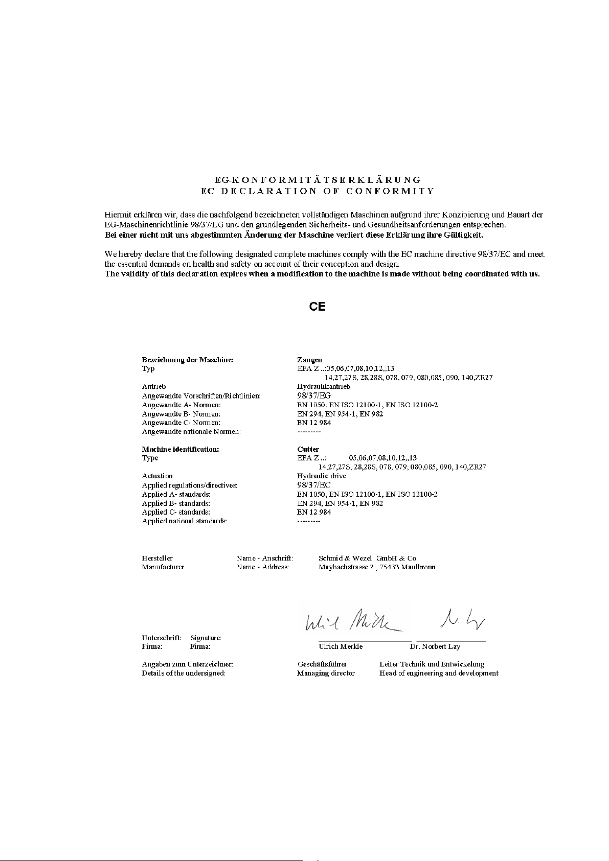
B. Konformitätserklärung / Declaration of Conformity
Schmid & Wezel
D 75433 Maulbronn
Seite/ Page
33/ 33
33
Ausführung/ Version
04.2012
 Loading...