


Betriebsanleitung/ Operating instructions
Wartungsanleitung/ Maintenance instructions
Ersatzteilliste/ Sparepart list
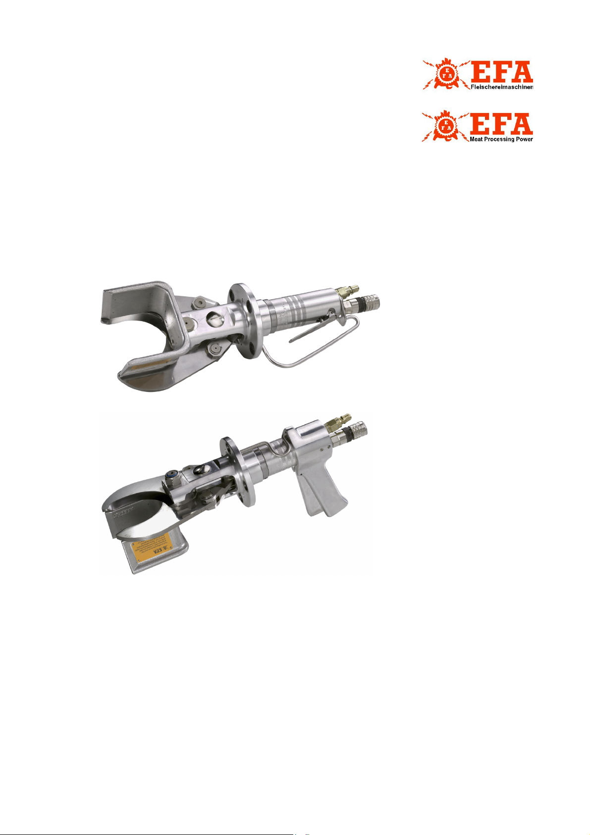
EFA Z079, EFA Z080
Zerlegezange
Hook Cutter
Wichtige Informationen:
Diese Anleitung unbedingt dem Bedienpersonal aushändigen!
Important Informations:
Please forward these operating instructions to your operating
personell!
Schmid & Wezel
D 75433 Maulbronn

INHALTSVERZEICHNIS
1. Verwendung, Lieferumfang, Z
1.1 Symbole in dieser Anleitung ....................................................................................................2
1.2 Bestimmungsgemäße Verwendung ..........................................................................................2
1.3 Lieferumfang ......................................................................................................................... 3
1.4 Zubehör ................................................................................................................................ 3
2. Sicherheitshinweise ........................................................................................................3
2.1 Allgemeine Sicherheitshinweise ............................................................................................... 3
2.2 Verhalten am Arbeitsplatz .......................................................................................................3
3. Inbetriebnahme und Betriebssicherheit..........................................................................3
3.1 Erstinbetriebnahme ................................................................................................................ 4
3.2 Schalterbetätigung ................................................................................................................. 4
3.3 Arbeiten mit der Zerlegezange................................................................................................. 5
4. Montage ..........................................................................................................................6
4.1 Messerwechsel....................................................................................................................... 6
4.2 Ventilwechsel.........................................................................................................................6
4.3 Kolbenwechsel .......................................................................................................................6
4.4 Hydraulikaggregat ..................................................................................................................6
4.5 Einstellung des Federzuges .....................................................................................................7
5. Instandhaltung................................................................................................................7
6. Reinigung und Wartung ..................................................................................................9
6.1 Tägliche Reinigung nach Beendigung der Schlachtungen ...........................................................9
6.2 Tägliche Wartung der Zerlegezange .........................................................................................9
6.3 Erweiterte Wartung
(nach ca. 100 Betriebsstunden)......................................................................................................9
6.4 Reparatur durch den Kundendienst........................................................................................ 10
ubehör ..............................................................................2
7. Transport und Lagerung ................................................................................................10
8. Rücknahme ...................................................................................................................10
A. Anhang..........................................................................................................................11
A.1 Massskizze .......................................................................................................................... 11
A.2 Technische Daten ................................................................................................................ 12
A.3 Liste der Ersatz- und Verschleißteile....................................................................................... 13
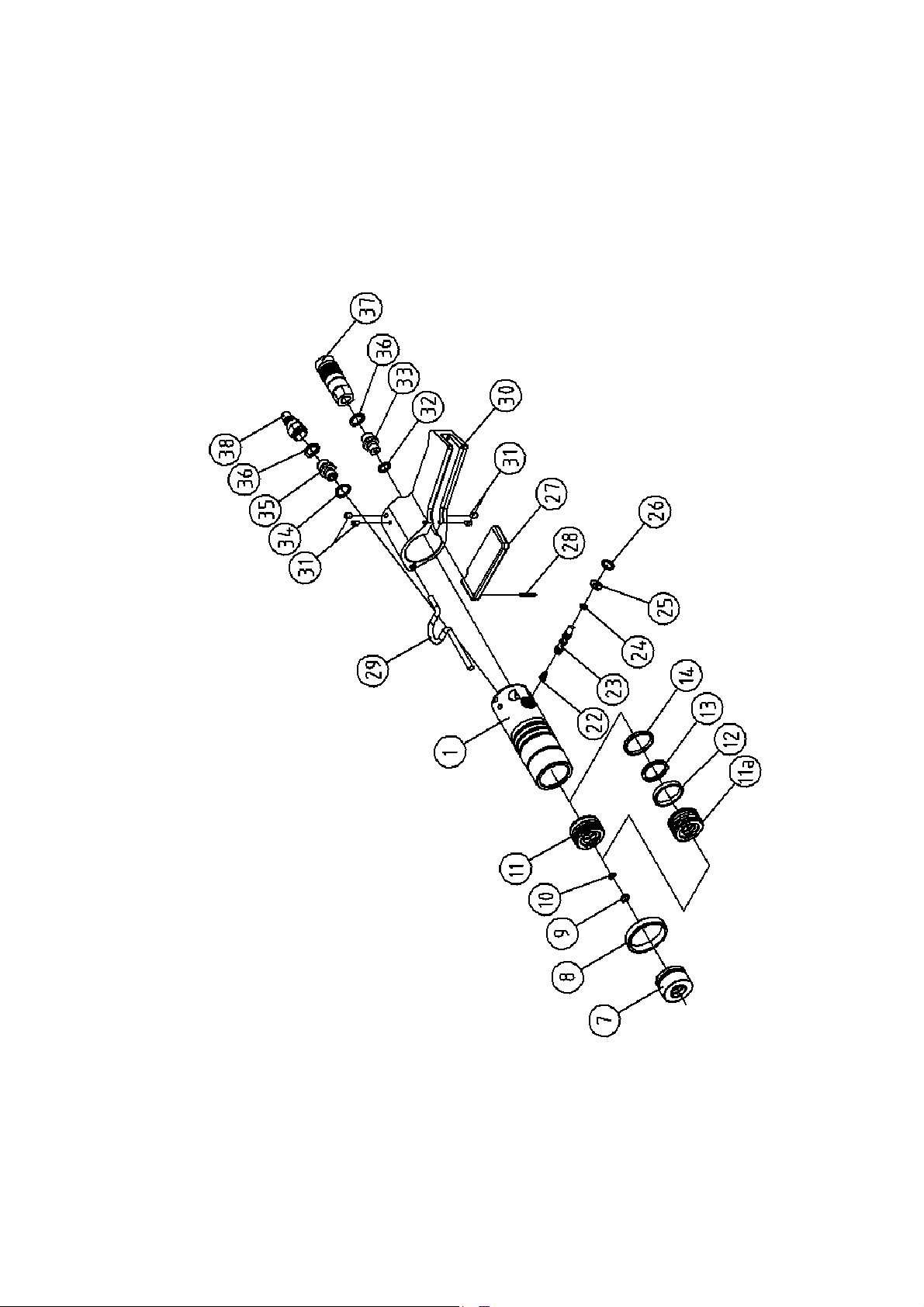
A.4 Explosionszeichnung Z079 .................................................................................................... 15
A.5 Explosionszeichnung Z080 .................................................................................................... 16
A.6 Explosionszeichnung Schlaucheinheit ..................................................................................... 18
B. Konformitätserklärung..................................................................................................19
Schmid & Wezel
D 75433 Maulbronn

1. Verwendung, Lieferumfang,
1.2 Bestimmungsgemäße
Zubehör
Hinweise, unbedingt lesen!
Diese Anleitung richtet sich an den Maschinenbediener. Bewahren Sie sie gut auf!
Die Zerlegezange darf nur betrieben werden:
in technisch einwandfreiem Zustand bestim-
mungsgemäß sowie sicherheits- und gefahrenbewusst
mit allen angebauten Sicherheitseinrichtungen
gemäß den Sicherheitshinweisen
nachdem das Bedienpersonal diese Anleitung,
insbesondere Kapitel 2 "Sicherheitshinweise"
(S. 3) und Kapitel 3 "Inbetriebnahme und
Betriebssicherheit" (S. 3) gelesen und verstanden hat
Nur so können Fehlbedienungen vermieden und
Gefahrensituationen richtig eingeschätzt werden.
Greifen Sie niemals in den
Schneidebereich der Zange, Sie
könnten sich sonst Gliedmaßen
abtrennen!
Tragen Sie beim Arbeiten einen
Augenschutz bzw. eine Schutzbrille!
1.1 Symbole in dieser Anleitung
Gefahrensymbol:
Hier ist äußerste Vorsicht und Umsicht
geboten. Bei Fehlverhalten besteht direkte Verletzungsgefahr für das Bedienpersonal oder Dritte. Außerdem
kann die Maschine Schaden nehmen.
Informationssymbol:
Mit diesem Symbol versehene Textpassagen geben Ihnen wichtige Informationen und nützliche Tipps.
Verwendung
Die Zange dient zum Zerlegen von Fleisch im nicht
gefrorenen oder teilgefrorenen Zustand (ca. 5
°C).
Mit der Zange können vorteilhaft die Klauen, sowie das Geäffter abgeschnitten werden. Die Pfote
kann ebenfalls im Gelenk gelöst werden. Ein
Schnitt außerhalb des Gelenks sollte aus Verschleißgründen vermieden werden.
Die Zange ist geeignet für Abtrenn- und Zerlegearbeiten in Mittel- und Großbetrieben, sowohl für
die Fleisch- als auch für die Geflügelindustrie.
Die Maschine ist für eine andere Nutzung nicht
ausgerüstet. Sollte eine anderweitige Nutzung
vom Bediener gewünscht sein, bitte unbedingt
vorher Rücksprache mit der Firma Schmid & Wezel GmbH & Co. (S&W) halten.
Bei allen anderen Anwendungen muss auf Unfallgefahr bzw. erhöhten Verschleiß hingewiesen
werden. Bei Zuwiderhandlung haftet allein der Benutzer.
1.2.1 Restgefahren
Da die Zange für den industriellen Einsatz an Tierkörpern vorgesehen ist, besteht die Möglichkeit
sich zu verletzen bzw. bei grobem Missbrauch jemanden zu töten. Da auf Grund der bestimmungsgemäßen Verwendung die Öffnungsgröße
zwischen den Zangenmessern nicht verkleinert
werden kann, besteht die Gefahr, den Hals bzw.
den Oberarm oder auch das Schultergelenk zwischen die Zangenmesser zu bringen und die Zange dann auszulösen. Somit ist bei
missbräuchlichem Umgang mit der Möglichkeit
des direkten Todes bzw. des Todes durch Verbluten zu rechnen. Deswegen muss immer auf den
richtigen Umgang mit der Maschine geachtet werden.
Herstellererklärung:
Die Maschine selbst kann keinen Druck aufbauen.
Der Druckaufbau erfolgt erst in Zusammenwirkung mit dem vorgeschalteten Druckerzeugungsgerät und den zugehörigen Schläuchen. Die
Maschine darf erst in Betrieb genommen werden,
wenn alle Anforderungen der Druckgeräterichtlinien hinsichtlich dieses Produktes übereinstimmen.
Schmid & Wezel
D 75433 Maulbronn
Die Maschine ist für einen Druck von 120 bar ausgelegt. Für das Druckvolumen in der Zerlegezange
sowie im Druckerzeuger und den Zuleitungen

kann ein Wert von angenommen
p
werden. Für diese Geräte gilt üblicherweise die
Druckgeräterichtlinie 97/23/EG mit entsprechenden Diagrammen. Auf Grund der soliden Auslegung hinsichtlich Festigkeit und Formsteifigkeit
sowie Stabilität gegenüber statischen wie dynamischen Betriebsbeanspruchungen verweisen wir jedoch auf Artikel 1.3.10 der Druckgeräterichtlinie
97/23/EG:
Weil der Druck keinen wesentlichen Faktor für die
Konstruktion darstellt, unterliegt die EFA Zerlegezange nicht der o.g. Richtlinie.
V 240>⋅
1.3 Lieferumfang
Zerlegezange
Betriebsanleitung
1.4 Zubehör
Federzug
Schlaucheinheit
Aggregat
Hydrauliköl
Die Bestellnummern sowohl für im Lieferumfang
enthaltene Teile wie für Zubehör finden Sie in Anhang A.3 "Liste der Ersatz- und Verschleißteile"
(S. 13).
2. Sicherheitshinweise
2.1 Allgemeine Sicherheitshinweise
Befolgen Sie beim Gebrauch der Zerlegezange unbedingt nachfolgende Sicherheitsmaßnahmen.
Messerwechsel sowie Installations-, Wartungs-
und Reparaturarbeiten dürfen nur bei den vom
Hydrauliknetz abgetrennten Geräten durchgeführt werden
für die Bedienung wird vorausgesetzt, dass das
Bedienpersonal ausreichende Kenntnisse zum
Arbeiten mit Zerlegezangen hat
Einweisung durch unser Fachpersonal
Installations-, Wartungs- und Reparaturarbei-
ten dürfen nur von autorisiertem Fachpersonal
durchgeführt werden
Zerlegezangen von S&W entsprechen den ein-
schlägigen Sicherheitsbestimmungen
2.2 Verhalten am Arbeitsplatz
1. Halten Sie Ihren Arbeitsplatz in Ordnung.
Unordnung kann Unfälle zur Folge haben.
2. Berücksichtigen Sie Umgebungseinflüsse. Sorgen Sie für gute Beleuchtung (min. 500 Lux).
3. Halten Sie andere Personen von Ihrem Arbeitsplatz fern. Arbeiten Sie konzentriert und mit
Vernunft. Benutzen Sie die Zerlegezange nicht,
wenn Sie unkonzentriert und/ oder müde sind.
4. Bewahren Sie die Zerlegezange sicher auf.
Unbenutzte Geräte an einem trockenen Ort
aufbewahren.
5. Arbeitskleidung: Tragen Sie keine weite Kleindung oder Schmuck - diese können von
beweglichen Teilen erfasst werden. Tragen Sie
beim Arbeiten festes Schuhwerk. Tragen Sie
generell ein Haarnetz!
6. Vermeiden Sie eine nicht normale Körperhaltung. Sorgen Sie für sicheren Stand und halten
Sie jederzeit das Gleichgewicht.
7. Pflegen Sie Ihre Werkzeuge mit Sorgfalt. Verwenden Sie nur scharfe und unbeschädigte
Messer, damit Sie besser und sicherer Arbeiten
können.
8. Verwenden Sie nur EFA-Originalmesser. Befolgen Sie die unter Messerwechsel aufgeführten
Vorschriften. Siehe auch Kapitel 4.1.1 "Auswechseln der Messer" (S. 6).
9. Lassen Sie keine Werkzeugschlüssel stecken.
Überprüfen Sie vor dem Einschalten, ob alle
Schlüssel entfernt sind.
10.Verwenden Sie nur EFA-Originalzubehör. Bei
Missachtung erlischt die Gewährleistung. Ein
Gebrauch anderer Einsatzwerkzeuge oder
Zubehöre kann zudem verletzungsgefährdend
für Sie sein.
11.Veränderungen und Umbauten an der
Maschine sind nicht zulässig und entbinden
S&W von jeglicher Gewährleistung und Haftung.
3. Inbetriebnahme und
Betriebssicherheit
Arbeitsplatz
Der Stellplatz für den Bediener sollte mindestens
1,5 qm groß sein. In diesen Bereich sollte kein anderer Arbeitsplatz hineinragen, da sonst auf
Grund der Bewegungen mit der Zange Verletzungsgefahren entstehen könnten.
Schmid & Wezel
D 75433 Maulbronn

Die Beleuchtung des Arbeitsplatzes muss min.
3,9
500 Lux entsprechen.
3.1 Erstinbetriebnahme
Die Zerlegezange nur ausgeschaltet an das Betriebsnetz
anschließen!
Wesentliche Informationen, z. B. technische Datenblätter, Zeichnungen und
Stücklisten finden Sie in Anhang A (S.
11).
3.1.1 Federzug
Die Maschine muss immer in Kombination mit einer Gewichtsentlastung (Federzug) betrieben werden. Bringen Sie diese an einem höher gelegenen
Element über dem Arbeitplatz oder an der Decke
an. Informationen zur Feinabstimmung des Federzuges finden Sie unter .
3.1.3 An- und Abkuppeln der Zange
Die Zange ist mit einem Stecknippel-Vorlauf und
einem Kupplungskörper-Rücklauf ausgerüstet. Gehen Sie wie folgt vor:
Druckluft abstellen und Ventilhebel (27) an
Pfotenzange einmal betätigen. Der Hydraulikschlauch kpl. (33, 36, 37 und 39, Vorlauf/
schließen) ist nun drucklos und die Schlaucheinheit (33, 35-41) kann abgekuppelt werden.
drucklosen Hydraulikschlauch klp. mit
geschlossenem Vorlauf von Schlaucheinheit
abkuppeln
zum Abkuppeln den Sicherheitsschließring am
Kupplungskörper lösen. Dazu den Schließring
umdrehen, bis sich die Arretierung löst
Die Hydraulikkupplungen sind selbstsperrend, so
dass beim Abkuppeln kein Öl ausläuft.
Sie sollten Kupplung und Steckerteile
vor Verschmutzung schützen!
Die Zange möglichst kopflastig aufhängen. Die
Senkrechte kann bei Bedarf nach justiert werden.
Auf Grund des Gewichts von ca. 4,5 kg kann es
beim Befestigen oder Lösen der Gewichtsentlastung zu einer Gefährdung durch Abrutschen oder
Herunterfallen der Maschine kommen. Achten Sie
auch darauf, dass sich die Maschine weder am
Karabinerhaken noch am Haken der Zange verklemmt. Seien Sie umsichtig!
Wenn die Zange nicht benutzt wird, ist diese so
abzulegen, dass es nicht zu unbeabsichtigtem
Kontakt mit den Schneiden kommen kann, denn
diese sind scharf.
3.1.2 Hydraulikaggregat
Der Schneidmechanismus der Zange funktioniert
hydraulisch. Schließen Sie die Zange an ein betriebsbereites Kompakt-Pumpenaggregat an (siehe hierzu auch separate Betriebsanleitung für das
Pumpenaggregat), dazu
geben Sie feingefiltertes Hydrauliköl in die vor-
gesehene Einfüllöffnung
und
schließen das Aggregat über Klemmkasten (Y-
Schaltung 3: 400 V ~, 50 Hz) an.
Die zu verwendenden Hydraulikschläuche haben
unterschiedlich große Gewindeanschlüsse und
können daher nicht falsch angeschlossen werden.
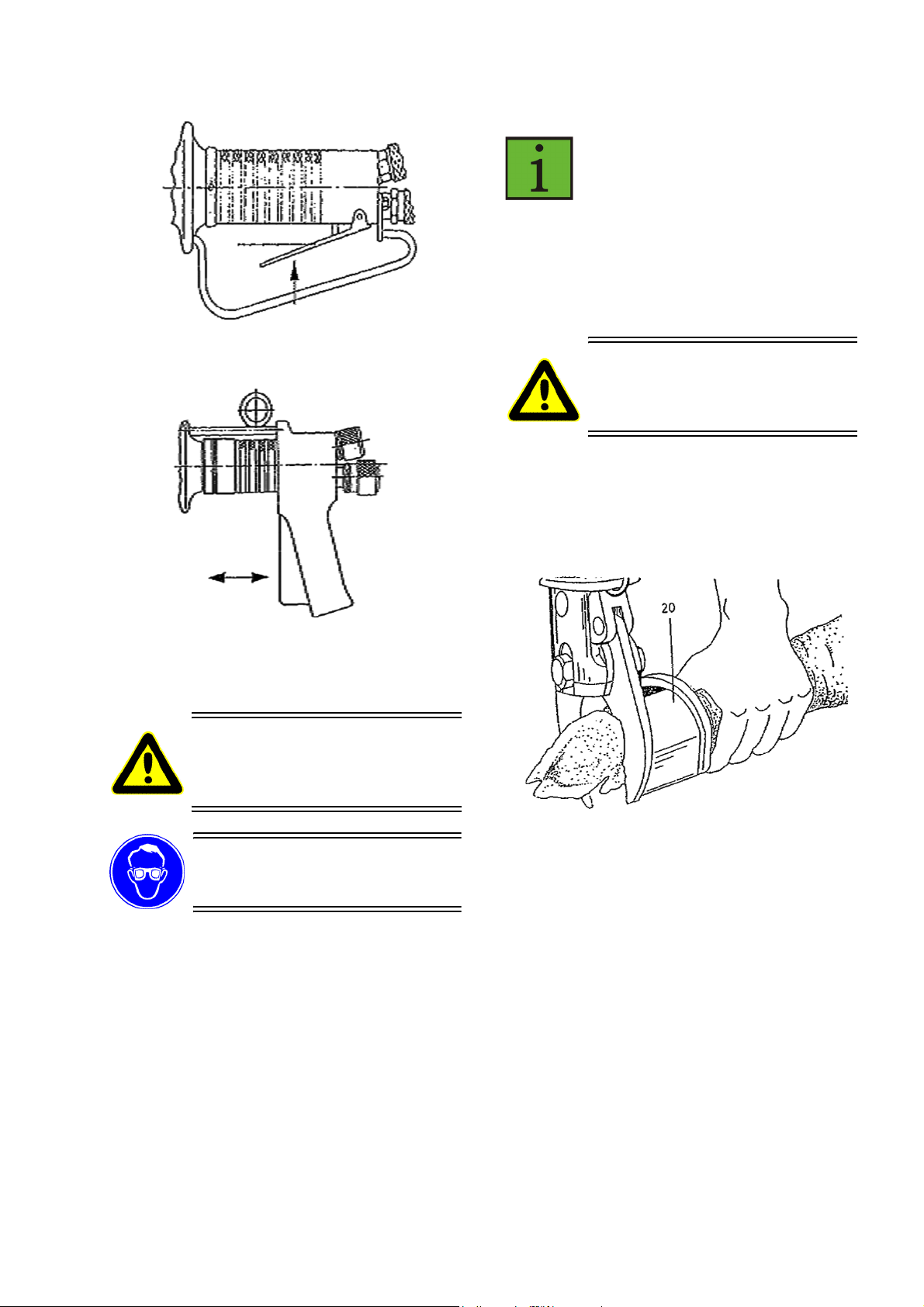
3.2 Schalterbetätigung
Erst nach vorherigem Lesen dieser Bedienungsanleitung und
nach korrektem Anschluss darf
die Zange eingeschaltet werden!
3.2.1 Einschalten
Erst bei korrektem Messerspiel
und richtig montiertem Halter
(20) darf die Zange eingeschaltet
werden!
Zange sicher halten!
V
entilhebel mit Schaltergriff betäti-
gen, um die Messer zu schließen.
3.2.2 Ausschalten
Ventilhebel loslassen, um Messer zu öffnen
Der Schneidvorgang kann jederzeit abgebrochen
oder wiedeholt werden.
Schmid & Wezel
D 75433 Maulbronn
Die Zange immer rechtwinklig und im
-
und nach Kapitel 3.2 Schalterbetätigung
betätigen.
des Schalters ergibt sich der Schnitt.
Maschine am Handgriff sicher halten.
die Schneiden schließen in weniger als 1s.
Schneidebereich (nicht mit den Messer
spitzen) ansetzen. Ansonsten kann es
in Folge einer Überlastung zum Messerbruch kommen.
EIN
AUS
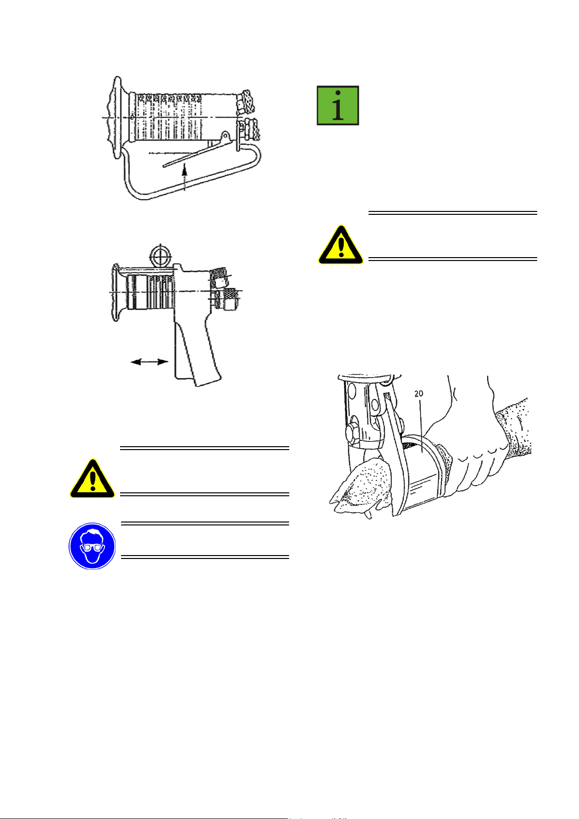
Abbildung 1: Ein-/Ausschalten Z 079
AUS
Abbildung 2: Ein-/Ausschalten Z 080
EIN
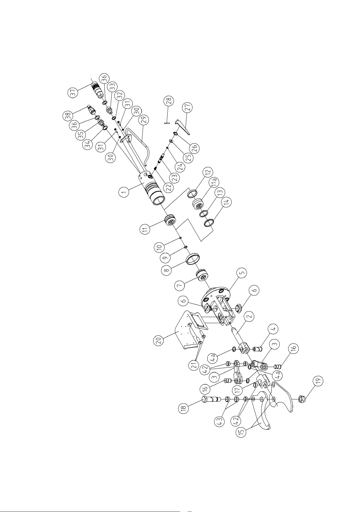
3.3 Arbeiten mit der Zerlegezange
Eine Entlüftung der Zerlegezange ist nicht erforderlich, da nach mehrmaligem Betätigen der Zange die Luft über die Hydraulikschläuche aus dem
Belüftungsfilter des Pumpenaggregates entweicht.
Im eingeschalteten Zustand besonders vorsichtig handeln und
nicht in den Messerbereich greifen.
Aus Sicherheitsgründen muss der beidseitig montierbare Halter (20) der Zange, beim Schneidevorgang auf der Seite der materialhaltenden Hand,
d.h. für Linkshänder rechts und für Rechtshänder
links montiert sein (siehe Abb. 3).
Greifen Sie niemals in den
Schneidbereich der Zange, Sie
könnten sich sonst Gliedmaßen
abtrennen!
Tragen Sie beim Arbeiten einen
Augenschutz bzw. eine Schutzbrille!
3.3.1 Arbeitgang
Pumpenaggregat muss betriebsbereit sein
Zange sicher halten, richtig ansetzen
Der Schneidvorgang kann entweder am hängenden oder am auf dem Tisch liegenden Tier/
Fleisch ausgeführt werden. Der Gerätebediener fixiert den Schnittbereich und durch betätigen
Abbildung 3: Halten der Zange
Die Sicherheitseinrichtungen (Halter(20) und Bügle(29)) dürfen weder verändert noch entfernt
werden.
3.3.2 Betriebssicherheit
beim Zerlegen besonders umsichtig handeln,
stets rechtwinklig und im Schneidebereich
ansetzen, damit in Folge einer Überlastung
kein Messerbruch resultiert.
zur sichereren Handhabung (Führung) die Zer-
legezange an einem Federzug aufgehängen.
Schmid & Wezel
D 75433 Maulbronn

4. Montage
Vor allen Montagearbeiten das
Gerät vom Betriebsnetz trennen!
Die zur Montage notwendigen Zeichnungen finden
Sie in Anhang A.4 "Explosionszeichnung Z079" (S.
15) und Anhang A.5 "Explosionszeichnung Z080"
(S. 16).
4.1 Messerwechsel
4.1.1 Auswechseln der Messer
Messer (15) zufahren.
zen (23) und Druckfeder (22) abnehmen.
Teile reinigen, auf Verschleiß prüfen und in
umgekehrter Reihenfolge montieren.
Die Ventilbüchse ist im Gehäuse eingeschrumpft
und kann nicht gewechselt werden.
4.3 Kolbenwechsel
4.3.1 Auswechseln der Kolbenteile
Für diese Reparatur muss das Montage-Set vorliegen. Dazu mehr im Anhang A.3 "Liste der Ersatzund Verschleißteile" (S. 13).
Messer (15) ausbauen (siehe Kapitel 4.1.1
"Auswechseln der Messer" (S. 6))
Hydraulikaggregat abstellen, durch einmaligen
betätigen des Ventilhebel (27) System drucklos
schalten.
Zange abkuppeln (siehe Kapitel 3.1.3 "An- und
Abkuppeln der Zange" (S. 4)).
Sicherheitsringe (4a) demontieren und beide
Bolzen (16) mit Stift (144) auspressen. Dabei
auf eine saubere Auflage der Gabel achten.
Sechskantmutter (19) und Gewindebolzen (18)
demontieren.
Vor dem Zusammenbau der Zange die demontierten Teile reinigen, auf Verschleiß überprüfen und
gegebenenfalls austauschen. Sämtliche Gleitstellen mit EFA-Spezialfett (136) einfetten.
4.1.2 Überprüfung des Messerspiels
Die Messer müssen (wegen Bruchgefahr) immer
spielfrei und leichtgängig eingestellt sein. Die Einstellung erfolgt über die Sechskantmutter (19).
4.1.3 Messermontage
Vor dem Wiedereinbau die demontierten Teile reinigen, auf Verschleiß überprüfen und gegebenenfalls austauschen. Sämtliche Gleitstellen mit EFASpezialfett (136) einfetten.
Vor Befestigung in den Gabeln (3) die Messer (15)
über die selbstsichernden Sechskantmuttern (19)
leichtgängig und spielfrei einstellen.
Gewindering (8) mit Hakenschlüssel (140)
lösen (Rechtsgewinde).
Gehäuse (1) abschrauben und Kolbenstange
(2) mit Kolben (11) in Richtung Führung vst.
(7) schieben.
beide Gabeln (3) quer stellen und Kolben (11)
mittels Stirnloch-Schlüssel (141) abschrauben.
Der Kolben (11) ist durch Loctite gesichert Demontage nur durch Erwärmen auf 150 °C
möglich.
Ring (14) auf Verschleiß prüfen - Demontage
nur durch Zerstörung möglich.
Führungsrohr im Gehäuse (1) ist eingeschraubt
und mit Loctite gesichert - Demontage nur
durch Erwärmen auf 150 °C möglich.
alle Teile reinigen, auf Verschleiß prüfen und in
umgekehrter Reihenfolge montieren.
Sämtliche Gleitstellen und Messer (15) mit EFASpezielafett (136) einfetten.
Achtung:
Kolben (11) muss mit Loctite 542 gesichert sein!
Ring (14) nur mit Montagekegel (145) und
Spreizhülse (146) montieren.
Abstandsmaß 1 mm von Zangenkörper (5) zu
Gewindering (8) beachten.
4.2 Ventilwechsel
4.2.1 Auswechseln der Ventilteile
Zylinderstift (28) und danach Ventilhebel (27)
demontieren.
Sicherungsring (26), Scheibe (25), Ventilbol-
Schmid & Wezel
D 75433 Maulbronn
4.4 Hydraulikaggregat
Wenigstens einmal im Jahr Ölfüllung ablassen,auf
Verschmutzung kontrollieren und eventuell ersetzen. (Siehe hierzu separate Betriebsanleitung für
das Hydraulikaggregat).

4.5 Einstellung des Federzuges
Die Feinabstimmung des Federzuges erfolgt über
die PLUS/MINUS-Schraube an seinem Gehäuse
(siehe Abb. 4).
Abbildung 4: Federzug
drehen Sie dazu die Schraube in Richtung
MINUS bis sich das Gerät frei schwebend im
Gleichgewicht (mit der Zugfeder) auf Arbeitshöhe befindet.
Tabelle 1: Fehler- und Störungsliste
E =
elektrisches
Aggregat
D =
druckluftgesteuertes
Aggregat
Störung mögliche Ursache Behebung
Sollte kein Auszug möglich sein, ist der Federzug
blockiert und eine Neueinstellung ist notwendig:
drehen Sie die Schraube in Richtung PLUS bis
ein Auszug möglich wird und beginnen Sie
erneut mit der Feineinstellung (siehe oben).
5. Instandhaltung
Während des Betriebes kann die Funktion gestört
sein, die Fehlerbehebung ist in den meisten Fällen
aber relativ einfach. In Tabelle 1: "Fehler- und
Störungsliste" sind diese Störungen mit möglichen
Ursachen und resultierenden Behebungsmöglichkeiten aufgeführt.
1. Druckluftversorgung unterbrochen
Druckluftversorgung überprüfen.
2. Druckluftminderer verstellt Druck an Druckminderer einstel-
len ( 6 bar).
3. Wasserabscheider oder
Öler defekt
Öler oder Wasserabscheider
überprüfen, Wasserabscheider
leeren bzw. reinigen.
4. Saugteil an der Pumpe ver-
D
der Ventilhebel
(27) läuft
Bei Betätigung
schmutzt.
5. Luftfilter an Druckluftpumpe verschmutzt.
Pumpe nicht.
Saugteileinrichtung, Tankeinrichtung, Öl austauschen.
Luftfilter austauschen bzw. reinigen, Luftversorgung auf Verschmutzung bzw. Feuchtigkeit
untersuchen (getrocknete Luft
empfehlenswert).
6. Umsteuerventil an Luftpumpe klemmt durch Verschmutzung oder zu großer
Wasseranreicherung in der
Druckluft
Störungen können durch verschmutzte Luft oder Luftfeuchtigkeit auftreten. Steuerkolben
versuchen gangbar zu machen
oder Umsteuerventil austauschen.
E + D 7. Kolben - Dichtungen defekt Dichtungen austauschen.
E
Hydraulikpumpe zu heiß.
8. Zahnradpumpe oder Druckrohrdefekt
Zahnradpumpe bzw. Druckrohr
austauschen.
Schmid & Wezel
D 75433 Maulbronn

Tabelle 1: Fehler- und Störungsliste
E
E + D
Pumpe läuft,
jedoch kein
Hydraulikdruck
zu der Zange.
Bei Betätigung
des Ventilhebels schließt
Zange nicht.
Pumpe läuft.
Ventilbolzen
(23) lässt sich
nicht über Ventilhebel (27)
eindrücken
9. In dem Hydraulik -Pumpenzylindern sind die Dichtungen oder die
Rückschlagventile defekt.
10.Verschlussnippel (39) des
Hydr.-Rücklaufschlauches
nicht korrekt eingekuppelt.
Verschlusskupplung (33)
an Zange blockiert Ölstrom
11. Defekte Dichtungen ( Teile
9, 10,13 und 14)
12.Messer (15) verklemmt siehe Kapitel 4.1 "Messerwech-
13.Ölstand zu gering Öl nachfüllen (siehe Kapitel 6.3.1
14.Ventilbolzen defekt Ventilbolzen (23) austauschen.
15.Durch Verschmutzung blokkiert
Dichtung austauschen oder bei
defektem Rückschlagventil (nicht
demontierbar) kpl. Pumpenzylinder austauschen.
Nur Druckluftgesteuertes Aggregat:
Druckluft an der Pumpe abstellen.
Elektrisches und druckluftgesteuertes Aggregat:
Abbau des Öldruckes im Rücklauf durch Herausschrauben der
Verschlußkupplung (33). Danach
korrekter Anschluss des Rücklaufschlauches.
Dichtungen austauschen
sel" (S. 6).
"Hydraulikaggregat" (S. 9)
Ventilbolzen (23) demontieren
und reinigen.
Beim Loslassen
des Ventilhebels (27) öffnet
Zange nicht.
Pumpe läuft
Auslaufen von
Öl an der Kolbenstange (2)
16.wie bei 10. - 12. siehe 10. - 12.
17.Ventilbolzen (23) verklemmt, geht nicht in Ausgangsstellung zurück
18.Kolben (11) gelöst oder
gebrochen
19.Defekte Führung vst. (7) Führung (7) demontieren und
20.Defekte Kolbenstange (2) Kolbenstange (22) demontieren
Ventilbolzen (23) demontieren
und prüfen.
Kolben (11) demontieren und
prüfen.
prüfen.
und prüfen.
Schmid & Wezel
D 75433 Maulbronn

6. Reinigung und Wartung
Einen Reinigungsplan und weitere Einzelheiten erhalten Sie unter o.g. Adressen.
Vor allen Reinigungs- und Wartungsarbeiten das Gerät vom Betriebsnetz trennen!
6.1 Tägliche Reinigung nach
Beendigung der Schlachtungen
Ein störungsfreier Dauerbetrieb ist nur dann gewährleistet, wenn die Zerlegezange ständig hygienisch einwandfrei sauber gehalten wird.
Üblicherweise sollte das Gerät vor jeder Reinigung
desinfiziert werden.
Beachten Sie dazu die geltenden Sicherheits- und
Hygieneanforderungen (DIN EN 1672)!
Desinfektionsmittel dürfen weder direkt noch indirekt mit Lebensmitteln in Berührung kommen.
Spülen Sie das Gerät daher nach der Desinfektion
mit klarem Wasser ab.
Keine scharfen Lösungsmittel zusetzen! Keinen Dampf- bzw.
Hochdruckstrahler verwenden!
Gerät nicht in Wasser tauchen!
6.1.1 Desinfektion
Das Gerät während des Betriebes nach jedem
Schnitt mit heißem Wasser (82 °C) desinfizieren.
6.1.2 Reinigung der Zerlegezange
Zur Reinigung das Gerät nach den Arbeitseinsatz
mit Lappen, Bürste und warmen Wasser (40 55°C) reinigen. Hartnäckige oder verkrustete Verschmutzungen müssen eingeweicht werden. Reinigen Sie dazu mit einem Reinigungsmittel, wenn
möglich als Schaum, das Sie auf die zu reinigende
Fläche verteilen und 15 - 20 min. einwirken lassen. Anschließend gelösten Schmutz mit warmen
Wasser manuell abwaschen.
Die o.g. Reinigungsmittel sind nur eine Empfehlung; bei Verwendung von anderen Reinigungsmitteln müssen Materialverträglichkeit sowie
Hygienevorschriften kundenseitig geprüft werden.
6.1.3 Schmiermittel und Hydrauliköl
Das Schmiermittel sowie das Hydrauliköl unterliegen den im Lebensmittelbereich notwendigen Vorschriften (DIN 1672).
Empfohlenes Schmierfett
Klübersynth UH1 14-222 (1 kg Spezialfett in Dose)
Qualität: Zulassung H1
Best.-Nr. 001 365 621
Empfohlenes Hydrauliköl
Shell Risella D15 (ISO VG 10 - ISO VG 68 nach
DIN 51519)
Qualität: Zulassung H1
Best.-Nr. 001 365 614
6.2 Tägliche Wartung der
Zerlegezange
6.2.1 Schmierung
Nach jeder Reinigung die Gelenk- und Gleitstellen
sowie die Messer mit EFA-Spezielfett leicht einfetten.
6.2.2 Messerspiel
Regelmäßig das Messerspiel überprüfen. Wegen
Bruchgefahr müssen die Messer immer leichtgängig und spielfrei eingestellt sein. Ist die Selbstsicherung der Sechskantmutter nicht mehr
gewährleistet, muss diese unverzüglich ausgetauscht werden. Siehe dazu Kapitel 4.1 "Messerwechsel" (S. 6).
6.3 Erweiterte Wartung
Empfohlene Reinigungsmittel
Diversey Lever Tego 2000:
Oberflächenaktives Desinfektionsmittel
Diversey Lever GmbH
Mallaufstr. 50-56, 68219 Mannheim
P3-topax 91:
Oberflächenaktives Desinfektionsmittel
Henkel-Ecolab Deutschland GmbH
Postfach 13 04 06, 40554 Düsseldorf
Schmid & Wezel
D 75433 Maulbronn
(nach ca. 100 Betriebsstunden)
6.3.1 Hydraulikaggregat
Den Ölstand regelmäßig kontrollieren und gegebenenfalls Öl nachfüllen. Siehe auch gesonderte
Betriebsanleitung für Hydraulikaggregat.

Achtung Lebensmittelqualität:
Zulassung H1. Auf Sauberkeit
achten! Einfülltrichter mit feinmaschigem Sieb verwenden
(Maschenweite ca. 0,4 mm).
Das Hydrauliköl ist als gefahrbringender Stoff
klassifiziert und muss entsprechend gebraucht
und entsorgt werden. Hydrauliköl darf keinesfalls
in die Kanalisation oder ins Freie gelangen.
7. Transport und Lagerung
Die Maschine muss in einem trockenen, gelüfteten
Raum gelagert werden.
Die Maschine ist nach Kapitel 6.1.2 "Reinigung der
Zerlegezange" (S. 9) zu reinigen und in trockenem
Zustand zu transportieren.
Es ist darauf zu achten, dass die Maschine beim
Transport nicht beschädigt wird.
6.3.2 Schärfen der Messer
Nicht richtig geschärfte Messer bringen Produktionseinbußen bzw. erhebliche Gefährdung für den
Benutzer.
Wir haben für Sie in unserer Service-Abteilung einen Schärfdienst eingerichtet. Bitte wenden Sie
sich in diesem Fall an die nächstgelegene Vertragswerkstatt oder direkt an unser Stammhaus.
Bei fachgerechtem Einsatz ist ein Nachschärfen
der Messer meist jedoch nicht erforderlich.
Gegebenenfalls können die Messer bei geringer
Materialabnahme auch mit handelsüblichen
Schleifgeräten nachgeschärft werden.
Keine Gewalt anwenden, da Teile
beschädigt werden könnten! Verwenden Sie ausschließlich EFAOriginalersatzteile!
6.4 Reparatur durch den
Kundendienst
8. Rücknahme
Geben Sie Altgeräte zum Entsorgen an das
Stammhaus zurück.
Vor allen Reparaturarbeiten das
Gerät vom Betriebsnetz trennen!
Reparaturen dürfen nur von Fachkräften vorgenommen werden.
Für Reparaturen steht Ihnen unsere Serviceab-
teilung zur Verfügung. Bitte wenden Sie sich im
Falle einer Reparatur an die nächstgelegene
Vertragswerkstatt oder direkt an unser Stammhaus.
Auf Wunsch können für die Reparaturwerkstatt
mit Fachkräften Ersatzteillisten nachgereicht
werden.
Schmid & Wezel
D 75433 Maulbronn

A. Anhang
A.1 Massskizze
Schmid & Wezel
D 75433 Maulbronn

A.2 Technische Daten
3,9
3,9
EFA Z079 EFA Z080
Betriebsdruck 120 bar 120 bar
Luftverbrauch/ Last (Steuerluft) ca. 30 l/ Schnitt ca. 30 l/ Schnitt
Schließzeit/ Öffnungszeit der Zangen 1,2 s 1,2 s
Zangenöffnung 80 mm 80 mm
Schalldruckpegel (EN ISO 11688-1) < 85 dB(A) < 85 dB(A)
Hand-Arm Vibration (EN 28662)
Gewicht 4,5 kg 4,5 kg
Tragkraft des Federzug 30 - 50 N 30 - 50 N
Aggregatanschluss 400 V ~/ 50 Hz 400 V ~/ 50 Hz
Schlauchlänge 5 m 5 m
< 2,5 m/ s
2
< 2,5 m/ s
2
Schmid & Wezel
D 75433 Maulbronn

A.3 Liste der Ersatz- und Verschleißteile
007 011 419
007 011 419
007 011 418
007 011 418
003 011 419
003 011 419
007 010 260
007 010 578 003 014 367
003 006 455
Z079 Z080
Bild-
Nr.
1 1 Gehäuse vst. 007 009 558 007 009 710
2 1 Kolbenstange vst 007 009 566 007 009 566
3 2 Gabel vst. 007 009 567 007 009 567
4 1 Bolzen 003 009 571 003 009 571
4a 3 Sicherungsring 001 317 912 001 317 912
5 1 Zangenkörper
6 2 Verschlussstopfen 001 368 644 001 368 644
6a 2 Verschlussgewinde 001 368 643 001 368 643
7 1 Führung vst. 007 009 564 007 009 564
8 1 Gewindering 003 009 563 003 009 563
9 1 Ring 001 607 121 001 607 121
10 1 O-Ring 001 312 695 001 312 695
11 1 Kolben vst. (mit 11a-14) 007 006 721 007 060 721
11a 1 Kolben 003 006 391 003 006 391
12 1 Kolbenführungsring 001 607 122 001 607 122
13 1 O-Ring 001 312 694 001 312 694
14 1 Ring 001 607 120 001 607 120
15 2 Messer vst. 007 009 568 007 009 568
16 2 Bolzen 003 009 570 003 009 570
17 1 Paar Spannteil 003 009 572 003 009 572
18 1 Gewindebolzen 003 009 569 003 009 569
19 1 Sechskantmutter 001 304 505 001 304 505
20 1 Halter
21 2 Senkschraube mit I.-Skt. 001 326 508 001 326 508
22 1 Kegelfeder 003 001 445 003 001 445
23 1 Ventilbolzen vst. 007 009 561 007 009 561
24 1 O-Ring 001 312 697 001 312 697
25 1 Scheibe 003 007 485 003 007 485
26 1 Sicherungsring 001 312 308 001 312 308
27 1 Ventilhebel 003 001 575 --27a 1 Ventilhebel vst. --- 007 014 364
28 1 Zylinderstift 001 306 418 001 306 418
29 1 Bügel vst. 007 006 386 --29a 1 Aufhängung --- 003 009 001
30 2 Federring 001 317 007 --30 a 1 Griff --- 003 008 998
31 2 Sechskantschraube 001 325 911 --31a 4 Gewindestift --- 001 326 306
32 1 Dichtring 001 314 306 001 314 306
33 2 Gewindenippel 001 367 105 001 367 105
34 1 Dichtring 001 314 308 001 314 308
35 2 Gewindenippel 001 367 106 001 367 106
36 4 Dichtring 001 314 307 001 314 307
37 2 Kupplungskörper 001 607 158 001 607 158
Stück Benennung Best.-Nr.
Zerlegezange 008 009 556 008 009 711
Schmid & Wezel
D 75433 Maulbronn

38 2 Stecknippel 001 607 159 001 607 159
42 4 Gleitlagerbuchsen 002 000 307 002 000 307
43 2 Gleitlagerbuchsen 002 000 309 002 000 309
Schlaucheinheit kpl.
(33, 35 - 41)
Vorlauf
Rücklauf
39 1 Hochdruckschlauch 001 607 118 001 607 118
40 1 Hochdruckschlauch 001 606 582 001 606 582
41 10 Kabelbinder 001 371 913 001 371 913
133 1 Hydrauliköl 001 365 614 001 365 614
134 1 Federzug 001 620 036 001 620 036
135 1 Spezialöl 5 l
136 1 Spezialfett 001 365 621 001 365 621
1 Montage-Set
140 1 Hackenschlüssel 001 370 205 001 370 205
141 1 Stirnlochschlüssel 001 369 705 001 369 705
144 1 Drehstift 001 366 005 001 366 005
145 1 Montagekegel 003 006 661 003 006 661
146 1 Spreizhülse 003 006 662 003 006 662
Hydraulikschlauch kpl.
je 1 Stück (33, 36, 37,
39a)
Hydraulikschlauch kpl.
je 1 Stück (35, 36, 38,
40)
Sonderzubehör
(für Wartungseinheit)
(140 - 146)
008 009 579 008 009 579
001 607 160 001 607 160
001 607 179 001 607 179
001 365 612 001 365 612
007 899 668 007 899 668
Verschleiß-Set für Pfo-
tenzange (4, 4a, 7, 9, 10,
12, 13, 14, 16, 18, 19,
22, 24, 25, 26)
007 899 483 007 899 483
Schmid & Wezel
D 75433 Maulbronn
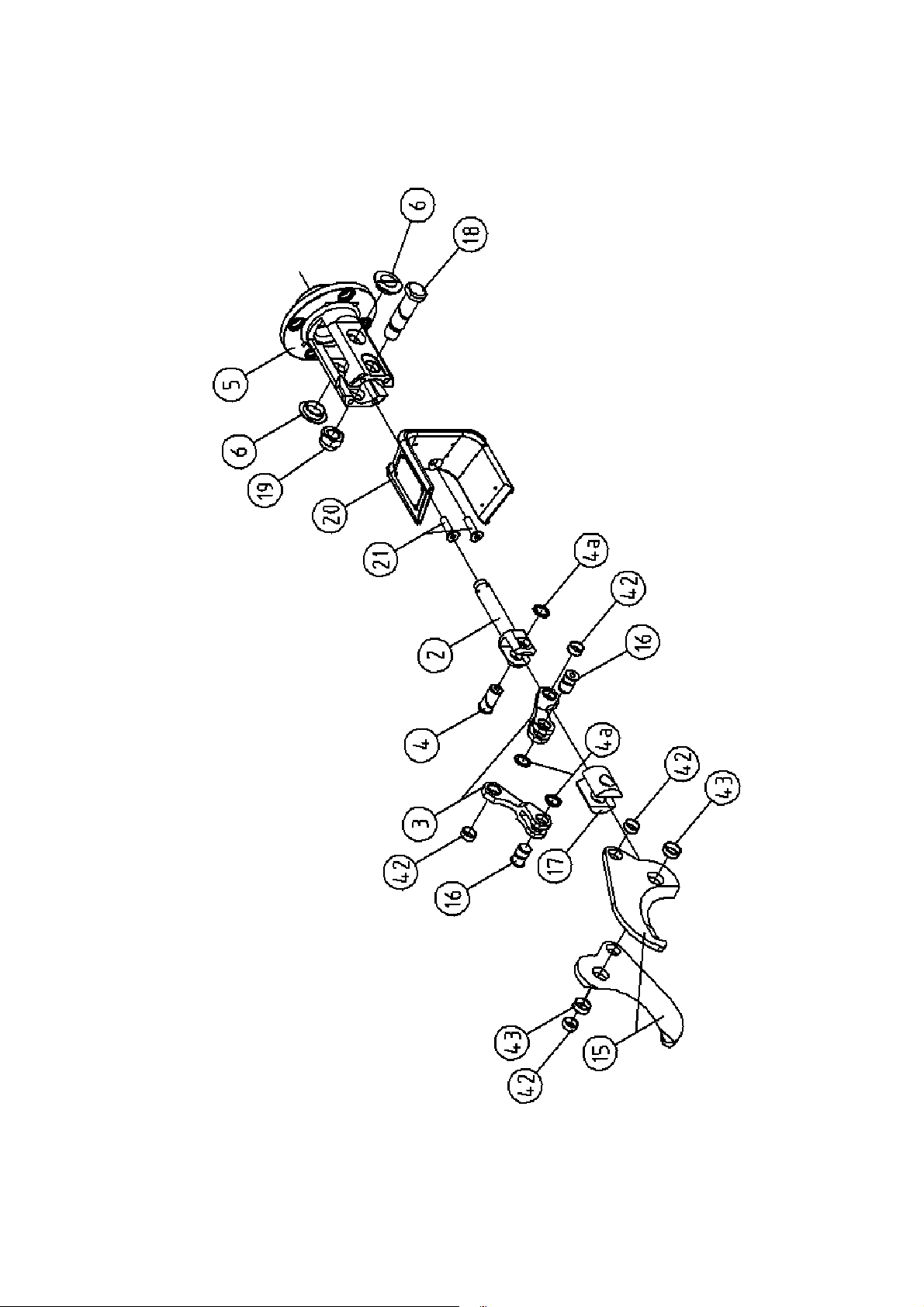
A.4 Explosionszeichnung Z079
Schmid & Wezel
D 75433 Maulbronn
A.5 Explosionszeichnung Z080
Schmid & Wezel
D 75433 Maulbronn

Schmid & Wezel
D 75433 Maulbronn

A.6 Explosionszeichnung Schlaucheinheit
Schmid & Wezel
D 75433 Maulbronn
Operating instructions/ Betriebsanleitung
Maintenance instructions/ Wartungsanleitung
Sparepart list/ Ersatzteiliste
EFA Z079, EFA Z080
Hook cutter
Zerlegezange
Important information:
Please forward these operating instructions to your operating
personell!
Wichtige Informationen:
Diese Anleitung unbedingt dem Bedienpersonal aushändigen!
Schmid & Wezel
D75433 Maulbronn,

TABLE OF CONTENTS
1.
Application, scope of delivery and accessories ................................................................2
1.1 Symbols used in this manual ...................................................................................................2
1.2 Proper use............................................................................................................................. 2
1.3 Scope of delivery....................................................................................................................3
1.4 Accessories............................................................................................................................3
2. Safety instructions ..........................................................................................................3
2.1 General safety instructions...................................................................................................... 3
2.2 Workplace safety....................................................................................................................3
3. Commissioning and operational safety............................................................................3
3.1 Commissioning.......................................................................................................................4
3.2 Operation of switches ............................................................................................................. 4
3.3 Working with the hook cutter ..................................................................................................5
4. Assembly ......................................................................................................................... 6
4.1 Replacement of blade ............................................................................................................. 6
4.2 Replacement of valve .............................................................................................................6
4.3 Replacement of piston ............................................................................................................6
4.4 Hydraulic unit ........................................................................................................................6
4.5 Adjustment of spring-loaded pulley.......................................................................................... 7
5. Maintenance....................................................................................................................7
6. Cleaning and maintenance ..............................................................................................9
6.1 Daily cleaning at shift end.......................................................................................................9
6.2 Daily servicing of hook cutter ..................................................................................................9
6.3 Overhaul Service
(after abt. 100 operating hours).....................................................................................................9
6.4 Repairs by S&W customer service technicians......................................................................... 10
7. Transport and storage ...................................................................................................10
8. Disposal.........................................................................................................................10
A. Appendix .......................................................................................................................11
A.1 Dimension Drawing .............................................................................................................. 11
A.2 Technical data ..................................................................................................................... 12
A.3 List of Spare Parts and Wear Parts.........................................................................................13
A.4 Exploded View of Z079 ......................................................................................................... 15
A.5 Exploded View of Z080 ......................................................................................................... 16
A.6 Explosion View of hose kit .................................................................................................... 18
B. Declaration of conformity .............................................................................................19
Schmid & Wezel
D 75433 Maulbronn

1. Application, scope of
p
1.2 Proper use
delivery and accessories
Important notes!
This manual has been specifically compiled for
machine operators. Keep it near the machine for
future reference!
The hook cutter may only be operated
for the intended purpose, with due care as
regards safety, and if the equipment is in
proper working order
if all safety devices are properly mounted
according to the safety instructions
after instruction of the operating personnel,
who must also have read and understood the
instructions in chapter 2 "Safety instructions"
(page 3) and chapter 3 "Commissioning and
operational safety" (page 3).
This is necessary in order to prevent incorrect
operation and to enable operators to assess
potential risks accurately.
Never reach into the operating
range of the cutting blades, as
there is a risk of
dismemberment!
Always wear goggles or other
effective eye protection!
1.1 Symbols used in this manual
Danger:
Proceed with extreme caution. In the
event of incorrect operation, there is a
risk of injury to operating staff and
other persons. There is also a risk of
damage to the machine.
The hook cutter is designed for the cutting of
non-frozen or partially frozen meat (temperature
approx. 5 °C).
The hook cutter is particularly useful for the
cutting of feet and behinds. It can also be used
for the cutting off of paws at the joint. Cut only at
joints to protect the device against damage from
excessive wear.
It is suitable for cutting and breaking in large and
medium-sized meat and poultry processing plants.
The machine is not designed for any other use. If
you wish to use the equipment for other
purposes, first consult Schmid & Wezel GmbH &
Co (S&W).
If the machine is used for any other purposes,
please note that there is a greater risk of serious
injury and increased wear to machine parts. The
operator shall be solely liable for any damage
arising from improper use of the equipment.
1.2.1 Residual risks
As the hook cutter is designed for the cutting of
animals, there is a risk of serious injury to
persons. For proper use, the clearance between
the cutter blades may not be reduced. It is
therefore possible to place the blades around the
neck, upper arm or shoulder joint of a person and
to release the cutter. If handled improperly or
without due care, persons might even be killed
instantly, or die as a consequence of serious
blood loss. It is therefore imperative that the
cutter is handled properly and according to the
instructions in this manual.
Manufacturer’s declaration
The machine cannot generate pressure. Pressure
build-up occurs only in conjunction with the
connected pressure generator and hose
connections. The machine may only be
commissioned if all requirements of the directives
and regulations governing pressurised vessels are
fulfilled.
Information:
This symbol highlights sections in the
text containing important information
and useful hints.
Schmid & Wezel
D75433 Maulbronn,
The machine is designed for a pressure of 120
bar. The pressure volume in the hook cutter, as
well as in the pressure generator and the supply
lines is (estimate value). Such
devices must generally meet the requirements of
the Pressure Vessel Directive 97/23/EC and
related diagrams: Due to the sturdy design
ensuring great dimensional stability and strength,
V 240>⋅

as well as resistance against static and dynamic
stress during operation, article 1.3.10 of the
Pressure Vessel Directive 97/23/EC applies.
As pressure is not a decisive factor when it comes
to the design of the cutter, the EFA hook cutter is
not subject to the above directive.
1.3 Scope of delivery
suitable for the use of the tool and properly
illuminated (min. 500 lux).
3. Prevent unauthorised persons from accessing
your workplace. Concentrate on your work and
use common sense. Do not handle the hook
cutter, if you feel tired and/or find it difficult to
concentrate.
4. Keep the hook cutter in a safe place. While not
in use, store it in a dry place.
Hook cutter
Operating manual
1.4 Accessories
Spring-loaded pulley
Hose kit
Hydraulic unit
Hydraulic fluid
For order numbers of standard equipment and
accessories, please refer to Appendix A "List of
Spare Parts and Wear Parts" (page 13).
2. Safety instructions
2.1 General safety instructions
When operating the hook cutter, always adhere to
the following safety instructions:
Before replacing the cutter blades, or carrying
out installation, maintenance or repair work,
disconnect the machine from the hydraulic
network.
Only personnel who have been properly trained
and instructed in the safe use of the hook
cutter may handle the tool.
All personnel working with the tool must be
instructed by our specialist technicians.
Installation, maintenance and repair work may
only be carried out by suitably trained and
authorised specialists technicians.
Hook cutters by S&W conform to all relevant
safety standards.
5. Work clothing: Do not wear loose clothing or
jewellery, as such items could become
entangled in moving machine parts. Wear
safety footwear. Always wear a hairnet!
6. Avoid an unnatural posture. Make sure that
you stand firmly and do not lose your balance.
7. Handle your tools with care. Use only sharp
and undamaged cutter blades to ensure safe
and efficient working.
8. Use only original EFA blades. Always adhere to
the instructions for the replacement of blades.
See also chapter 4.1.1 "Removing blade" (page
6).
9. Never leave spanners or wrenches attached to
the tool. Before starting the machine, inspect
the cutter to ensure that all spanners and
wrenches have been removed.
10.Use only original EFA accessories. Warranty is
voided, if other accessories are used. If other
tools inserts or accessories are used, there is
also an increased risk of injury to the operator
and other persons.
11.It is prohibited to modify the machine in any
way. S&W rejects any liability for damages
arising from modified equipment.
3. Commissioning and
operational safety
Workplace
The working area for the operator must be at
least 1.5 m². This area must be kept clear and
may not be shared with any other staff, as the
cutter is moved during operation and could injure
other persons.
The working area must be illuminated with min.
500 lux.
2.2 Workplace safety
1. Keep your workplace tidy. Any kind of clutter
lead to an increased risk of injury!
2. Ensure that the workplace environment is
Schmid & Wezel
D75433 Maulbronn,
3.1 Commissioning
valve arm
When connecting the hook cutter
to the pressure supply line,
ensure that it is switched off
For detailed information, technical
data, parts lists and drawings of the
equipment, see Appendix A (page 11).
Disconnect pressure air and operate valve lever
(27) once. The hydraulic hoses (33, 36, 37 and
39, infeed/closed) are now depressurised. The
hose unit (33, 35-41) can now be
disconnected.
Disconnect hydraulic hose with closed feed line
from the hose kit
To disconnect the lines, open the safety locking
ring at the coupling body. by turning the
locking ring until it disengages.
3.1.1 Spring-loaded pulley
The machine may only be operated in conjunction
with a spring-loaded pulley. The pulley must be
attached to a beam above the workplace or the
ceiling. For detailed information on how to install
and balance the spring-loaded pulley, please refer
to chapter 4.5 "Adjustment of spring-loaded
pulley" (page 7)
The hook cutter must be suspended in such a way
that it head section faces downwards. If required,
the tool can be realigned in vertical direction.
As the machine weighs about 4.5 kg, there is a
risk of injury if it is dropped while being attached
or removed from the pulley system. Ensure that
the hook cutter is not jammed at the hooks.
Always proceed with special care when attaching
or removing the saw from the pulley.
When the cutter is not used, it must be stored in
such a way that persons cannot inadvertently
come into contact with its blades, as they are
extremely well honed.
3.1.2 Hydraulic unit
The hydraulic couplings are self-locking, so that
no fluid can escape when the line is disconnected.
Protect coupling and adapter
components against contamination!
3.2 Operation of switch
Prior to switching on the cutter,
read the instructions in this
manual carefully and ensure that
the tool is properly connected.
3.2.1 Switching ON
Before switching on the cutter,
check blades for correct play and
ensure that the handle is properly
mounted.
The hook cutter blades are operated hydraulically.
Connect the cutter to a hydraulic unit (for
installation and commissioning, see separate
operating manual) and
fill filtered hydraulic fluid through the refill
opening (volume: approx. 8 l).
connect the hydraulic unit to terminal box for
power supply (Y-circuit 3: 400 V ~, 50 Hz).
The hydraulic hoses supplied with the unit have
threaded connectors of different diameter so that
lines cannot be confused.
3.1.3 Connecting and disconnecting of
cutter
The cutter is equipped with a plug-in nipple feed a
coupling body at the return line. To connect the
cutter, proceed as follows:
Schmid & Wezel
D75433 Maulbronn,
Hold cutter firmly!
Simultaneously press the
to close the cutter.
3.2.2 Switching OFF
Release the valve arm; the cutter opens.
The cutting procedure can be terminated at any
time, or repeated.
Place the cutter at right angles to the
under 1
meat you wish to cut. Ensure that the
meat is placed between the blades and
not just at the tips, as the blades might
otherwise break.
ON
OFF
Figure 1: Switching On/Off Z 079
OFF
Figure 2: Switching On/Off Z 080
ON
3.3 Working with the hook cutter
There is no need to bleed the hook cutter, as the
air is automatically released from the bleeding
filter of the pump unit after a number of cuts have
been completed.
While the cutter is on, proceed
with special care caution and do
not reach between the blades.
For safety reasons, the holder of the cutter (20),
that can be mounted on either side must be
mounted on the side of the hand that holds the
material. For left-handed persons, it must thus be
on the right side, and for right-handed persons,
on the left (fig. 3).
Never reach into the operating
range of the cutting blades, as
there is a risk of dismemberment!
Always wear goggles or other
effective eye protection!
3.3.1 Cutting procedure
Ensure that the pump unit is in proper working
order and ready for operation.
Hold cutter firmly, place at the section you
wish to cut and operate the
switch (see chapter 3.2 "Operation of
switch " (page 4)).
For cutting, the meat can be suspended or placed
on a workbench. By positioning the cutter
properly where the meat is to be cut and by
operating switch a clean cut can
be achieved.
Figure 3: Holding of cutter
The safety devices (holder (20) and bracket (29))
may not be modified or removed.
3.3.2 Operational safety
Hold hook cutter at the
handle
Proceed with cutting; be very careful, as the
blades close seconds after switching
on.
Cut meat at right angles; place blades (and not
just tips of the blades) onto the meat in order
to prevent overload and damage to blades.
For safe operation, the hook cutter should be
attached to a spring-loaded pulley system.
Schmid & Wezel
D75433 Maulbronn,

4. Assembly
Before carrying out any assembly
work, disconnect the cutter from
the power supply!
Clean the parts, inspect for wear and assemble
unit by following the above instructions in
reverse order.
The valve casing is shrink-fitted into the housing
and cannot be replaced.
For correct assembly, please refer to the drawings
in Appendix A.4 "Explosion View of Z079" (page
15) and Appendix A.5 "Explosion View of Z080"
(page 15).
4.1 Replacement of blade
4.1.1 Removing blade
Close cutter so that the blades (15) touch.
Switch off the hydraulic unit and press the
valve lever (27) once to release all pressure
from the system.
Disconnect cutter (see chapter 3.1.3
"Connecting and disconnecting of cutter" (page
4)).
Remove lock washers (4a) and push out both
bolts (16) with pin (144). Ensure that the fork
is properly aligned.
Remove hexagon nut (19) and stud bolt (18).
Prior to reassembling the cutter, clean all parts,
inspect for wear and replace, if necessary. Apply
EFA special grease (136) to all sliding surfaces.
4.1.2 Inspection of blade play
In order to prevent breakage, the blades must be
adjusted so that they move easily without
excessive play. Adjust the clearance with the
hexagon nut (19).
4.1.3 Mounting of blades
Prior to reassembling the cutter, clean all parts,
inspect for wear and replace, if necessary. Apply
EFA special grease (136) to all sliding surfaces.
Prior to securing the forks (3). adjust the
clearance of the blades (15) with the self-locking
hexagon nuts (19).
4.3 Replacement of piston
4.3.1 Replacement of piston parts
For repairs, you need a specially devised assembly
kit. For details, please refer to Appendix A "List of
Spare Parts and Wear Parts" (page 13).
Dismantle the blades (15) (see chapter 4.1.1
"Removing blade" (page 6)).
Loosen the threaded ring (8), using the hook
spanner (140) (right-hand thread).
Remove the housing (1) and push the piston
rod (2) together with the piston (11) in the
direction of the guide.
Position both forks (3) diagonally and remove
piston (11) using the face spanner (141). The
piston (11) is secured with Loctite. To remove
it, heat it to 150 °C
Inspect ring (14) for wear. It can only be
removed by breaking it.
The guide tube is screwed into the housing (1)
and secured with Loctite. To dismantle it must
be heated to 150 C.
Clean all parts, inspect for wear and assemble
unit by following the above instructions in
reverse order.
Apply EFA special grease (136) to all sliding
surfaces and the blades (15).
CAUTION:
The piston (11) must be secured with Loctite 542!
To mount the ring (14), always use the
assembly cone (145) and the expansion sleeve
(146).
Keep a clearance of 1 mm between the cutter
body (5) and the treaded ring (8).
4.2 Replacement of valve
4.2.1 Replacement of valve parts
Dismantle the straight pin (28) and the valve
lever (27).
Remove the circlip (26), shim (25), valve bolt
(23) and pressure spring (22).
Schmid & Wezel
D75433 Maulbronn,
4.4 Hydraulic unit
At least once every year, drain off the fluid,
inspect it for contamination and replace it, if
necessary. (For detailed instructions, see also the
separate operating manual of the hydraulic unit).

4.5 Adjustment of spring-loaded
pulley
The spring-loaded pulley can be adjusted by
turning the PLUS/MINUS screw at the housing
(see fig. 4).
Figure 4:Spring-loaded pulley
Turn the screw in MINUS direction until the
tool is balanced and suspended at the correct
Table 1: Troubleshooting
E =
Electric unit
P =
Pneumatic
unit
Malfunction/
fault
Possible cause Remedy
height.
If it is not possible to pull more cable from the
pulley, it is jammed and must be readjusted.
Turn the screw in PLUS direction until cable
can be pulled from the pulley and repeat the
fine adjustment (see above).
5. Maintenance
Malfunctions that might occur during operation
can generally be eliminated by simple means. The
most common malfunctions, their causes and
remedies are compiled in Table 1:
"Troubleshooting".
1. Compressed air supply
blocked or defective
2. Pressure reducer
incorrectly set
3. Water trap or oiler
defective
The valve levers
P
E + P 7. Piston seals are defective Replace seals.
E
(27) are
operated, but
the pump is not
working.
Hydraulic pump
is overheating.
4. Suction unit of pump dirty Replace suction unit, tank or oil.
5. Air filter at compressor
dirty
6. Reversing valve at the air
pump is blocked, due to air
contamination or excessive
air humidity
8. Gear pump or pressure
tube is defective
Check compressed air system.
Adjust pressure (6 bar) at the
pressure reducer.
Inspect oiler/water trap, empty
and clean water trap, if
necessary.
Clean or replace air filter, inspect
compressed air lines for
contamination or moisture (we
recommend using dried air).
Contaminated or damp air can
lead to serious malfunction. Try
repairing the control piston or
replace the reversing valve.
Replace gear pump or pressure
tube
Pump is
running, but
E
Schmid & Wezel
D75433 Maulbronn,
there is no
pressure at the
cutter.
9. Seals or check valves at the
hydraulic pump cylinders
are defective.
Replace seals; if a check valve is
defective, replace pump cylinder
(check valves cannot be
dismantled).

Table 1: Troubleshooting
E + P
The cutter is not
closing when
the valve lever
is operated.
Pump is running
Valve bolt (23)
is not operated
when the valve
lever (27) is
pressed.
The cutter is no
opening when
the valve lever
(27) is released.
Pump is running
10.The nipple (39) at the
hydraulic return hose is not
properly connected. Oil
flow is blocked at the
coupling (33) of the cutter.
11. Seals (parts 9, 10.13, and
14) are defective
12.Blade (15) is jammed see chapter 4.1 "Replacement of
13.Hydraulic fluid level too low Refill fluid (see chapter 6.3.1
14.Valve bolt is defective Replace valve bolt (23).
15.Valve blocked by dirt
16.see 10 -12 see 10 – 12.
17.Valve bolt (23) is jammed
and does not return to its
initial position
18.Piston (11) is loose or
defective
Only pneumatic unit:
Switch off pump.
Electric and pneumatic unit:
Release oil pressure in the return
line by removing the coupling
(33). Reconnect return hose
properly.
Replace seals.
blade" (page 6)
"Hydraulic unit" (page 9))
Remove valve bolt (23) and
clean it.
Remove and check valve bolt
(23).
Remove and check piston (11).
Oil escapes at
the piston rod
(2)
19.Piston guide is defective
(7)
20.Piston rod is defective (2) Remove and check piston rod
Remove and check piston guide
(7).
(22).
Schmid & Wezel
D75433 Maulbronn,

6. Cleaning and maintenance
compliance with the applicable hygiene
regulations.
Before carrying out any cleaning
or maintenance work, disconnect
the cutter from the power supply!
6.1 Daily cleaning at shift end
For disruption-free operation, ensure that the
hook cutter is always kept clean. Disinfect tool
before cleaning it.
Always comply with the relevant safety and
hygiene requirements (DIN EN 1672)!
Ensure that disinfectants are not brought into
contact with food, whether directly or indirectly.
Rinse tool thoroughly with water to remove all
disinfectant.
Do not use aggressive
detergents! Do not clean with
steam or high-pressure water
jet! Do not immerse cutter in
water!
6.1.1 Disinfection
During operation, disinfect the cutter after each
cut with hot water (82 °C).
6.1.2 Cleaning
After each shift, clean the cutter with a brush and
cloth, using warm water (40 - 55 °C) . To remove
persistent or encrusted dirt, soak it in warm
water. Apply detergent, possibly in the form of
foam, on the affected area and let soak for 15 to
20 minutes. Wash with warm water.
Recommended cleaning agents
Diversey Lever Tego 2000:
surface-active disinfectant
Diversey Lever GmbH
Mallaufstr. 50-56, 68219 Mannheim, Germany
P3-topax 91:
surface-active disinfectant
6.1.3 Lubricants and hydraulic fluid
The lubricant and the hydraulic fluid must meet
the requirements of the relevant regulations (DIN
1672) as regards suitability for use in food
processing.
Recommended lubricant
Klübersynth UH1 14-222 (1 kg special grease, in
tin)
Quality: H1 approved
Order no. 001 365 621
Recommended hydraulic fluid
Shell Risella D15 (ISO VG 10 - ISO VG 68
according to DIN 51519)
Quality: H1 approved
Order no. 001 365 614
6.2 Daily servicing of hook cutter
6.2.1 Lubrication
After cleaning, apply little EFA special grease onto
the sliding surfaces, hinges and blades.
6.2.2 Blade play
Regularly inspect blade play. In order to prevent
breakage, the blades must be adjusted so that
they move easily without excessive play. If the
self-locking mechanism of the hexagon nut is not
working properly, immediately replace the nut.
See also chapter 4.1 "Replacement of blade"
(page 6).
6.3 Overhaul Service
(after abt. 100 operating hours)
6.3.1 Hydraulic unit
Regularly inspect oil fluid filling level and refill
fluid, if necessary. For detailed instructions, see
separate operating manual of the hydraulic unit.
Henkel-Ecolab Deutschland GmbH
Postfach 13 04 06, 40554 Düsseldorf, Germany
For a cleaning schedule and detailed instructions,
contact the above suppliers.
The detergents listed above are recommended
products. If you wish to use another product, you
are obliged to test it as regards suitability and
Schmid & Wezel
D75433 Maulbronn,
Food-grade hydraulic fluid.
H1 approved! Prevent
contamination! Use filling funnel
with fine-mesh screen
(mesh size approx. 0.4 mm).
The hydraulic fluid is classified as a hazardous
substance and must be handled and disposed of

according to the applicable regulations. Never
dispose of hydraulic fluid through the public
sewage system.
6.3.2 Sharpening of blades
Improperly sharpened cutter blades lead to low
production rates and an increased risk of injury to
the operator.
We are therefore providing a blade sharpening
service for customers. Contact your local
authorised repair shop or the Schmid & Wezel
customer service department.
If the cutter is used according to the instructions,
the blades must normally not be resharpened.
If sharpening is however necessary, use a
conventional grinder and ensure that only little
material is ground off.
Do not use any force when
operating or repairing the
equipment as parts could
otherwise be damaged! Use only
original EFA spare parts!
thoroughly.
During transport, protect the cutter against
damage from impacts, etc.
8. Disposal
For proper disposal, return your equipment to
S&W.
6.4 Repairs by S&W customer
service technicians
Before carrying out any repair
work, disconnect the cutter from
the power supply!
All repairs must be completed by specialist
technicians.
S&W operates an extensive after-sales service
network. Contact your local authorized repair
shop or the Schmid & Wezel customer service
department for more information on our
services.
On request, we provide spare parts lists for
repair shops with specialist technicians.
After completion of the repair work, the gear
system must be lubricated again for life!
7. Transport and storage
The cutter must be stored in a dry, well-ventilated
room.
For transport, clean the machine as described in
chapter 6.1.2 "Cleaning" (page 9), and dry it
Schmid & Wezel
D75433 Maulbronn,

A. Appendix
A.1 Dimension Drawing
Schmid & Wezel
D75433 Maulbronn,

A.2 Technical data
3,9
3,9
EFA Z079 EFA Z080
Operating pressure 120 bar 120 bar
Air consumption/load (control air) approx. 30 l/cut approx. 30 l/cut
Closing/opening time of blades 1.2 s 1.2 s
Opening width 80 mm 80 mm
Noise level (EN ISO 11688-1) < 85 dB(A) < 85 dB(A)
Hand-arm vibration (EN 28662)
Weight 4.5 kg 4.5 kg
Capacity of spring-loaded pulley 30 - 50 N 30 - 50 N
Power supply to unit 400 V ~/ 50 Hz 400 V ~/ 50 Hz
Hose length 5 m 5 m
< 2.5 m/ s
2
< 2.5 m/ s
2
Schmid & Wezel
D75433 Maulbronn,

A.3 List of Spare Parts and Wear Parts
007 011 419
007 011 418
007 011 418
003 011 419
003 011 419
007 010 260
007 010 578 003 014 367
003 006 455
Z079 Z080
Figur
e no.
1 1 Housing, complete 007 009 558 007 009 710
2 1 Piston rod, complete 007 009 566 007 009 566
3 2 Fork, complete 007 009 567 007 009 567
4 1 Bolt 003 009 571 003 009 571
4a 3 Locking ring 001 317 912 001 317 912
5 1 Cutter body, complete 003 009 557 003 009 557
6 2 Plug 001 368 644 001 368 644
6a 2 Thread 001 368 643 001 368 643
7 1 Guide, complete 007 009 564 007 009 564
8 1 Threaded ring 003 009 563 003 009 563
9 1 Ring 001 607 121 001 607 121
10 1 O-ring 001 312 695 001 312 695
11 1 Piston, complete
11a 1 Piston 003 006 391 003 006 391
12 1 Piston guide ring 001 607 122 001 607 122
13 1 O-ring 001 312 694 001 312 694
14 1 Ring 001 607 120 001 607 120
15 2 Blade, complete 007 009 568 007 009 568
16 2 Bolt 003 009 570 003 009 570
17 1 pair Tensioning device 003 009 572 003 009 572
18 1 Stud bolt 003 009 569 003 009 569
19 1 Hexagon nut 001 304 505 001 304 505
20 1 Holder
21 2 Flat-head screw with
22 1 Conical spring 003 001 445 003 001 445
23 1 Valve bolt, complete 007 009 561 007 009 561
24 1 O-ring 001 312 697 001 312 697
25 1 Washer 003 007 485 003 007 485
26 1 Locking ring 001 312 308 001 312 308
27 1 Valve arm 003 001 575 --27a 1 Valve lever, complete --- 007 014 364
28 1 Straight pin 001 306 418 001 306 418
29 1 Bracket, complete 007 006 386 --29a 1 Suspension --- 003 009 001
30 2 Split washer 001 317 007 --30 a 1 Handle --- 003 008 998
31 2 Hex head screw 001 325 911 --31a 4 Setscrew --- 001 326 306
32 1 Seal ring 001 314 306 001 314 306
33 2 Threaded nipple 001 367 105 001 367 105
34 1 Seal ring 001 314 308 001 314 308
35 2 Threaded nipple 001 367 106 001 367 106
Piece Designation Order no.
Hook cutter 008 009 556 008 009 711
007 006 721 007 060 721
(including 11a -14)
001 326 508 001 326 508
hexagon socket
Schmid & Wezel
D75433 Maulbronn,

36 4 Seal ring 001 314 307 001 314 307
37 2 Coupling body 001 607 158 001 607 158
38 2 Plug-type nipple 001 607 159 001 607 159
42 4 Plain bearing bush 002 000 307 002 000 307
43 2 Plain bearing bush 002 000 309 002 000 309
Hose set, complete (33,
35 - 41)
Feed
line
Retur
n
39 1 High-pressure hose 001 607 118 001 607 118
40 1 High-pressure hose 001 606 582 001 606 582
41 10 Cable tie 001 371 913 001 371 913
133 1 Hydraulic fluid 001 365 614 001 365 614
134 1 Spring-loaded pulley 001 620 036 001 620 036
135 1 Special oil, 5 litres
136 1 Special grease 001 365 621 001 365 621
1 Assembly kit
140 1 Hook-type spanner 001 370 205 001 370 205
141 1 Face pin spanner 001 369 705 001 369 705
144 1 Cross bar 001 366 005 001 366 005
145 1 Assembly cone 003 006 661 003 006 661
146 1 Expanding sleeve 003 006 662 003 006 662
Hydraulic hose, complete
per unit (33, 36, 37, 39a)
Hydraulic hose, complete
per unit (35, 36, 38, 40)
Extras
(for maintenance unit)
(140 - 146)
008 009 579 008 009 579
001 607 160 001 607 160
001 607 179 001 607 179
001 365 612 001 365 612
007 899 668 007 899 668
Wear parts kit for hook
cutter (4, 4a, 7, 9, 10,
12, 13, 14, 16, 18, 19,
22, 24, 25, 26)
007 899 483 007 899 483
Schmid & Wezel
D75433 Maulbronn,

A.4 Exploded View of Z079
Schmid & Wezel
D75433 Maulbronn,

A.5 Exploded View of Z080
Schmid & Wezel
D75433 Maulbronn,
Schmid & Wezel
D75433 Maulbronn,
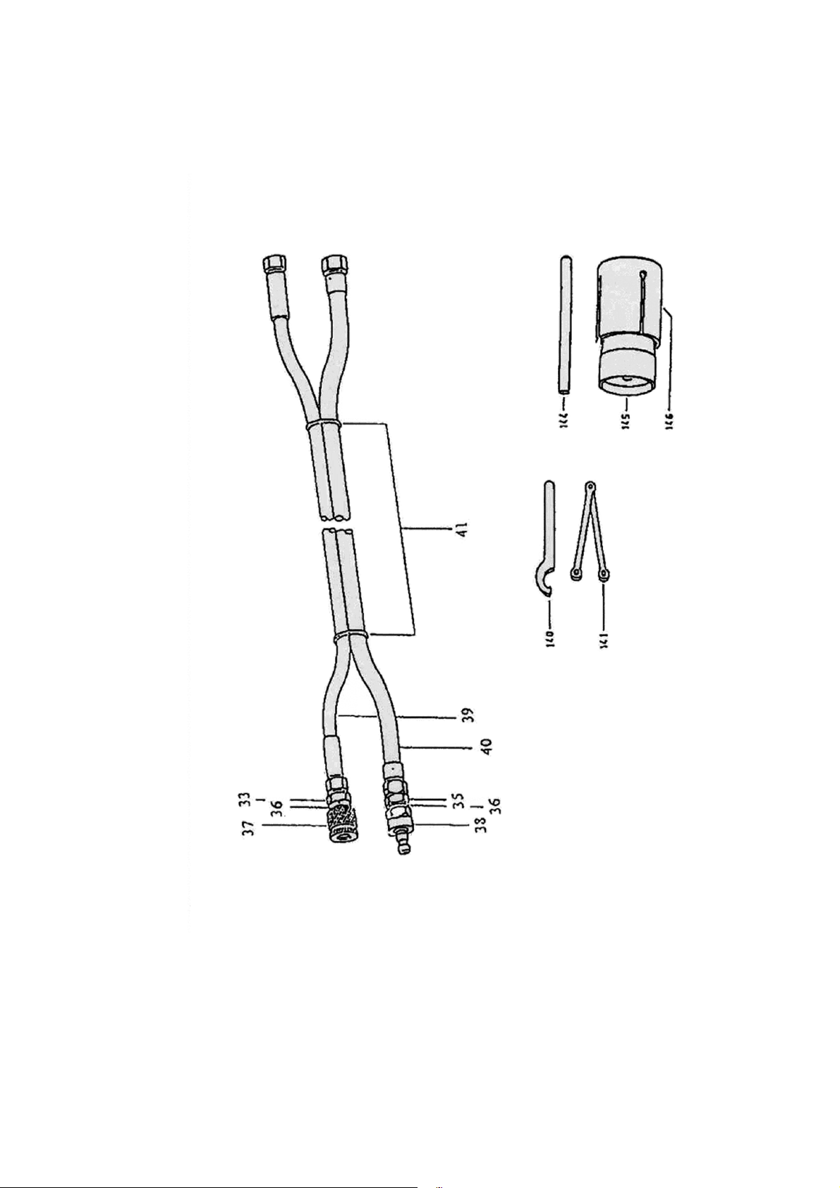
A.6 Explosion View of hose kit
Schmid & Wezel
D75433 Maulbronn,


 Loading...