


Betriebsanleitung/ Operating instructions
Wartungsanleitung/ Maintenance instructions
Ersatzteilliste/ Sparepart list
EFA VB 115
EFA VB 215
Viehbetäubungsgerät
Stunning Device
Wichtige Informationen:
Diese Anleitung unbedingt dem Bedienpersonal aushändigen!
Important Information:
Please forward these operating instructions to your operating
personell!
Schmid & Wezel
D 75433 Maulbronn
Ausführung/ Version
09.2016

INHALTSVERZEICHNIS
1. Verwendung, Lieferumfang, Zubehör....................................................................................2
1.1 Symbole in dieser Anleitung .........................................................................................................2
1.2 Bestimmungsgemäße Verwendung ...............................................................................................2
1.3 Lieferumfang ..............................................................................................................................2
1.4 Zubehör .....................................................................................................................................2
2. Sicherheitshinweise ...............................................................................................................2
2.1 Allgemeine Sicherheitshinweise ....................................................................................................2
2.2 Verhalten am Arbeitsplatz ............................................................................................................3
3. Inbetriebnahme und Betriebssicherheit ................................................................................3
3.1 Erstinbetriebnahme .....................................................................................................................3
3.2 Arbeiten mit dem Betäubungsgerät ..............................................................................................4
4. Montage........................................................................ .........................................................5
4.1 Austausch von Ersatzteilen...........................................................................................................5
4.2 Einstellung des Federzuges ..........................................................................................................6
5. Instandhaltung................................ ......................................................................................7
6. Reinigung ..............................................................................................................................9
6.1 Desinfektion und Reinigung während des Betriebs .........................................................................9
6.2 Tägliche Reinigung nach Beendigung der Schlachtung ...................................................................9
7. Wartung und Reparatur.........................................................................................................9
7.1 Wartung .....................................................................................................................................9
7.2 Reparaturen .............................................................................................................................10
7.3 Betäubungsgerät aufbewahren/lagern ........................................................................................10
8. Rücknahme von Altgeräten .................... .............................................................................10
A. Anhang / Appendix..... .........................................................................................................11
A.1 Bildanhang / Figure appendix.....................................................................................................11
A.2 Technische Daten / Technical Data.............................................................................................12
A.3 Liste der Ersatz- und Verschleißteile / Sparepart list.....................................................................13
A.4 Explosionszeichnung / Explosion Drawing EFA VB 115, EFA VB 215 ............................................16
A.5 Installationsplan / Installation plan .............................................................................................18
B. Konformitätserklärung...................................................................... ....... ............... ....... .....21
Schmid & Wezel
D 75433 Maulbronn
Seite/ Page
1
Ausführung/ Version
11.2011

1. Verwendung, Lieferumfang,
Zubehör
1.2 Bestimmungsgemäße
Verwendung
Hinweise, unbedingt lesen!
Diese Anleitung richtet sich an den Maschinenbediener. Bewahren Sie sie gut auf!
Das Betäubungsgerät wird mit Druckluft betrieben.
Das Viehbetäubungsgerät darf nur betrieben
werden:
in technisch einwandfreiem Zustand bestim-
mungsgemäß sowie sicherheits- und gefahrenbewußt.
mit allen angebauten Sicherheitseinrichtungen.
gemäß den Sicherheitshinweisen.
nachdem das Bedienpersonal diese Anleitung,
insbesondere Kapitel 2 "Sicherheitshinweise" (S.
2) und Kapitel 3 "Inbetriebnahme und Betriebssicherheit" (S. 3) gelesen und verstanden hat.
Nur so können Fehlbedienungen vermieden und Gefahrensituationen richtig eingeschätzt werden.
Das Gerät niemals auf Menschen
richten!
Greifen Sie niemals in den Bereich
des Kolbens, Sie könnten sich
sonst verletzen.
1.2.1 Einsatzgebiet
Das Viehbetäubungsgerät EFA VB 115 ist zum Betäuben von Kälbern mit einer Einschlagtiefe von
95 mm geeignet.
Das Viehbetäubungsgerät EFA VB 215 ist zum Betäuben von Rindern, Kühen und Bullen mit einer
Einschlagtiefe von 135 mm geeignet.
Die Maschine ist für eine andere Nutzung nicht ausgerüstet. Sollte eine anderweitige Nutzung vom Bediener gewünscht sein, bitte unbedingt vorher
Rücksprache mit der Firma Schmid & Wezel GmbH
& Co. (S&W) halten.
Bei allen anderen Anwendungen muss auf Unfallgefahr bzw. erhöhten Verschleiß hingewiesen werden.
Bei Zuwiderhandlung haftet allein der Benutzer.
1.2.2 Restgefahren
Da das Viehbetäubungsgerät für den industriellen
Einsatz an Tierkörpern vorgesehen ist, besteht die
Möglichkeit sich zu verletzen bzw. bei grobem
Missbrauch jemanden zu töten. Somit ist bei
missbräuchlichem Umgang mit der Möglichkeit des
direkten Todes bzw. des Todes durch Verbluten zu
rechnen. Deswegen muss immer auf den richtigen
Umgang mit der Maschine geachtet werden.
1.3 Lieferumfang
Tragen Sie beim Arbeiten einen
Gehörschutz!
1.1 Symbole in dieser Anleitung
Gefahrensymbol:
Hier ist äußerste Vorsicht und Umsicht
geboten. Bei Fehlverhalten besteht direkte Verletzungsgefahr für das Bedienpersonal oder Dritte. Außerdem kann die
Maschine Schaden nehmen.
Informationssymbol:
Mit diesem Symbol versehene Textpassagen geben Ihnen wichtige Informationen und nützliche Tipps.
Viehbetäubungsgerät EFA VB 115, bzw. EFA 215
Betriebsanleitung
1.4 Zubehör
Die Bestellnummern sowohl für im Lieferumfang
enthaltene Teile wie für Zubehör finden Sie in Anhang A.3 "Liste der Ersatz- und Verschleißteile /
Sparepart list" (S. 13).
2. Sicherheitshinweise
2.1 Allgemeine Sicherheitshinweise
Befolgen Sie beim Gebrauch des Viehbetäubungsgerätes unbedingt nachfolgende Sicherheitsmaßnahmen.
Für die Bedienung wird vorausgesetzt, dass das
Bedienpersonal ausreichende Kenntnisse zum
Arbeiten mit dem Viehbetäubungsgerät hat.
Einweisung durch unser Fachpersonal.
Schmid & Wezel
D 75433 Maulbronn
Seite/ Page
2/ 21
Ausführung/ Version
11.2011

Installations-, Wartungs-, und Reparaturarbei-
ten dürfen nur von autorisiertem Fachpersonal
durchgeführt werden.
Viehbetäubungsgeräte von Schmid & Wezel ent-
sprechen den einschlägigen Sicherheitsbestimmungen.
2.2 Verhalten am Arbeitsplatz
1. Halten Sie Ihren Arbeitsplatz in Ordnung.
Unordnung kann Unfälle zur Folge haben.
2. Berücksichtigen Sie Umgebungseinflüsse. Sorgen Sie für gute Beleuchtung (min. 500 Lux).
3. Halten Sie andere Personen von Ihrem Arbeitsplatz fern. Arbeiten Sie konzentriert und mit
Vernunft. Benutzen Sie das Viehbetäubungsgerät nicht, wenn Sie unkonzentriert und/oder
müde sind.
4. Bewahren Sie das Viehbetäubungsgerät sicher
auf. Unbenutzte Geräte an einem trockenen Ort
aufbewahren.
Wezel prüfen lassen.
Arbeitsplatz
Der Stellplatz für den Bediener sollte mindestens
1,5 qm groß sein. In diesen Bereich sollte kein anderer Arbeitsplatz hineinragen, da sonst auf Grund
der Bewegungen mit dem Viehbetäubungsgerät
Verletzungsgefahren entstehen könnten.
Die Beleuchtung des Arbeitsplatzes muss min. 500
Lux entsprechen.
3.1 Erstinbetriebnahme
Das Viehbetäubungsgerät nur im
ausgeschalteten Zustand an das
Betriebsnetz anschließen!
Wesentliche Informationen, z. B. technische Datenblätter, Zeichnungen und
Stücklisten finden Sie in Anhang A (S.
11).
5. Arbeitskleidung: Tragen Sie keine weite Kleidung oder Schmuck - diese können von beweglichen Teilen erfasst werden. Tragen Sie beim
Arbeiten festes Schuhwerk. Tragen Sie generell
ein Haarnetz!
6. Vermeiden Sie eine nicht normale Körperhaltung. Sorgen Sie für sicheren Stand und halten
Sie jederzeit das Gleichgewicht.
7. Pflegen Sie Ihre Werkzeuge mit Sorgfalt.
8. Lassen Sie keine Werkzeugschlüssel stecken.
Überprüfen Sie vor dem Einschalten, ob alle
Schlüssel entfernt sind.
9. Verwenden Sie nur EFA – Originalzubehör. Ein
Gebrauch anderer Einsatzwerkzeuge oder Zubehöre kann verletzungsgefährdend für Sie sein.
Bei Nicht-Verwendung von Original-Ersatzteilen
erlischt der Garantieanspruch.
10.Veränderungen und Umbauten an der Maschine
sind nicht zulässig und entbinden S&W von jeglicher Gewährleistung und Haftung.
3. Inbetriebnahme und
Betriebssicherheit
Prüfung der Schlagenergie
des Viehbetäubers
Die Prüfung ist nur mit dem Prüfgerät MEVB 100
möglich. Der Prüfzyklus muss nach Betriebsvorgaben erfolgen.
Das Gerät MEVB 100 alle 2 Jahre durch Schmid &
3.1.1 Federzug
Das Gerät muss immer in Kombination mit einer Gewichtsentlastung (Federzug) betrieben werden. Dabei sollte der Viehbetäuber über der Tötungsbucht
am Federzug plaziert werden. Bringen Sie den Federzug mit einer Schiebelaufkatze an einem höher
gelegenen Element über dem Arbeitplatz oder an
der Decke an. Informationen zur Feinabstimmung
des Federzuges finden Sie unter Kapitel 4.2 "Einstellung des Federzuges" (S. 6).
Das Viehbetäubungsgerät möglichst kopflastig aufhängen. Die Senkrechte kann bei Bedarf nach justiert werden.
Auf Grund des Gewichts von ca. 12 kg kann es beim
Befestigen oder Lösen der Gewichtsentlastung zu
einer Gefährdung durch Abrutschen oder Herunterfallen der Maschine kommen. Achten Sie auch darauf, dass sich die Maschine weder am
Karabinerhaken noch am Haken des Betäubungsgerätes verklemmt. Seien Sie umsichtig!
Wenn das Betäubungsgerät nicht benutzt wird, ist
dieses so abzulegen, dass es nicht zu unbeabsichtigtem Kontakt mit dem Gerät kommen kann.
3.1.2 Kompressor
Für den Betrieb des Betäubungsgerätes ist ein Kompressor vorgesehen (Bestell-Nr. siehe Ersatztelliste
Sonderzubehör).
3.1.3 Wartungseinheit
Siehe separate Bedienungsanleitung Kompressor
3.1.2.
Schmid & Wezel
D 75433 Maulbronn
Seite/ Page
3/ 21
Ausführung/ Version
11.2011

3.1.4 Anschluss d
es Viehbetäubungsgerätes
2-3 Tropfen Öl pro Minute
Installationsarbeiten dürfen nur
von autorisiertem Fachpersonal
durchgeführt werden.
Nehmen Sie den Druckluft-Anschluss nur bei ausgeschalteten
Geräten vor!
Vorgehensweise (siehe Installation des
Gerätes in Anhang A.5 "Installationsplan /
Installation plan" (S. 18))
Vor dem Anschließen:
1. Vor dem Anschließen des Gerätes prüfen, ob der
Abzugshebel und den Sicherungstaster frei und
leichtgängig sind (siehe Abb. 1).
Abzugshebel
Das Gerät ist gegen Überschreiten des
max. Betriebsdrucks von 12 bar durch
ein Sicherheitsventil abgesichert.
3.1.5 Abkuppeln des Viehbetäubungsgerätes
Beim Abkuppeln muss die Druckluftanlage drucklos sein.
Die Rändelhülse der Schnellkupplung (78)
zurückziehen und gegen den Anschlag halten.
Nach dem Entlüften der Druckkammern des
Gerätes, die Rändelhülse in Ausgangsstellung
bringen und Spiral-Druckschlauch abziehen.
3.2 Arbeiten mit dem
Betäubungsgerät
Erst nach vorherigem Lesen dieser
Bedienungsanleitung und nach
korrektem Anschluss darf das Betäubungsgerät verwendet werden!
Sicherungstaster
Abbildung 1: Abzugshebel und Sicherungstaster
Anschließen:
2. Betäubungsgerät mit dem Anschluss Sicherheits-Schnellkupplung (78) und Spiral-Druckschlauch (78 bis 82) an eine Wartungseinheit
(Sonderzubehör) anschließen.
3. Beim Ankuppeln des Gerätes muss der Betriebsdruck mind. 8 bar sein, da sonst das Auslöseventil (18) nicht schließt und Luft am
Auslöseventil austritt.
4. Zum Ankuppeln Rändelhülse der Schnellkupplung (78) zurückziehen, Schnellkupplung in
Schlauchstecktülle (70) einrasten lassen und
Rändelhülse loslassen.
5. Das Betäubungsgerät muss zum sicheren Arbeiten an einem Federzug ( Sonderzubehör) montiert werden.
6. Wartungseinheit in folgender Reihenfolge montieren: Wasserabscheider – Druckmanometer –
Öler.
Einstellen bei laufenden Gerät auf:
Greifen Sie bei angeschlossenem
Gerät niemals in den Bereich des
Kolbens!
Das Gerät niemals auf Menschen
richten!
Tragen Sie beim Arbeiten einen
Gehörschutz!
3.2.1 Arbeitsgang
Vorbereitung
Vor dem Einsatz sind die Betriebsdaten von Druckluftversorgung und Gerät auf Übereinstimmung zu
prüfen.
Vor Arbeitsbeginn ist außerdem zu prüfen ob,
1. der erforderliche Betriebsdruck von
- 12 bar bei Rindern, Kühen und Bullen
(VB 215)
Schmid & Wezel
D 75433 Maulbronn
Seite/ Page
4/ 21
Ausführung/ Version
11.2011

- 8 bar bei Kälbern (VB 115)
eingestellt ist.
2. das Betäubungsgerät funktionsfähig ist.
3. das Gerät dicht ist.
4. die allgemeinen Sicherheitshinweise Kapitel 2.1
"Allgemeine Sicherheitshinweise" (S. 2) berücksichtigt sind.
Nur mit einwandfreiem Gerät arbeiten, da sonst Unfallgefahr
besteht.
Nach erfolgtem Schuß Gerät sofort vom Tierkopf
abheben.
Gerät ist danach wieder betriebsbereit.
Rastet der Kolben (29) nicht selbstständig in der
Ausgangsstellung ein, muss nochmals ein Schuss
ohne Einsatz am Tier erfolgen.
Dazu Abzugshebel (23) am Handgriff und Zug-
stift an Bolzen (56) in Richtung Handgriff betäti-
gen.
Schuss erfolgt.
Nach dem Loslassen von Abzugshebel oder Zug-
stift geht der Kolben in die Ausgangsstellung.
Arbeiten
Abbildung 2: Betäubungspunkte
Das Gerät zum Betäuben auf den
Kopf des Tieres auflegen wie in
Abb. 2 gezeigt.
Das Gerät muss am Haltegriff und am Bügel (59) geführt werden.
Der Kopf des Bedienenden muss
dabei seitlich vom Gerät sein, um
bei eventuellem Rückschlag des
Betäubungsgerätes nicht verletzt
zu werden!
Abzughebel (23) am Handgriff betätigen und
Gerät auf den Tierkopf aufsetzen.
Sicherungstaster (55) löst Schuß aus.
Ein Arbeitsgang (Tierbetäubung)
ohne eingerasteten Kolben (29)
hat einen starken Rückschlag zur
Folge, d.h. Unfallgefahr!
3.2.2 Betriebssicherheit
Betäubungsgerät
Maschine sicher halten. Niemals einhändig
arbeiten.
im eingeschalteten Zustand besonders umsich-
tig handeln.
Niemals den Abzughebel betätigen, wenn das
Gerät nicht im Einsatz ist.
nach erfolgtem Schuss, das Gerät sofort vom
Tierkopf abheben.
zur sichereren Handhabung (Führung) sollte das
Betäubungsgerät an einem Federzug aufgehan-
gen werden.
4. Montage
Vor allen Montagearbeiten das Gerät vom Luftdrucknetz trennen!
Die zur Montage notwendigen Zeichnungen finden
Sie für die Maschine im Anhang A.1 "Bildanhang / Figure appendix" (S. 11).
4.1 Austausch von Ersatzteilen
Verwenden Sie nur EFA – Originalzubehör. Ein Gebrauch anderer Einsatzwerkzeuge oder Zubehöre
kann verletzungsgefährdend für Sie sein. Bei NichtVerwendung von Original-Ersatzteilen erlischt der
Garantieanspruch.
Schmid & Wezel
D 75433 Maulbronn
Seite/ Page
5/ 21
Ausführung/ Version
11.2011

Der Ersatzteilaustausch darf nur
von autorisiertem Fachpersonal
durchgeführt werden
Den Austausch von Ersatzteilen
nur durchführen, wenn das Gerät
vom Druckluft getrennt ist.
4.1.3 Austauschen des Gehäusedeckels (44)
Den Gehäusedeckel (44) auf Beschädigung
überprüfen und gegebenenfalls unbedingt austauschen (Unfallgefahr durch Druckeinwirkung)!
Den 0-Ring (44a) passend in Nut einlegen.
4 Schrauben (46) mit Sicherungsscheibe (45)
einschrauben, Anzugsmoment 10 Nm.
4.1.4 Austauschen des Auslöseventils (18)
Den Bolzen (56) ausschrauben, Spiral-
spannstift (25) zurückschlagen.
Auslöseventil herausziehen.
Wenn möglich sollten alle 4 Sechskantschrauben (74) nicht gelöst
werden, da diese mit genauem Anzugsmoment 67 Nm angezogen
sind.
4.1.1 Austausch des Kolbens (29)
Die Sechskant-Mutter (61) lösen, den Bügel
(58a) hochziehen und zur Seite schwenken.
Den Gehäusedeckel (44) abschrauben, Ventil-
einsatz (37) mit Raste (41) und Kolben herausziehen.
Beim Wiedereinbau des Kolbens, die 0-Ringe
einfetten oder ölen und ohne Kraftaufwand einführen.
Den Bügel (58a) möglichst eng an Gehäusedek-
kel (44) anlegen.
Anzugsmoment der Sechskant-Mutter (61) ist
40 Nm.
4.1.2 Austauschen des Puffers (49 bzw. 49a)
Den Kolben herausnehmen, wie in Kapitel 4.1.1
"Austausch des Kolbens (29)" (S. 6) beschrieben.
Den Nutring (42) mit 2 Schraubenziehern abhe-
ben.
Ventilschieber (35 und 36) und Zylinder (32)
nach oben herausziehen.
Beim Einbau den 0-Ring (14) im Gehäuse nicht
beschädigen. Keine Gewalt anwenden!
Eventuell die Zylinderstirnseite vor dem Einbau entgraten. Dabei den 0-Ring (14) einfetten und mit
schwächerer Zylinderseite vorzentrieren.
Die äußeren O-Ringe am Auslöseventil vor dem
Einbau einfetten oder ölen.
Auslösepunkt überprüfen.
(siehe Schnitt B-B, Anhang A, Seite 16).
4.1.5 Austauschen des Zylinderfußes (51)
4 Schrauben (74) ausschrauben und Zylinderfuß
durch leichte seitliche Schläge herausziehen.
Bei der Montage auf saubere Auflage der Auf-
hängung (58), auf den Zylinderfuß achten.
Je 2 Tellerfedern (73) gleichsinnig schichten und
die 4 Schrauben (74) mit Anzugsmoment 67 Nm
anziehen.
Achtung: Bei Nichteinhaltung des vorgeschriebenen Anzugsmomentes kann ein Ausreißen der Gewindeeinsätze im Gehäuse (1) eintreten.
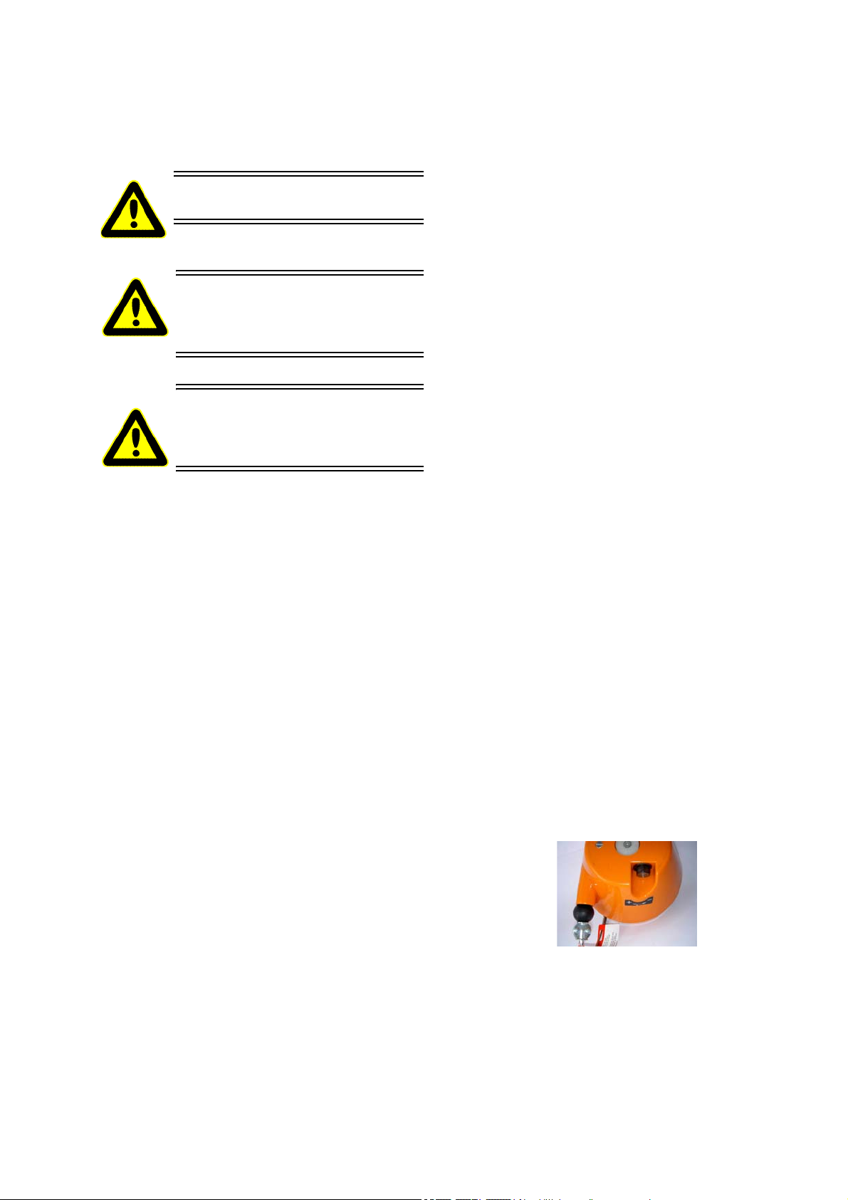
4.2 Einstellung des Federzuges
Die Feinabstimmung des Federzuges erfolgt über
die PLUS/MINUS-Schraube an seinem Gehäuse (siehe Abb. 3).
Abbildung 3: Federzug
drehen Sie dazu die Schraube in Richtung
MINUS bis sich das Gerät frei schwebend im
Gleichgewicht (mit der Zugfeder) auf Arbeitshöhe befindet.
Schmid & Wezel
D 75433 Maulbronn
Sollte kein Auszug möglich sein, ist der Federzug
blockiert und eine Neueinstellung ist notwendig:
drehen Sie die Schraube in Richtung PLUS bis
Seite/ Page
6/ 21
Ausführung/ Version
11.2011

ein Auszug möglich wird und beginnen Sie
erneut mit der Feineinstellung (siehe oben).
5. Instandhaltung
Während des Betriebes kann die Funktion gestört
sein, die Fehlerbehebung ist in den meisten Fällen
aber relativ einfach. In Tabelle 1: "Störungen und
ihre Behebung" sind diese Störungen mit möglichen Ursachen und resultierenden Behebungsmöglichkeiten aufgeführt.
Zur Behebung von Störungen das
Gerät unbedingt vom Druckluftschlauch trennen
Alle Arbeiten nur durch qualifiziertes, eingewiesenes Fachpersonal
durchführen lassen.
Schmid & Wezel
D 75433 Maulbronn
Seite/ Page
7/ 21
Ausführung/ Version
11.2011

Tabelle 1: Störung
Störung mögliche Ursache Behebung
en und ihre Behebung
1. Druck entweicht aus Entlüftungsschlitz
2. Druck entweicht aus Auslöseventil (18) (leichtes Blasen
zulässig)
3. Kolben (29) geht nicht vollständig zurück
4. Leerschüsse Kolben bleibt hängen. Leichtgängigkeit des Kolbens prü-
Einer der 0-Ringe (14, 33, 34, 39,
43) ist beschädigt oder durch
Fremdkörper verschmutzt.
Laufflächen des Ventilschiebers
(36) sind beschädigt.
Auslöseventil defekt Auslöseventil austauschen, siehe
Gerät zu schwach oder zu kurz
aufgesetzt.
Wichtige Teile (18, 35, 36, 55)
ohne Schmierung.
Einer der 0-Ringe (14,31) ist
abgenützt oder beschädigt.
Auslöseventil defekt. Auslöseventil austauschen, siehe
0-Ringe reinigen oder ersetzen.
Laufflächen polieren oder Ventilschieber austauschen.
Kapitel 4.1.4 "Austauschen des
Auslöseventils (18)" (S. 6).
Nach dem Wechseln des Auslöseventils Auslösepunkt neu einstellen, siehe Anhang A.1.2 (S. 11).
Gerät betonter aufsetzen.
fen und Klemmstellen beseitigen.
Teile reinigen und durchschmieren.
0-Ringe austauschen.
Kapitel 4.1.4 "Austauschen des
Auslöseventils (18)" (S. 6).
5. Zu geringe Schussleistung Luftdruck zu nieder. Richtige Druckeinstellung.
Auslösepunkt falsch eingestellt. Auslösepunkt neu einstellen,
Anhang A.1.2 (S. 11).
Auslöseventil defekt. Auslöseventil austauschen, siehe
Kapitel 4.1.4 "Austauschen des
Auslöseventils (18)" (S. 6)
Mangelnde Schmierung. Öl-Einstellung siehe Kapitel 3.1
"Erstinbetriebnahme" (S. 3)
6. Zu geringe oder keine Rückhubkraft
Einer der 0-Ringe (14, 33, 34) ist
beschädigt.
Raste (41) beschädigt. Raste austauschen.
Einer der 0-Ringe (31, 50) ist
beschädigt.
Manschette (15) undicht oder
falsch montiert.
0-Ringe austauschen.
0-Ringe austauschen.
Manschette richtig montieren
(Stellung der Arretieraussparung
in der Manschette in Arretiernase
im Gehäuse).
Manschette austauschen.
Schmid & Wezel
D 75433 Maulbronn
Puffer (49, 49a) beschädigt, zerschlissen.
Seite/ Page
8/ 21
austauschen.
Ausführung/ Version
11.2011

6. Reinigung
Nehmen Sie Reinigungsarbeiten
nur bei vom Druckluftnetz getrenntem Betäubungsgerät vor.
Reinigen Sie das Gerät in heißen
Wasser mit einen Lappen oder
Schwamm.
Beachten Sie die Sicherheits- und
Hygieneanforderungen (DIN EN
1672).
Nach § 3 Abs. 2 Tierschutz-Schlachtverordnung ist
die Anlage für das Betäuben der Tiere so instand zu
halten, dass ein rasches und wirksames Betäuben
und Schlachten möglich ist.
6.2.1 Reinigung des Betäubungsgerätes
1. Bringen Sie das Betäubungsgerät zu Ihrer Werkzeugstelle (Werkstatt).
2. Entfernen Sie groben Schmutz mit einer Bürste
und warmen Wasser (ca. 45...55°C); ggf. hartnäckige oder verkrustete Verschmutzungen einweichen.
3. Geben Sie das Reinigungsmittel in warmes Wasser. Verteilen Sie den Schaum auf den zu reinigenden Flächen und lassen Sie das
Reinigungsmittel 15...20 Minuten einwirken.
4. Waschen Sie den gelösten Schmutz mit warmen
Wasser ab.
5. Das komplette Betäubungsgerät mit sauberen
Wasser abwaschen und abtrocken.
Empfohlene Reinigungsmittel
Diversey Lever Tego 2000: Oberflächenaktives
Desinfektionsmittel
Diversey Lever GmbH
Mallaufstr. 50-56, 68219 Mannheim
6.1 Desinfektion und Reinigung
während des Betriebs
Nach Vorgaben der EU sind im Rahmen der Sorgfalts- und Eigenkontrollpflichten der für die Geräte
verantwortlichen Personen auch entsprechende Dokumentationen über durchgeführte Reinigungen
und Wartungen mittels Reinigungsplänen erforderlich.
6.2 Tägliche Reinigung nach
Beendigung der Schlachtung
Ein störungsfreier Dauerbetrieb ist nur dann gewährleistet, wenn das Betäubungsgerät ständig hygienisch einwandfrei sauber gehalten wird.
Üblicherweise sollte das Gerät vor jeder Reinigung
desinfiziert werden. Dabei muss eine mindestens
tägliche Reinigung und Wartung an den einzelnen
Schlachttagen, sowie eine zusätzliche Reinigung
nach Bedarf bei erkennbaren Verunreinigungen erfolgen.
Beachten Sie dazu die geltenden Sicherheits- und
Hygieneanforderungen (DIN EN 1672)!
Alternativ:
P3-topax 91: Oberflächenaktives Desinfektionsmittel
Henkel-Ecolab Deutschland GmbH
Postfach 13 04 06, 40554 Düsseldorfein
Reinigungsplan und weitere Einzelheiten erhalten
Sie unter o. g. Firmenadressen
Die o.g. Reinigungsmittel sind nur eine Empfehlung;
bei der Verwendung von anderen Reinigungsmittel
muss die Materialverträglichkeit und Hygienevorschriften kundenseitig geprüft werden.
7. Wartung und Reparatur
7.1 Wartung
Wartungsarbeiten dürfen nur von
autorisiertem Fachpersonal durchgeführt werden.
Schalten Sie das Betäubunsgerät
vor Wartungsarbeiten immer aus
und trennen Sie es vom Druckluftnetz.
Keine scharfen Lösungsmittel zusetzen! Keinen Dampf- bzw. Hochdruckstrahler verwenden! Gerät
nicht in Wasser tauchen!
Schmid & Wezel
D 75433 Maulbronn
7.1.1 Vor und während der Schlachtung:
Für einen störungsfreien Betrieb ist bei der
Seite/ Page
9/ 21
Druckluftzuruhr unbedingt eine Wartungseinheit
Ausführung/ Version
11.2011

R 3/8" mit Filter, Regler und Öler zu verwenden
(im Kompressor enthalten).
Verwenden Sie nur säurefreies Markenöl mit
einer (Best.-Nr. 001 365 612).
Ölereinstellung:
bei ca. 15 Schüssen 1 Tropfen Öl.
7.2 R eparaturen
Reparaturen dürfen nur von autorisiertem Fachpersonal vorgenommen werden.
Regelmäßig kontrollieren, ob genügend Öl im
Vorratsbehälter ist.
Kondensat im Wasserabscheider regelmäßig
ablassen.
7.1.2 Nach der Schlachtung
Nach Beendigung der Schlachtung, das Gerät
abkuppeln (siehe Kapitel 3.1.5 "Abkuppeln des
Viehbetäubungsgerätes" (S. 4).
Die beweglichen Teile (Auslöseventil (18), Siche-
rungstaster (55) und Wippe (22), siehe Anhang
A.1.1 (S. 11) und Anhang A.1.2 (S. 11)) einölen
und auf Leichtgängigkeit überprüfen.
Achtung! Kein Wasser in die Entlüftungsschlitze
(siehe Anhang A.1.1 (S. 11)) bringen.
7.1.3 Verschleiß
Die Puffer (49 und 49a) nach ca. 50.000
Arbeitsgängen überprüfen und bei Beschädigung auswechseln!
7.1.4 Druckluftmotor und Getriebe
Alle 3 Monate, jedoch min. 4 x pro Jahr kpl. rei-
nigen und verschlissene und / oder defekte Teile
austauschen.
Schalten Sie das Betäubungsgerät
vor Reparaturarbeiten immer aus
und trennen Sie es vom Druckluftnetz.
Verwenden Sie nur Original-Ersatzteile
Hinweise:
Ersatzteillisten finden Sie im Anhang A.3
(S. 13).
Auf Wunsch können für Reparatur-Fachwerkstätten Ersatzteillisten nachgereicht
werden.
7.3 Betäubungsgerät aufbewahren/
lagern
Lagern Sie das Betäubungsgerät immer in trockenen Räumen.
7.1.5 Wartungseinheit
in regelmäßigen Abständen, jedoch min. 2 x pro
Monat überprüfen, das Kondenswasser entfernen und Spezialöl nachfüllen.
Spezialöl für Wartungsanlage:
EFA-Spezialöl 0,5 l Art. Nr. 001 365 611
EFA-Spezialöl 5,0 l Art. Nr. 001 365 612
Spezialöl für Kompressor:
EFA-Spezialöl 1,0 l Art. Nr. 001 365 637
EFA-Spezialöl 5,0 l Art. Nr. 001 365 636
Schmid & Wezel
D 75433 Maulbronn
Seite/ Page
8. Rücknahme von Altgeräten
Geben Sie Altgeräte zum Entsorgen an das Stammhaus zurück.
Ausführung/ Version
10/ 21
11.2011

A. Anhang / Appendix
A.1 Bildanhang / Figure appendix
A.1.1 Abbildung A / Figure A
Bügel / hoop (59)
Entlüftungsschlitze / vent slots
Handgriff / handle
Abzugshebel / trigger lever (23)
Zugstift / drawpin
A.1.2 Einzelheiten Abbildung B / Blowup Figure B
Bolzen / bolts (56)
Sicherungstaster / safety contact
switch (55)
Kolben / plunger (29)
Einstellung des Auslösepunktes am Auslöseventil (18) mit SechskantSchraube (17) am Abzugshebel (23).
Adjustment of the trigger point on the trip valve (18) with hexagonal
screw (17) on the trigger lever (23).
Ca. 2 Umdrehungen bei 12 bar Betriebsdruck und nicht eingedrücktem Sicherungstaster.
1,5
Approx. 2 turns at 12 bar operational pressure and safety contact
switch in released position.
Schmid & Wezel
D 75433 Maulbronn
Seite/ Page
11/ 21
Auslöseventil / trip valve (18)
Wippe / rocker (22)
Bolzen / bolts (56)
Ausführung/ Version
11.2011

A.2 Technische Daten / Technical Data
EFA VB 115 EFA VB 215
Betriebsdruck operational pressure 8 bar 12 bar
Luftverbrauch air consumption 8 l pro Schuß bei 8 bar
8 l per shot at 8 bar
Druckluftanschluß compressed air con-
nection
Schlagbolzen firing pin Ø 12 x 95 mm
Abmessung length 320 x 230 x 380 mm 360 x 230 x 380 mm
Gewicht weight 12 kg 12 kg
R 3/8“ R 3/8“
(Wirklänge)
(effective lenght)
12 l pro Schuß bei 12 bar
12 l per shot at 12 bar
Ø 12 x 135 mm
(Wirklänge)
(effective lenght)
Schmid & Wezel
D 75433 Maulbronn
Seite/ Page
12/ 21
Ausführung/ Version
11.2011

A.3 Liste der Ersatz- und Verschleißteile / Sparepart list
EFA VB 115 EFA VB 215
Bild-
Nr.
Pos.
1 1 Gehäuse Housing 001 963 918 001 963 918
5 2 Verschlußschraube Locking screw 001 963 986 001 963 986
6 1 Dichtring Sealing ring 001 963 916 001963 916
7 1 O-Ring O-ring 001 312 675 001 312 675
8 1 Sperrkolben Lock plunger 001 963 906 001 963 906
9 1 O-Ring O-ring 001 312 674 001 312 674
10 1 Druckfeder Pressure spring 001 963 908 001 963 908
11 1 O-Ring O-Ring 001 312 627 001 312 627
12 1 Ventileinsatz Valve insert 001 963 905 001 963 905
13 1 Reduziernippel Reducing nipple 003 005 688 003 005 688
Stück
Pcs.
Benennung Designation Best.-Nr.
Viehbetäubungsgerät
komplett
Stunning device complete
Best.-Nr.
Order-No.
130 109 510 130 109 610
Order-No.
14 1 O-Ring O-ring 001 312 676 001 312 676
15 1 Manschette Sleeve 001 963 907 001 963 907
16 1 Sechskantmutter Hexagonal nut 001 300 303 001 300 303
17 1 Sechskantschraube Hexagonal nut 001 320 132 001 320 132
18 1 Auslöseventil kpl.
(Nr. 19-24)
19 1 O-Ring O-ring 001 317 721 001 317 721
19a 1 O-Ring O-ring 001 312 601 001 312 601
20 1 Lager Bearing 001 963 946 001 963 946
21 1 Spiralspannstift Spiral tension pin 001 963 953 001 963 953
22 1 Wippe Rocker 001 963 945 001 963 945
23 1 Abzughebel Trigger lever 001 963 950 001 963 950
24 1 Spiralspannstift Spiral tension pin 001 963 952 001 963 952
25 1 Spiralspannstift Spiral tension pin 001 963 966 001 963 966
27 1 Schalldämpfer Silencer 001 963 932 001 963 932
Trip valve complete
(No. 19-24)
001 963 942 001 963 942
29 1 Kolben komplett
(Nr. 29a-31)
29a 1 Hülse Casing 003 009 406 003 009 406
29b 1 Kolben Plunger 003 009 407 003 009 407
Schmid & Wezel
D 75433 Maulbronn
Plunger complete
(No. 29a-31)
Seite/ Page
13/ 21
008 009 73
7 008 009 736
Ausführung/ Version
11.2011

29c 1 Scheibe Disk 003 009 405 003 009 405
29d 1 Stößel (geschlossen) Tappet (closed) 003 009 734 003 009 735
31 1 O-Ring O-ring 001 312 677 001 312 677
32 1 Zylinder Cylinder 001 963 933 001 963 983
33 2 O-Ring O-ring 001 312 679 001 312 679
34 1 O-Ring O-ring 001 312 678 001 312 678
35 1 Ventilschieber, Unterteil Valve slide,
botton element
36 1 Ventilschieber, Oberteil Valve slide, top element 001 963 928 001 963 984
37 1 Ventileinsatz komplett
(Nr. 38-40)
38 1 O-Ring O-ring 001 312 682 001 312 682
39 2 O-Ring O-ring 001 312 681 001 312 681
40 1 Ventileinsatz Valve insert 003 009 090 003 009 090
41 1 Raste Stop 001 963 926 001 963 926
42 1 Nutring Groove ring 003 014 239 003 014 239
43 1 O-Ring O-Ring 001 312 680 001 312 680
44 1 Gehäusedeckel komplett
(mit Nr. 44a)
44a 1 O-Ring O-Ring 001 312 686 001 312 686
45 4 Sicherungsscheiben Lock washer 001 963 965 001 963 965
46 4 Zylinderschraube Cylinder screws 001 320 218 001 320 218
Valve insert complete
(No. 38-40)
Housing cover complete
(with No. 44a)
001 963 941 001 963 941
001 963 937 001 963 937
001 963 921 001 963 985
47 1 Luftabweiser Air defelctor 001 963 987 001 963 987
48 1 Buchse Sleeve 001 963 934 001 963 934
49 1 Puffer Buffer 001 963 988 001 963 988
49a 1 Puffer Buffer 001 963 935 001 963 935
50 O-Ring O-Ring
51 1 Zylinderf
54 1 Druckfeder Pressure spring 001 362 629 001 362 629
55 1 Sicherungstaster Safety contact switch 007 009 391 007 009 391
56 1 Bolzen, vollständig Bolt, complete 007 004 990 007 004 990
57 1 Sechskantmutter Hexagonal nut 001 304 503 001 304 503
58 1 Aufhängung, vollständig Support, complete 007 005 622 007 005 622
58a 1 Bügel Hoop 003 008 050 003 008 049
59 1 Bügel, vollständig Hoop, complete 007 005 623 007 005 623
60 2 Sechskantschraube Hexagonal screw 003 005 567 003 005 567
uß, vollständig Cylinder foot, complete 007 009 402 007 009 402
001 312 683 001 312 683
Schmid & Wezel
D 75433 Maulbronn
Seite/ Page
14/ 21
Ausführung/ Version
09.2016

61 2 Sechskantmutter Hexagonal nut 001 304 505 001 304 505
73 8 Tellerfeder Plate spring 001 315 906 001 315 906
74 4 Sechskantschraube Hexagonal screw 002 000 233 002 000 233
75 1 Hinweisschild Information plate 003 005 632 003 005 632
76 4 Halbrundkerbnagel Half round notched nail 001 306 504 001 306 504
Sonderzubehör Special accessories
62 1 Schlauch vst. (Nr. 63-67) Hose reinforced
(No. 63-67)
63 1 Druckschlauch vst. Compressor hose
reinforced
64 1 Bolzen Bolt 003 005 621 003 005 621
65 1 Druckschlauch vst. Compressor hose
complete
66 3 Dichtring Sealing ring 001 313 241 001 313 241
67 1 Hohlschraube Banjo bolt 001 610 627 001 610 627
68 1 Spiral-Druckschlauch vst.
(Nr. 78-80)
78 1 Einhandkupplung Rapid action coupling 001 366 715 001 366 715
79 1 Spiral-Druckschlauch Spiral compressor hose 001 372 106 001 372 106
80 1 Stecknippel Fitting 001 367 712 001 367 712
Kompressor 400 V Compressor 400 V 001 606 885 001 606 885
Kompressor 230 V
Wechselstrom
Spiral compressor hose
reinforced (No. 78-80)
Compressor 223 V AC 001 606 886 001 606 886
007 009 412 007 009 412
007 005 624 007 005 624
001 366 927 001 366 927
001 366 926 001 336 926
Kolben kpl. mit Luftkanal Plunger comp. with air
Stößel vst. mit Luftkanal Tappet comp. with air
Wartungseinheit Airfilter regulator 001 367 045 001 367 045
Messgerät MEVB 100 Measuring instrument
Ring VB 115/215 für
MEVB 100
Federzug Spring-loaded hoist 001 620 032 001 620 032
Spezialöl 5 Liter Special oil 5 liters 001 365 612 001 365 612
Dichtungssatz kpl. beste-
hend aus
Schmid & Wezel
D 75433 Maulbronn
canal
canal
MEVB 100
Ring VB 115/215 for
MEVB 100
Complete set of seals
consist of
Seite/ Page
15/ 21
008 009 409 008 009 408
007 009 403 007 009 404
008 011 633 008 011 633
003 011 372 003 011 372
007 899 497 007 899 497
Ausführung/ Version
11.2011

A.4 Explosionszeichnung / Explosion Drawing EFA VB 115, EFA VB 215
Schmid & Wezel
D 75433 Maulbronn
Seite/ Page
16/ 21
Ausführung/ Version
09.2016

Sonderzubehör / Special accessories
Schlauch vst. Best.-Nr. 007 009 412
Hose compl. Order No. 007 009 412
Spiral-Druckschlauch Best.-Nr. 001 366 926
Spiral air hose Order No. 001 366 926
Schmid & Wezel
D 75433 Maulbronn
Seite/ Page
17/ 21
Ausführung/ Version
11.2011

A.5 Installationsplan / Installation plan
Kompressor / Compressor
2 Manometer/ Manometer
3 Sicherheitsventil / Safety valve
4 Druckschalter / Pressure switch
5 Kondensatablaß / Condensate drain
6 Druckluftausgang / Air outlet
8 Kombiwartungseinheit / Servicing unit
9 Kompressoraggregat / Compressor aggregate
10 Druckluftkessel / Air receiver
Artikel-Nr. Order no. 001 606 885 001 606 886
Spannung/Frequenz Voltage/Frequency 230/400V 50Hz ~ 230V 50 Hz
Stromaufnahme Current 7,2/4,4 A 11,0 A
Isolierklasse Insulation class F F
Leistung Power 1800W 1800W
Umdrehung Rotation 1400 U/min 1400 U/min
Bauart Build 2-stufig / 2-stufig 2-stufig / 2-stufig
Zylinder Cylinder 2 2
Ansaugleistung Luft Suction capacity 160 l/min 160 l/min
Max. Druck Max. pressure 15 bar 15 bar
Behälterinhalt Tank capacity 6 l 6 l
Schutzart Protection P54 P54
Schallpegel Sound level 76 dzB(A) 76 dzB(A)
Gewicht Weight 25 kg 25 kg
Abmaße LxBxH Dimension 550x470x420 mm 550x470x420 mm
Schmid & Wezel
D 75433 Maulbronn
Seite/ Page
18/ 21
Ausführung/ Version
11.2011

alternativ
zentrale
Druckluftanlage
Federzug über
vorderem Drittel
der Tötungsbucht plazieren.
Kompressor
Spiralschlauch
Der elektrische Anschluss
muss mit Steckdose und
Hauptschalter nach den
örtlichen Bestimmungen
erfolgen.
2000 mm
Schmid & Wezel
D 75433 Maulbronn
Vord. Drittel
Tötungsbucht Oberkante
200 mm
Seite/ Page
19/ 21
Ausführung/ Version
11.2011

alternative
safety valve
maintenance unit
Place spring balancer
hoist over front third
slaughter bay.
spiral hose
compressor
The electrical connection
to the receptacle and main
switch must be made in
accordance with local regulations.
2000 mm
Schmid & Wezel
D 75433 Maulbronn
front third
top edge of slaughter bay
200 mm
Seite/ Page
20/ 21
Ausführung/ Version
11.2011

B. Konformitätserklärung
EG-KONFORMITÄTSERKLÄRUNG
EC DECLARATION OF CONFORMITY
Hiermit erklären wir, dass die nachfolgend bezeichneten vollständigen Maschinen aufgrund ihrer Konzipierung und Bauart der
EG-Maschinenrichtlinie 98/37/EG und den grundlegenden Sicherheits- und Gesundheitsanforderungen entsprechen.
Bei einer nicht mit uns abgestimmten Änderung der Maschine verliert diese Erklärung ihre Gültigkeit.
We hereby declare that the following designated complete machines comply with the EC machine directive 98/37/EC and meet
the essential demands on health and safety on account of their conception and design.
The validity of this declaration expires when a modification to the machine is made without being coordinated with us.
CE
Bezeichnung der Maschine: Viehbetäubungsgerät
Typ EFA VB 115,VB 125, VB 130, VB 215, VB 225, VB 230, VB 235,VB512
Antrieb Pneumatikantrieb
Angewandte Vorschriften/Richtlinien: 98/37/EG
Angewandte A- Normen: DIN EN 1050
Angewandte B- Normen: DIN EN 294, DIN EN 954-1, DIN EN 954-2(Entwurf)
Angewandte C- Normen: --------Angewandte nationale Normen: ---------
Machine identification: Livestock stunning device
Type EFA VB 115,VB 125, VB 130, VB 215, VB 225, VB 230, VB 235,VB512
Actuation Pneumatic drive
Applied regulations/directives: 98/37/CE
Applied A- standards: DIN EN 1050
Applied B- standards: DIN EN 294, DIN EN 954-1, DIN EN 954-2(draft)
Applied C- standards: --------Applied national standards: ---------
Hersteller Name - Anschrift: Schmid & Wezel GmbH & Co
Manufacturer Name - Address: Maybachstrasse 2 , 75433 Maulbronn
Unterschrift: Signature: __________________________________________
Firma: Firma: Ulrich Merkle Dr. Norbert Lay
Angaben zum Unterzeichner: Geschäftsführer Leiter Technik und Entwickelung
Details of the undersigned: Managing director Head of engineering and development
Schmid & Wezel
D 75433 Maulbronn
Seite/ Page
21/ 21
21
Ausführung/ Version
11.2011

Operating instructions / Betriebsanleitung
Maintenance instructions / Wartungsanleitung
Sparepart list / Ersatzteilliste
EFA VB 115
EFA VB 215
Stunning Device
Viehbetäubungsgerät
Important Information:
Please forward these operating instructions to your operating
personell!
Wichtige Informationen:
Diese Anleitung unbedingt dem Bedienpersonal aushändigen!
Schmid & Wezel
D 75433 Maulbronn
Version / Ausführung
11.2011

TABLE OF CONTENTS
1. Application, scope of delivery and accessories......................................................................2
1.1 Symbols used in this manual ........................................................................................................2
1.2 Proper use..................................................................................................................................2
1.3 Scope of delivery.........................................................................................................................2
1.4 Accessories.................................................................................................................................2
2. Safety instructions.................... .............................................................................................2
2.1 General safety instructions...........................................................................................................2
2.2 Workplace safety.........................................................................................................................3
3. Commissioning and operational safety .................................................................................3
3.1 Commissioning............................................................................................................................3
3.2 Working with the stunning device.................................................................................................4
4. Installation and assembly .....................................................................................................5
4.1 Replacement of spare parts .........................................................................................................5
4.2 Adjusting the spring-loaded pulley................................................................................................6
5. Maintenance ............................................................................... ...........................................7
6. Cleaning ................................................................................................................................9
6.1 Disinfection and cleaning during operation ....................................................................................9
6.2 Daily cleaning at shift end............................................................................................................9
7. Repair and maintenance........................................................................................................9
7.1 Maintenance ...............................................................................................................................9
7.2 Repair ......................................................................................................................................10
7.3 Storage of stunning device.........................................................................................................10
8. Return of decommissioned equipment................................................................................10
A. Anhang / Appendix..... .........................................................................................................11
A.1 Bildanhang / Figure appendix.....................................................................................................11
A.2 Technische Daten / Technical Data.............................................................................................12
A.3 Liste der Ersatz- und Verschleißteile / Sparepart list.....................................................................13
A.4 Explosionszeichnung / Explosion Drawing EFA VB 115, EFA VB 215 ............................................16
A.5 Installationsplan / Installation plan .............................................................................................18
B. Declaration of conformity....................................................................................................21
Schmid & Wezel
D 75433 Maulbronn
Page / Seite
1
Version / Ausführung
11.2011

1. Application, scope of delivery
and accessories
1.2 Proper use
1.2.1 Application
Important notes!
This manual has been specifically compiled for
machine operators. Keep it near the machine for
future reference!
The stunning device is powered by compressed air.
The stunning device may only be operated
for the intended purpose, with due care as
regards safety, and if the equipment is in proper
working order
if all safety devices are properly mounted
according to the safety instructions in this manual
after instruction of the operating personnel, who
must also have read and understood the
instructions in chapter 2 "Safety instructions"
(page 2) and chapter 3 "Commissioning and
operational safety" (page 3).
This is necessary in order to prevent incorrect
operation and to enable operators to assess potential
risks accurately.
Never point the device towards a
person!
The EFA VB 115 stunning device is suitable for the
stunning of calves with an impact depth of 95 mm.
The EFA VB 215 stunning device is suitable for the
stunning of heifers, cows and bulls with an impact
depth of 135 mm.
The machine is not designed for any other use. If
you wish to use the equipment for other purposes,
first consult Schmid & Wezel GmbH & Co (S&W).
If the machine is used for any other purposes,
please note that there is a greater risk of serious
injury and increased wear to machine parts. The
operator shall be solely liable for any damage arising
from improper use of the equipment.
1.2.2 Residual risks
As the stunning device is designed for the industrial
processing of animals, there is a risk of serious
injury to persons, if it is not handled with the
necessary caution. If handled improperly or without
due care, persons might even be killed instantly, or
die as a consequence of serious blood loss. It is
therefore imperative that the stunning device is
handled properly and according to the instructions
in this manual.
Never reach into the operating
area of the piston, as this could
lead to injury.
When working with the stunning
device, always wear hearing
protection!
1.1 Symbols used in this manual
Danger:
Proceed with extreme caution. In the
event of incorrect operation, there is a
risk of injury to operating staff and other
persons. There is also a risk of damage
to the machine.
Information:
This symbol highlights sections in the
text containing important information
and useful hints.
1.3 Scope of delivery
Stunning devices EFA VB 115 or EFA VB 215
Operating manual
1.4 Accessories
For order numbers of standard equipment and
accessories, please refer to Appendix A.3 "Sparepart
list" (page 13).
2. Safety instructions
2.1 General safety instructions
When operating the stunning device, always
adhere to the following safety instructions:
Only personnel who have been properly trained
and instructed in the safe use of the stunning
device may operate the machine.
Instruction by our specialist technicians
Installation, maintenance and repair work may
only be carried out by suitably trained and
authorised specialist technicians.
Schmid & Wezel
D 75433 Maulbronn
Page / Seite
2 / 21
Version / Ausführung
11.2011

Stunning devices by Schmid &Wezel conform to
all relevant safety standards
2.2 Workplace safety
1. Keep your workplace tidy.
2. Ensure that the workplace environment is
suitable for the use of the tool and properly
illuminated (min. 500 lx).
3. Prevent unauthorised persons from accessing
your workplace. Concentrate on your work and
use common sense. Do not handle the stunning
device, if you feel tired and/or find it difficult to
concentrate.
4. Keep the stunning device in a safe place. While
not in use, store it in a dry place.
5. Work clothing: Do not wear loose clothing or
jewellery, as such items could become
entangled in moving machine parts. Wear safety
footwear. Always wear a hairnet!
6. Avoid an unnatural posture. Make sure that you
stand firmly and do not lose your balance.
7. Handle your tools with care.
8. Never leave spanners or wrenches attached to
the tool. Before starting it, inspect the stunning
device to ensure that all spanners and wrenches
have been removed.
9. Use only original EFA accessories. If other tool
inserts or accessories are used, there is also an
increased risk of injury to the operator and
other persons. The use of spare parts other
than original Schmid & Wezel parts shall void all
warranty.
10.It is prohibited to modify the machine in any
way. Schmid & Wezel rejects any liability for
damages arising from modified equipment.
3. Commissioning and
operational safety
Testing of impact energy
of the stunning device
This test can only be performed with the MEVB 100
testing unit. For details regarding the testing cycle,
see operating instructions.
Have the MEVB 100 unit checked every 2 years by
Schmid & Wezel.
Workplace
device is moved during operation and could injure
other persons.
The working area must be illuminated with min.
500 lx.
3.1 Commissioning
Ensure that the stunning device
is switched off and connect it to
the supply network!
For detailed information, technical
data, parts lists and drawings of the
equipment, see Appendix A (page 11).
3.1.1 Spring-loaded pulley
The device may only operated in conjunction with a
spring-loaded pulley. The stunning device should
thereby be attached to the pulley mechanism and
positioned above the killing bay. The pulley must be
attached to a sliding crab secured to a beam above
the workplace or the ceiling. For detailed
information on how to install and balance the
spring-loaded pulley, please refer to chapter 4.2
"Adjusting the spring-loaded pulley" (page 6).
The stunning device must be attached in such a way
that its head section faces downwards. If required,
the tool can be realigned in vertical direction.
As the device weighs about 12 kg, there is a risk of
injury if it is dropped while being attached or
removed from the pulley system. Ensure that the
stunning device is not jammed at the hooks. Always
proceed with special care when attaching or
removing the device from the pulley.
When the stunning device is not used, it must be
stored in such a way that persons cannot
inadvertently come into contact with it.
3.1.2 Compressor
The stunning device must be operated in
conjunction with a compressor (for order no., see
list of accessories).
3.1.3 Maintenance unit
For details, see separate compressor operating
manual (3.1.2).
The working area for the operator must be at least
1.5 m². This area must be kept clear and may not
be shared with any other staff, as the stunning
Schmid & Wezel
D 75433 Maulbronn
Page / Seite
3 / 21
Version / Ausführung
11.2011

3.1.4 Conn
ecting the stunning device
All installation work must be
carried out by suitably trained and
authorised technicians.
Before connecting the stunning
device to the compressed air
supply line, switch it off!
While the machine is running, adjust the
following parameter settings:
2-3 drops of oil per minute
The stunning device is protected by a
safety valve against overpressures
exceeding the maximum operating
pressure of 12 bar.
3.1.5 Disconnecting the stunning device
Connecting procedure (see instructions for
the installation of the device in Anhang A.5
"Installationsplan / Installation plan" (S.
18)).
Before connecting the stunning device:
1. Check whether the release lever and the safety
switch are freely accessible and work properly
(see fig. 1).
Release lever
Safety switch
Figure 1: Release lever and safety switch
Before disconnecting the stunning
device, release the pressure from
the compressed air system.
Pull back the knurled sleeve of the quick-release
coupling (78) and hold it against the stop.
After the compressed air has been released
from the pressure chambers of the device,
release the knurled sleeve and disconnect the
spiral pressure hose.
3.2 Working with the stunning
device
Prior to switching on the stunning
device, read the instructions in
this manual carefully and ensure
that the tool is properly connected.
While the device is connected,
never reach into the operating
range of the piston!
Connecting the stunning device:
2. Connect the stunning device with the safety
quick-release coupling (78) and the spiral
pressure hose (78 to 82) to the maintenance
unit (accessory).
3. During the connection process, the operating
pressure must be minimum 8 bar, as the release
valve (18) would otherwise remain open so that
air could escape.
4. To connect the device, pull back the knurled
sleeve of the quick-release coupling (78),
engage the quick-release coupling in the plugtype fitting (70) and release the knurled sleeve.
5. To ensure safe operation, the stunning device
must be attached to a spring-loaded pulley
(accessory).
6. Mount the maintenance unit in the following
sequence: Water separator - pressure gauge –
oiler.
Schmid & Wezel
D 75433 Maulbronn
3.2.1 Stunning process
Preparation
Prior to starting the stunning device, compare the
technical data of the compressed air system with
that of the tool.
Before starting working with the tool, ensure that
1. the required operating pressure is set correctly:
Page / Seite
4 / 21
Never point the device towards a
person!
When working with the stunning
device, always wear hearing
protection!
- 12 bar for cattle
(VB 215)
Version / Ausführung
11.2011

- 8 bar for calves (VB 115)
2. the stunning device is in proper working order
3. the device is properly sealed
4. All general safety instructions chapter 2.1
"General safety instructions" (page 2) are
strictly adhered to.
After successful stunning, remove the device
immediately from the animal's head.
The device is now ready for the next stunning
process.
If the piston (29) fails to automatically return to its
initial position, release another stunning shot
without placing the device against the head of the
animal.
Start the device only, if it is in
proper working order, as there is
otherwise a serious risk of injury!
Working with the stunning device
Figure 2: Stunning points
To do this, pull the release lever (23) at the
handle and the pin at the bolt (56) in the
direction of the handle.
A stunning shot is released.
When the release lever or the pin is released,
the piston returns to its initial position.
Working (stunning animals) with a
released piston (29) results in
excessive backlash and can cause
injury!
3.2.2 Operational safety
Stunning device
Hold the device firmly by the handles. Always
hold it in both hands, never operate it with one
hand only!
While the device is switched on, proceed with
extreme caution.
Never operate the release lever when the
stunning device is not in use.
After each successful stunning shut, remove the
device immediately from the animal's head.
To stun the animal, position the
device on its head as shown in fig.
2.
Always hold the stunning device by the handle and
bracket (59).
The head of the operator must be
positioned to the side of the
device, to prevent injury from
backlash!
Pull the release lever (23) at the handle and
place the device on the head of the animal.
The stunning bolt is automatically released by
the safety switch (55).
Schmid & Wezel
D 75433 Maulbronn
Page / Seite
For safe operation with proper guidance, the
stunning device should be attached to a springloaded pulley system.
4. Installation and assembly
Before carrying out any installation
work, disconnect the stunning
device from the compressed air
supply line!
For correct installation, please refer to the drawings
in Anhang A.1 "Bildanhang / Figure appendix" (S.
11).
4.1 Replacement of spare parts
Use only original EFA accessories. If other tool
inserts or accessories are used, there is also an
increased risk of injury to the operator and other
Version / Ausführung
5 / 21
11.2011
persons. The use of spare parts other than original
Schmid & Wezel parts shall void all warranty.
Spare parts must be replaced by
authorised specialist technicians.
4.1.3 Replacing the housing cover (44)
Inspect the housing cover (44) for damage. If
necessary, replace it without delay (risk of injury
from escaping compressed air)!
Insert the O-ring (44a) into the groove.
Insert the 4 screws (46) with washers (45) and
tighten them with 10 Nm.
Prior to replacing spare parts,
disconnect the stunning device
from the compressed air supply
line.
If possible, always loosen all 4
hexagon screws (74) as they must
be tightened with a torque of
exactly 67 Nm.
4.1.1 Replacing the piston (29)
Loosen the hex nut (61), pull up the bracket
(58a) and swivel it to the side.
Remove the housing cover (44) and pull out the
valve insert (37) with the retainer (41) and
piston.
Before reinstalling the piston, apply a little oil or
grease to the O-rings and insert them without
using force.
Place the bracket (58a) as close as possible to
the housing cover (44).
Tighten the hex nut (61) with 40 Nm.
4.1.4 Replacing the release valve (18)
Unscrew the bolt (56) and drive back the spiral
roll pin (25).
Pull out the release valve.
Before installing them, apply a little grease or oil
to the outer O-rings of the release valve.
Check release point,
(see vertical section B-B, Appendix A, page 16).
4.1.5 Replacing the cylinder foot (51)
Remove the 4 screws (74) and pull the cylinder
foot out, tapping it slightly from the side.
When reassembling the cylinder foot, ensure
that the bearing face of the attachment (58) is
clean.
Place 2 disk springs (73) on top of each other,
ensuring that they are properly aligned, and
tighten the 4 screws (74) with 67 Nm.
Caution: Non-compliance with the prescribed
tightening torque might result in the stripping of the
treaded inserts in the housing (1).
4.1.2 Replacing the buffers (49 or 49a)
Remove the piston by proceeding as described
in chapter 4.1.1 "Replacing the piston (29)"
(page 6).
Lift the chevron-type seal (42) using 2
screwdrivers.
Pull the valve gates (35 and 36) and cylinder
(32) upwards to remove them from the device.
Do not damage the O-ring (14) when installing
it in the housing. Never use any force when
handling the stunning device!
If necessary, remove any burrs from the cylinder
end before installing it. Apply a little grease to the
O-ring (14) and centre the assembly with the
narrower cylinder end.
Schmid & Wezel
D 75433 Maulbronn
Page / Seite
4.2 Adjusting the spring-loaded
pulley
The spring-loaded pulley can be adjusted by turning
the PLUS/MINUS screw at the housing (see fig. 3).
Figure 3: Spring-loaded pulley
Turn the screw in MINUS direction until the tool
is balanced and suspended at the correct
height.
If it is not possible to pull more cable from the
pulley, it is jammed and must be readjusted.
Version / Ausführung
6 / 21
11.2011

Turn the screw in PLUS direction until cable can
be pulled from the pulley and repeat the fine
adjustment (see above).
5. Maintenance
Malfunctions that might occur during operation
can generally be eliminated very simply. The most
common malfunctions, their causes and remedies
are compiled in Tabelle 1: "Troubleshooting".
Before carrying out any repairs,
disconnect the stunning device
from the compressed air hose.
All above work must be carried out
by a suitably qualified and
instructed specialist technician.
Schmid & Wezel
D 75433 Maulbronn
Page / Seite
7 / 21
Version / Ausführung
11.2011

Tabelle 1: Troublesho
Malfunction/fault Possible cause Remedy
oting
1. Air escapes at the vent slot One of the O-rings (14, 33, 34,
39, 43) is damaged or dirty.
Sliding surfaces of the valve gate
(36) are damaged
2. Air escapes at the release
valve (18) (slight air flow is
permissible)
3. Piston (29) fails to return to its
initial position
4. Blank shots Piston is jammed. Check piston for easy movement
Release valve defective Replace release valve (see
Device not sufficiently powered or
application time too short.
Important parts (18, 35, 36, 55)
insufficiently lubricated.
One O ring (14, 31) worn or
damaged.
Release valve defective Replace release valve (see
Clean or replair O-ring.
Polish sliding surfaces or replace
valve gate.
chapter 4.1.4 "Replacing the
release valve (18)" (page 6))
After the release valve has been
changed, readjust the release
point, see Appendix A.1.2 (page
11).
Place the device more forecfully
on the animal's head.
and repair, if necessary.
Clean and lubricate the parts.
Replace O-rings.
chapter 4.1.4 "Replacing the
release valve (18)" (page 6))
5. Insufficient stunning impact Compressed air pressure too low. Adjust pressure settings.
Incorrect release point settings. Readjust release point, Appendix
A.1.2 (page 11).
Release valve defective Replace release valve (see
chapter 4.1.4 "Replacing the
release valve (18)" (page 6))
Insufficient lubrication. Adjust oiler settings chapter 3.1
"Commissioning" (page 3)
One O ring (14, 33, 34)
damaged.
Retainer (41) damaged. Replace retainer.
6. Insufficient return stroke One O ring (31, 50) damaged. Replace O-rings.
Sleeve (15) leaking or incorrectly
installed.
Buffers (49, 49a) damaged or
worn.
Replace O-rings.
Install sleeve correctly (align the
locking recess in the sleeve with
the locking tab in the housing).
Replace sleeve.
Replace buffers.
Schmid & Wezel
D 75433 Maulbronn
Page / Seite
8 / 21
Version / Ausführung
11.2011

6. Cleaning
Before carrying out any cleaning
work, disconnect the stunning
device from the compressed air
supply line.
3. Add detergent to the warm water. Distribute the
foam evenly over the cleaned surfaces and let
the detergent work for 15...20 minutes.
4. Wipe off the dissolved dirt and rinse the tool
with warm water.
5. Rinse the stunning device with clean water and
dry it.
Clean the device with hot water,
using a cloth or sponge.
Always comply with the relevant
safety and hygiene requirements
(DIN EN 1672)!
According to article 3 paragraph 2 of the German
Animal Welfare at Slaughter Regulation, equipment
used for the stunning of animals must at all times
ensure fast and effective stunning prior to
slaughtering.
6.1 Disinfection and cleaning during
operation
According to the EU regulations, the persons
operating the stunning device are obliged to
document all completed cleaning and maintenance
tasks in suitable schedules.
Recommended cleaning agents
Diversey Lever Tego 2000: surface-active
disinfectant
Diversey Lever GmbH
Mallaufstr. 50-56, 68219 Mannheim, Germany
Alte rnative pr oduct:
P3-topax 91: surface-active disinfectant
Henkel-Ecolab Deutschland GmbH,
Postfach 13 04 06, D-40554 Düsseldorf,
Germany
For a cleaning sc
contact the above suppliers.
The detergents listed above are recommended
products. If you wish to use other products, you are
obliged to test them as regards suitability and
compliance with the applicable hygiene regulations.
hedule and detailed instruct
ions,
7. Repair and maintenance
7.1 Maintenance
6.2 Daily cleaning at shift end
For disruption-free operation, ensure that the
stunning device is always kept clean. Disinfect tool
before cleaning it. The device must be cleaned and
serviced at least once during each slaughtering day,
and also when there is visible dirt.
Always comply with the relevant safety and hygiene
requirements (DIN EN 1672)!
Do not use aggressive detergents!
Do not clean with steam or highpressure water jet! Do not
immerse machine in water!
6.2.1 Cleaning of the stunning device
1. Bring the stunning device to the workshop.
2. Use a brush and tepid water to remove dirt
(approx. 45...55°C); if necessary, soak the tool
to dissolve encrusted deposits.
All maintenance work must be
carried out by suitably trained and
authorised technicians.
Before carrying out any repair
work, switch off the stunning
device and disconnect it from the
compressed air supply line.
7.1.1 Before and during the stunning
process:
To ensure disruption-free operation, the
compressed air system must be equipped with a
R3/8" maintenance unit with filter, regulator and
oiler (included with compressor).
Use only acid-free oil of a known brand (order
nr. 001 365 612).
Oiler settings:
1 drop of oil for approx. 15 shots.
Regularly check whether there is sufficient oil in
Schmid & Wezel
D 75433 Maulbronn
Page / Seite
9 / 21
Version / Ausführung
11.2011

the tank.
Regularly drain off condensate collecting in the
water trap.
7.1.2 After slaughtering
At the end of the shift, disconnect the device
from the compressed air system (see chapter
3.1.5 "Disconnecting the stunning device" (page
4)).
Apply a little oil to the moving parts (release
valve (18), safety switch (55) and rocker (22),
see Anhang A.1.1 (S. 11) and Appendix A.1.2
(page 11)) and check for easy movement.
Caution! Ensure that no water enters the device
through the vent slots (see Appendix A.1.1 (page
11)).
7.2 R epair
All repairs must be completed by
authorised specialist technicians.
Before carrying out any repair
work, switch off the stunning
device and disconnect it from the
compressed air supply line.
Use only original spare parts.
Important instructions:
7.1.3 Wear
Check the buffers (49 and 49a) after approx.
50,000 stunning processes and replace, if there
is any damage!
7.1.4 Compressed air motor and gear system
Every 3 months, clean the unit completely and
replace all worn and/or defective parts.
7.1.5 Maintenance unit
Regularly (minimum 2x per month) inspect the
maintenance unit, drain off the condensate and
add special oil.
Special oil for maintenance unit:
EFA special oil 0.5 l, prod. no. 001 365 611
EFA special oil 5.0 l, prod. no. 001 365 612
Special oil for compressor:
EFA special oil 1.0 l, prod. no. 001 365 637
EFA special oil 5.0 l, prod. no. 001 365 636
For spare parts lists, see Appendix 3
(page 13).
On request, we supply spare parts lists
for repair workshops.
7.3 Storage of stunning device
Store the stunning device in a dry room.
8. Return of decommissioned
equipment
For proper disposal, return your equipment to
Schmid & Wezel.
Schmid & Wezel
D 75433 Maulbronn
Page / Seite
10 / 21
Version / Ausführung
11.2011

A. Anhang / Appendix
A.1 Bildanhang / Figure appendix
A.1.1 Abbildung A / Figure A
Bügel / hoop (59)
Entlüftungsschlitze / vent slots
Handgriff / handle
Abzugshebel / trigger lever (23)
Zugstift / drawpin
A.1.2 Einzelheiten Abbildung B / Blowup Figure B
Bolzen / bolts (56)
Sicherungstaster / safety contact
switch (55)
Kolben / plunger (29)
Einstellung des Auslösepunktes am Auslöseventil (18) mit SechskantSchraube (17) am Abzugshebel (23).
Adjustment of the trigger point on the trip valve (18) with hexagonal
screw (17) on the trigger lever (23).
Ca. 2 Umdrehungen bei 12 bar Betriebsdruck und nicht eingedrücktem Sicherungstaster.
1,5
Approx. 2 turns at 12 bar operational pressure and safety contact
switch in released position.
Schmid & Wezel
D 75433 Maulbronn
Page / Seite
11 / 21
Auslöseventil / trip valve (18)
Wippe / rocker (22)
Bolzen / bolts (56)
Version / Ausführung
11.2011

A.2 Technische Daten / Technical Data
EFA VB 115 EFA VB 215
Betriebsdruck operational pressure 8 bar 12 bar
Luftverbrauch air consumption 8 l pro Schuß bei 8 bar
8 l per shot at 8 bar
Druckluftanschluß compressed air con-
nection
Schlagbolzen firing pin Ø 12 x 95 mm
Abmessung length 320 x 230 x 380 mm 360 x 230 x 380 mm
Gewicht weight 12 kg 12 kg
R 3/8“ R 3/8“
(Wirklänge)
(effective lenght)
12 l pro Schuß bei 12 bar
12 l per shot at 12 bar
Ø 12 x 135 mm
(Wirklänge)
(effective lenght)
Schmid & Wezel
D 75433 Maulbronn
Page / Seite
12 / 21
Version / Ausführung
11.2011

A.3 Liste der Ersatz- und Verschleißteile / Sparepart list
EFA VB 115 EFA VB 215
Bild-
Nr.
Pos.
1 1 Gehäuse Housing 001 963 918 001 963 918
5 2 Verschlußschraube Locking screw 001 963 986 001 963 986
6 1 Dichtring Sealing ring 001 963 916 001963 916
7 1 O-Ring O-ring 001 312 675 001 312 675
8 1 Sperrkolben Lock plunger 001 963 906 001 963 906
9 1 O-Ring O-ring 001 312 674 001 312 674
10 1 Druckfeder Pressure spring 001 963 908 001 963 908
11 1 O-Ring O-Ring 001 312 627 001 312 627
12 1 Ventileinsatz Valve insert 001 963 905 001 963 905
13 1 Reduziernippel Reducing nipple 003 005 688 003 005 688
Stück
Pcs.
Benennung Designation Best.-Nr.
Viehbetäubungsgerät
komplett
Stunning device complete
Best.-Nr.
Order-No.
130 109 510 130 109 610
Order-No.
14 1 O-Ring O-ring 001 312 676 001 312 676
15 1 Manschette Sleeve 001 963 907 001 963 907
16 1 Sechskantmutter Hexagonal nut 001 300 303 001 300 303
17 1 Sechskantschraube Hexagonal nut 001 320 132 001 320 132
18 1 Auslöseventil kpl.
(Nr. 19-24)
19 1 O-Ring O-ring 001 317 721 001 317 721
19a 1 O-Ring O-ring 001 312 601 001 312 601
20 1 Lager Bearing 001 963 946 001 963 946
21 1 Spiralspannstift Spiral tension pin 001 963 953 001 963 953
22 1 Wippe Rocker 001 963 945 001 963 945
23 1 Abzughebel Trigger lever 001 963 950 001 963 950
24 1 Spiralspannstift Spiral tension pin 001 963 952 001 963 952
25 1 Spiralspannstift Spiral tension pin 001 963 966 001 963 966
27 1 Schalldämpfer Silencer 001 963 932 001 963 932
Trip valve complete
(No. 19-24)
001 963 942 001 963 942
29 1 Kolben komplett
(Nr. 29a-31)
29a 1 Hülse Casing 003 009 406 003 009 406
29b 1 Kolben Plunger 003 009 407 003 009 407
Schmid & Wezel
D 75433 Maulbronn
Plunger complete
(No. 29a-31)
Page / Seite
13 / 21
008 009 73
7 008 009 736
Version / Ausführung
11.2011

29c 1 Scheibe Disk 003 009 405 003 009 405
29d 1 Stößel (geschlossen) Tappet (closed) 003 009 734 003 009 735
31 1 O-Ring O-ring 001 312 677 001 312 677
32 1 Zylinder Cylinder 001 963 933 001 963 983
33 2 O-Ring O-ring 001 312 679 001 312 679
34 1 O-Ring O-ring 001 312 678 001 312 678
35 1 Ventilschieber, Unterteil Valve slide,
botton element
36 1 Ventilschieber, Oberteil Valve slide, top element 001 963 928 001 963 984
37 1 Ventileinsatz komplett
(Nr. 38-40)
38 1 O-Ring O-ring 001 312 682 001 312 682
39 2 O-Ring O-ring 001 312 681 001 312 681
40 1 Ventileinsatz Valve insert 003 009 090 003 009 090
41 1 Raste Stop 001 963 926 001 963 926
42 1 Nutring Groove ring 003 014 239 00
43 1 O-Ring O-Ring 001 312 680 001 312 680
44 1 Gehäusedeckel komplett
(mit Nr. 44a)
44a 1 O-Ring O-Ring 001 312 686 001 312 686
45 4 Sicherungsscheiben Lock washer 001 963 965 001 963 965
46 4 Zylinderschraube Cylinder screws 001 320 218 001 320 218
Valve insert complete
(No. 38-40)
Housing cover complete
(with No. 44a)
001 963 941 001 963 941
001 963 937 001 963 937
3 014 239
001 963 921 001 963 985
47 1 Luftabweiser Air defelctor 001 963 987 001 963 987
48 1 Buchse Sleeve 001 963 934 001 963 934
49 1 Puffer Buffer 001 963 988 001 963 988
49a 1 Puffer Buffer 001 963 935 001 963 935
50 1 O-Ring O-Ring 001 312 683 001 312 683
51 1 Zylinderfuß, vollständig Cylinder foot, complete 007 009 402 007 009 402
54 1 Druckfeder Pressure spring 001 362 629 001 362 629
55 1 Sicherungstaster Safety contact switch 007 009 391 007 009 391
56 1 Bolzen, vollständig Bolt, complete 007 004 990 007 004 990
57 1 Sechskantmutter Hexagonal nut 001 304 503 001 304 503
58 1 Aufhängung, vollständig Support, complete 007 005 622 007 005 622
58a 1 Bügel Hoop 003 008 050 003 008 049
59 1 Bügel, vollständig Hoop, complete 007 005 623 007 005 623
60 2 Sechskantschraube Hexagonal screw 003 005 567 003 005 567
Schmid & Wezel
D 75433 Maulbronn
Page / Seite
14 / 21
Version / Ausführung
10.2015

61 2 Sechskantmutter Hexagonal nut 001 304 505 001 304 505
73 8 Tellerfeder Plate spring 001 315 906 001 315 906
74 4 Sechskantschraube Hexagonal screw 002 000 233 002 000 233
75 1 Hinweisschild Information plate 003 005 632 003 005 632
76 4 Halbrundkerbnagel Half round notched nail 001 306 504 001 306 504
Sonderzubehör Special accessories
62 1 Schlauch vst. (Nr. 63-67) Hose reinforced
(No. 63-67)
63 1 Druckschlauch vst. Compressor hose
reinforced
64 1 Bolzen Bolt 003 005 621 003 005 621
65 1 Druckschlauch vst. Compressor hose
complete
66 3 Dichtring Sealing ring 001 313 241 001 313 241
67 1 Hohlschraube Banjo bolt 001 610 627 001 610 627
68 1 Spiral-Druckschlauch vst.
(Nr. 78-80)
78 1 Einhandkupplung Rapid action coupling 001 366 715 001 366 715
79 1 Spiral-Druckschlauch Spiral compressor hose 001 372 106 001 372 106
80 1 Stecknippel Fitting 001 367 712 001 367 712
Kompressor 400 V Compressor 400 V 001 606 885 001 606 885
Kompressor 230 V
Wechselstrom
Spiral compressor hose
reinforced (No. 78-80)
Compressor 223 V AC 001 606 886 001 606 886
007 009 412 007 009 412
007 005 624 007 005 624
001 366 927 001 366 927
001 366 926 001 336 926
Kolben kpl. mit Luftkanal Plunger comp. with air
Stößel vst. mit Luftkanal Tappet comp. with air
Wartungseinheit Airfilter regulator 001 367 045 001 367 045
Messgerät MEVB 100 Measuring instrument
Ring VB 115/215 für
MEVB 100
Federzug Spring-loaded hoist 001 620 032 001 620 032
Spezialöl 5 Liter Special oil 5 liters 001 365 612 001 365 612
Dichtungssatz kpl. beste-
hend aus
Schmid & Wezel
D 75433 Maulbronn
canal
canal
MEVB 100
Ring VB 115/215 for
MEVB 100
Complete set of seals
consist of
Page / Seite
15 / 21
008 009 409 008 009 408
007 009 403 007 009 404
008 011 633 008 011 633
003 011 372 003 011 372
007 899 497 007 899 497
Version / Ausführung
11.2011

A.4 Explosionszeichnung / Explosion Drawing EFA VB 115, EFA VB 215
Schmid & Wezel
D 75433 Maulbronn
Page / Seite
16 / 21
Version / Ausführung
11.2011

Sonderzubehör / Special accessories
Schlauch vst. Best.-Nr. 007 009 412
Hose compl. Order No. 007 009 412
Spiral-Druckschlauch Best.-Nr. 001 366 926
Spiral air hose Order No. 001 366 926
Schmid & Wezel
D 75433 Maulbronn
Page / Seite
17 / 21
Version / Ausführung
11.2011

A.5 Installationsplan / Installation plan
Kompressor / Compressor
2 Manometer/ Manometer
3 Sicherheitsventil / Safety valve
4 Druckschalter / Pressure switch
5 Kondensatablaß / Condensate drain
6 Druckluftausgang / Air outlet
8 Kombiwartungseinheit / Servicing unit
9 Kompressoraggregat / Compressor aggregate
10 Druckluftkessel / Air receiver
Artikel-Nr. Order no. 001 606 885 001 606 886
Spannung/Frequenz Voltage/Frequency 230/400V 50Hz ~ 230V 50 Hz
Stromaufnahme Current 7,2/4,4 A 11,0 A
Isolierklasse Insulation class F F
Leistung Power 1800W 1800W
Umdrehung Rotation 1400 U/min 1400 U/min
Bauart Build 2-stufig / two-stage 2-stufig / two-
stage
Zylinder Cylinder 2 2
Ansaugleistung Luft Suction capacity 160 l/min 160 l/min
Max. Druck Max. pressure 15 bar 15 bar
Behälterinhalt Tank capacity 6 l 6 l
Schutzart Protection P54 P54
Schallpegel Sound level 76 dB(A) 76 dB(A)
Gewicht Weight 25 kg 25 kg
Abmaße LxBxH Dimension 550x470x420 mm 550x470x420 mm
Schmid & Wezel
D 75433 Maulbronn
Page / Seite
18 / 21
Version / Ausführung
11.2011

alternativ
zentrale
Druckluftanlage
Federzug über
vorderem Drittel
der Tötungsbucht plazieren.
Kompressor
Spiralschlauch
Der elektrische Anschluss
muss mit Steckdose und
Hauptschalter nach den
örtlichen Bestimmungen
erfolgen.
2000 mm
Schmid & Wezel
D 75433 Maulbronn
Vord. Drittel
Tötungsbucht Oberkante
200 mm
Page / Seite
19 / 21
Version / Ausführung
11.2011
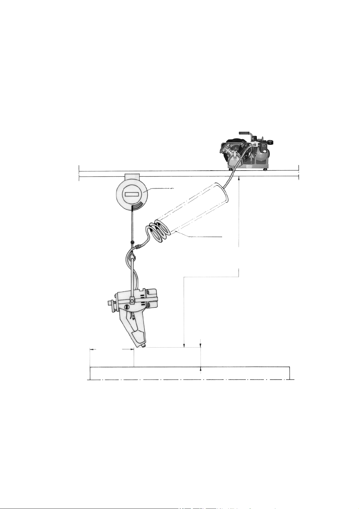
alternative
safety valve
maintenance unit
Place spring balancer
hoist over front third
slaughter bay.
spiral hose
compressor
The electrical connection
to the receptacle and main
switch must be made in
accordance with local regulations.
2000 mm
Schmid & Wezel
D 75433 Maulbronn
front third
top edge of slaughter bay
200 mm
Page / Seite
20 / 21
Version / Ausführung
11.2011

B. Declaration of conformity
EG-KONFORMITÄTSERKLÄRUNG
EC DECLARATION OF CONFORMITY
Hiermit erklären wir, dass die nachfolgend bezeichneten vollständigen Maschinen aufgrund ihrer Konzipierung und Bauart der
EG-Maschinenrichtlinie 98/37/EG und den grundlegenden Sicherheits- und Gesundheitsanforderungen entsprechen.
Bei einer nicht mit uns abgestimmten Änderung der Maschine verliert diese Erklärung ihre Gültigkeit.
We hereby declare that the following designated complete machines comply with the EC machine directive 98/37/EC and meet
the essential demands on health and safety on account of their conception and design.
The validity of this declaration expires when a modification to the machine is made without being coordinated with us.
CE
Bezeichnung der Maschine: Viehbetäubungsgerät
Typ EFA VB 115,VB 125, VB 130, VB 215, VB 225, VB 230, VB 235,VB512
Antrieb Pneumatikantrieb
Angewandte Vorschriften/Richtlinien: 98/37/EG
Angewandte A- Normen: DIN EN 1050
Angewandte B- Normen: DIN EN 294, DIN EN 954-1, DIN EN 954-2(Entwurf)
Angewandte C- Normen: --------Angewandte nationale Normen: ---------
Machine identification: Livestock stunning device
Type EFA VB 115,VB 125, VB 130, VB 215, VB 225, VB 230, VB 235,VB512
Actuation Pneumatic drive
Applied regulations/directives: 98/37/CE
Applied A- standards: DIN EN 1050
Applied B- standards: DIN EN 294, DIN EN 954-1, DIN EN 954-2(draft)
Applied C- standards: --------Applied national standards: ---------
Hersteller Name - Anschrift: Schmid & Wezel GmbH & Co
Manufacturer Name - Address: Maybachstrasse 2 , 75433 Maulbronn
Unterschrift: Signature: __________________________________________
Firma: Firma: Ulrich Merkle Dr. Norbert Lay
Angaben zum Unterzeichner: Geschäftsführer Leiter Technik und Entwickelung
Details of the undersigned: Managing director Head of engineering and development
Schmid & Wezel
D 75433 Maulbronn
Page / Seite
21 / 21
21
Version / Ausführung
11.2011
 Loading...