

Page 1
Betriebsanleitung/ Operating instructions
Wartungsanleitung/ Maintenance instructions
Ersatzteilliste/ Sparepart list
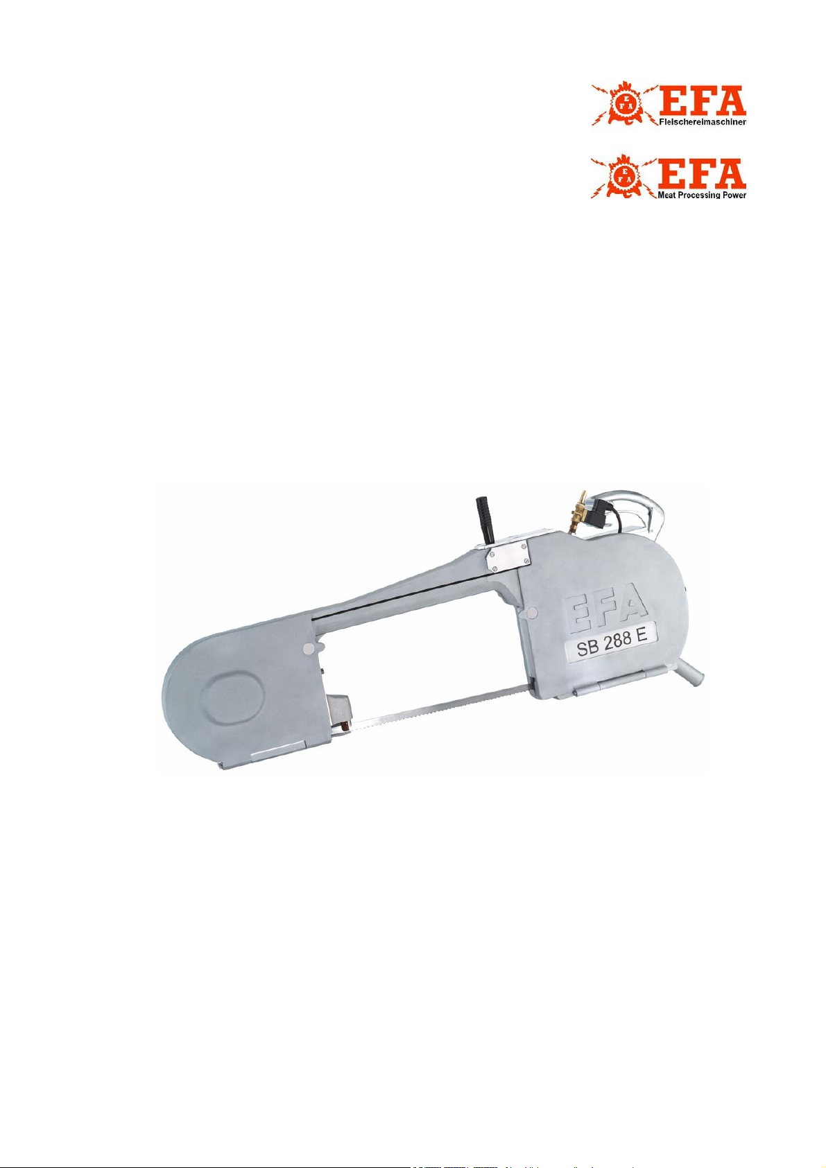
EFA SB 288 E
Halbierungssäge
Splitting Saw
Wichtige Informationen:
Diese Anleitung unbedingt dem Bedienpersonal aushändigen!
Important Informations:
Please forward these operating instructions to your operating
personell!
Schmid & Wezel
D 75433 Maulbronn
Ausführung/ Execution
03.2008
Page 2

INHALTSVERZEICHNIS
1. Verwendung, Lieferumfang, Zubehör....................................................................................2
1.1 Symbole in dieser Anleitung .........................................................................................................2
1.2 Bestimmungsgemäße Verwendung ...............................................................................................2
1.3 Lieferumfang ..............................................................................................................................2
1.4 Zubehör .....................................................................................................................................2
2. Sicherheitshinweise..............................................................................................................2
2.1 Allgemeine Sicherheitshinweise ....................................................................................................2
2.2 Verhalten am Arbeitsplatz ............................................................................................................3
3. Inbetriebnahme und Betriebssicherheit ................................................................................3
3.1 Erstinbetriebnahme .....................................................................................................................3
3.2 Schalterbetätigung ......................................................................................................................4
3.3 Arbeiten mit der Halbierungssäge .................................................................................................5
4. Montage........................................................................ .........................................................5
4.1 Sägebandwechsel........................................................................................................................5
4.2 Sägeband-Führung......................................................................................................................6
4.3 Einstellung des Federzuges ..........................................................................................................8
5. Instandhaltung................................ ......................................................................................8
6. Reinigung und Wartung.......................................................................................................11
6.1 Tägliche Reinigung nach Beendigung der Schlachtung .................................................................11
6.2 Tägliche Wartung der Halbierungssäge .......................................................................................12
6.3 Erweiterte Wartung
(nach ca. 50 Betriebsstunden) ..........................................................................................................12
6.4 Reparatur durch den Kundendienst.............................................................................................12
7. Transport und Lagerung ......................................................................................................12
8. Rücknahme von Altgeräten .................... .............................................................................12
A. Anhang / Appendix..... .........................................................................................................13
A.1 Technische Daten / Technical Data.............................................................................................13
A.2 Maschinen-Komponenten / Machine Components ........................................................................14
A.3 Schaltpläne / Circuit Diagrams ...................................................................................................15
A.4 Zubehörliste EFA SB 288 E / List of accesories EFA SB 288 E........................................................17
A.5 Ersatzteiliste EFA 288 E / Sparepart list EFA 288 E ......................................................................18
B. Konformitätserklärung...................................................................... ............... ....... ....... .....27
Schmid & Wezel
D 75433 Maulbronn
Seite/ Page
1
Ausführung/ Execution
03.2008
Page 3
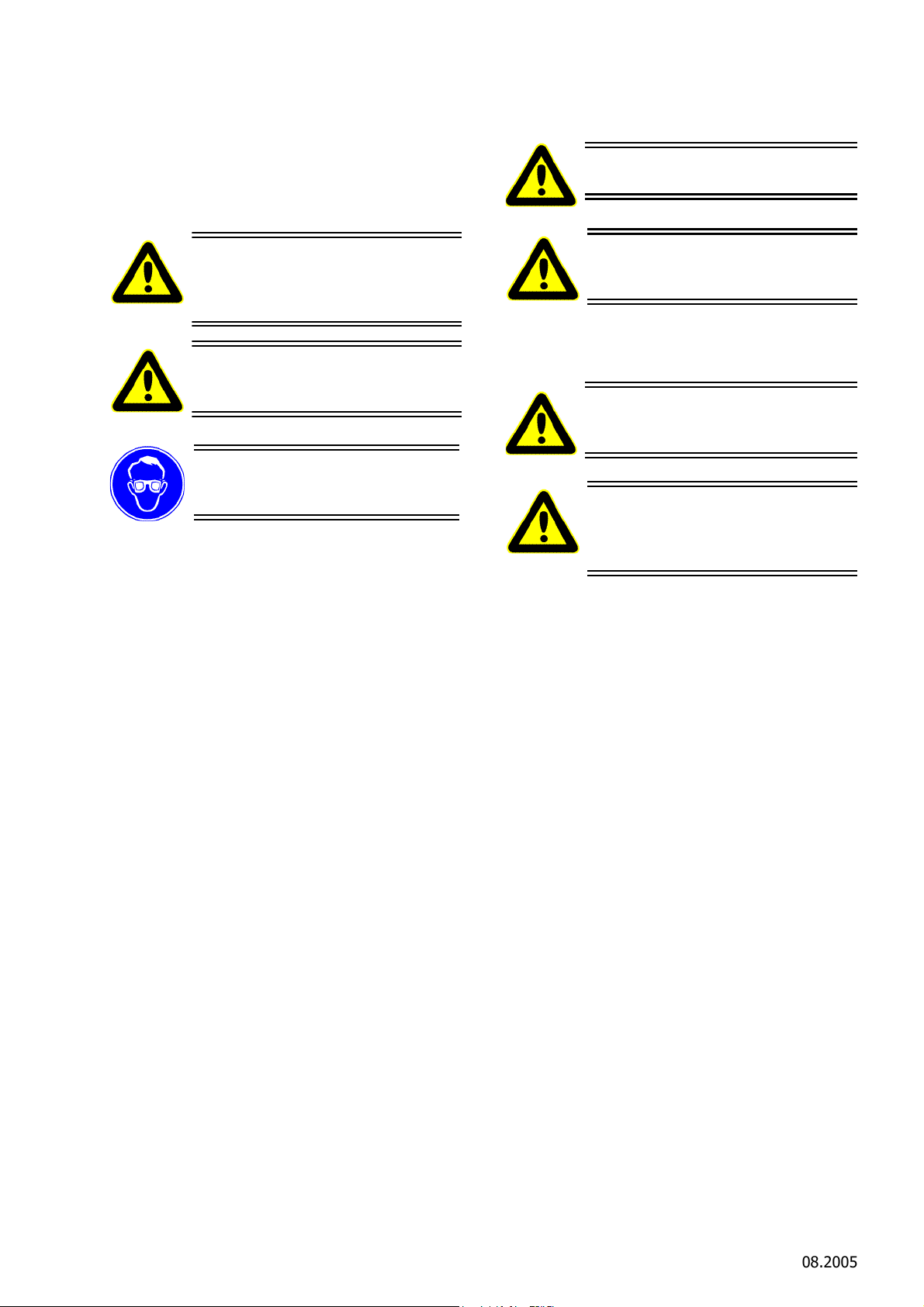
1. Verwendung, Lieferumfang,
Greifen Sie niemals in den Bereich
des laufenden Sägbandes. Sie
könnten sich sonst Gliedmaßen abtrennen!
Tragen Sie beim Arbeiten einen
Augenschutz bzw. eine Schutzbrille!
Hier ist äußerste Vorsicht und Umsicht
geboten. Bei Fehlverhalten besteht direkte Verletzungsgefahr für das Bedienpersonal oder Dritte. Außerdem kann die
Maschine Schaden nehmen.
Mit diesem Symbol versehene Textpassagen geben Ihnen wichtige Informationen und nützliche Tipps.
Zubehör
Hinweise, unbedingt lesen!
Diese Anleitung richtet sich an den Maschinenbediener. Bewahren Sie sie gut auf!
Die Bandsäge darf nur betrieben werden:
in technisch einwandfreiem Zustand bestim-
mungsgemäß sowie sicherheits- und gefahrenbewusst.
mit allen angebauten Sicherheitseinrichtungen.
gemäß den Sicherheitshinweisen.
nachdem das Bedienpersonal diese Anleitung,
insbesondere Kapitel 2 "Sicherheitshinweise" (S.
2) und Kapitel 3 "Inbetriebnahme und Betriebssicherheit" (S. 3) gelesen und verstanden hat.
Nur so können Fehlbedienungen vermieden und Gefahrensituationen richtig eingeschätzt werden.
Sauen in Mittel- und Großbetrieben, auch für
Rinder geeignet.
Die Maschine ist für eine andere Nutzung nicht ausgerüstet. Sollte eine anderweitige Nutzung vom Bediener gewünscht sein, bitte unbedingt vorher
Rücksprache mit der Firma Schmid & Wezel GmbH
& Co. (S&W) halten.
Bei allen anderen Anwendungen muss auf Unfallgefahr bzw. erhöhten Verschleiß hingewiesen werden.
Bei Zuwiderhandlung haftet allein der Benutzer.
1.2.2 Restgefahren
Da die Halbierungssäge für den industriellen Einsatz
an Tierkörpern vorgesehen ist, besteht die Möglichkeit sich zu verletzen bzw. bei grobem Missbrauch
jemanden zu töten. Somit ist bei missbräuchlichem
Umgang mit der Möglichkeit des direkten Todes
bzw. des Todes durch Verbluten zu rechnen. Deswegen muss immer auf den richtigen Umgang mit
der Maschine geachtet werden.
1.3 Lieferumfang
Bandsäge
1.1 Symbole in dieser Anleitung
Gefahrensymbol:
Informationssymbol:
1.2 Bestimmungsgemäße
Verwendung
1.2.1 Einsatzgebiete EFA SB 288 E
Hochleistungsbandsäge für Schweine und
Betriebsanleitung
1.4 Zubehör
Die Bestellnummern sowohl für im Lieferumfang
enthaltene Teile wie für Zubehör finden Sie in Anhang A.4 (S. 17) und Anhang A.5 (S. 18).
2. Sicherheitshinweise
2.1 Allgemeine Sicherheitshinweise
Befolgen Sie beim Gebrauch der Bansägen
unbedingt nachfolgende Sicherheitsmaßnahmen.
Der Sägebandwechsel sowie Installations-,
Wartungs- und Reparaturarbeiten dürfen nur,
bei den vom Stromnetz getrennten Geräten,
durchgeführt werden!
Wählen Sie ihre persönliche Schutzausrüstung
entsprechend ihrer betrieblichen Vorgaben.
Für die Bedienung wird vorausgesetzt, dass das
Bedienpersonal ausreichende Kenntnisse zum
Arbeiten mit dem Bandsägen hat.
Einweisung durch unser Fachpersonal.
Installations-, Wartungs-, und Reparaturarbei-
ten dürfen nur von autorisiertem Fachpersonal
durchgeführt werden.
Schmid & Wezel
D 75433 Maulbronn
Seite/ Page
2/ 27
Ausführung/ Execution
08.2005
Page 4
Bandsägen von Schmid & Wezel entsprechen
Die Halbierungssäge nur ausgeschaltet an das Betriebsnetz
anschließen!
Wesentliche Informationen, z. B. technische Datenblätter, Zeichnungen und
Stücklisten finden Sie in Anhang A (S.
13).
den einschlägigen Sicherheitsbestimmungen.
Die Maschine EFA SB 288 E ist aus Sicherheits-
gründen mit 2 Handgriffen zu bedienen.
2.2 Verhalten am Arbeitsplatz
1,5 qm groß sein. In diesen Bereich sollte kein anderer Arbeitsplatz hineinragen, da sonst auf Grund
der Bewegungen mit der Rippensäge Verletzungsgefahren entstehen könnten.
Die Beleuchtung des Arbeitsplatzes muss min. 500
Lux entsprechen.
1. Halten Sie Ihren Arbeitsplatz in Ordnung.
Unordnung kann Unfälle zur Folge haben.
2. Berücksichtigen Sie Umgebungseinflüsse. Sor-
gen Sie für gute Beleuchtung (min. 500 Lux).
3. Halten Sie andere Personen von Ihrem Arbeits-
platz fern. Arbeiten Sie konzentriert und mit
Vernunft. Benutzen Sie die Bandsäge nicht,
wenn Sie unkonzentriert und/oder müde sind.
4. Bewahren Sie die Bandsäge sicher auf. Unbe-
nutzte Geräte an einem trockenen Ort aufbewahren.
5. Arbeitskleidung: Tragen Sie keine weite Klei-
dung oder Schmuck - diese können von beweglichen Teilen erfasst werden. Tragen Sie beim
Arbeiten festes Schuhwerk. Tragen Sie generell
ein Haarnetz!
6. Vermeiden Sie eine nicht normale Körperhal-
tung. Sorgen Sie für sicheren Stand und halten
Sie jederzeit das Gleichgewicht.
7. Verwenden Sie nur Original EFA-Sägebänder.
Befolgen Sie die unter Sägebandwechsel aufgeführten Vorschriften. Siehe auch Kapitel 4.1
"Sägebandwechsel" (S. 5).
8. Lassen Sie keine Werkzeugschlüssel stecken.
Überprüfen Sie vor dem Einschalten, ob alle
Schlüssel entfernt sind.
9. Pflegen Sie Ihre Werkzeuge mit Sorgfalt. Ver-
wenden Sie nur scharfe und unbeschädigte
Sägebänder, damit Sie besser und sicherer
arbeiten können.
10.Verwenden Sie nur EFA – Originalzubehör. Ein
Gebrauch anderer Einsatzwerkzeuge oder Zubehöre kann verletzungsgefährdend für Sie sein.
Bei Nicht-Verwendung von Original-Ersatzteilen
erlischt der Garantieanspruch.
11.Veränderungen und Umbauten an der Maschine
sind nicht zulässig und entbinden Schmid &
Wezel von jeglicher Gewährleistung und Haftung.
3.1 Erstinbetriebnahme
3.1.1 Federzug
Die Maschine muss immer in Kombination mit einer
Gewichtsentlastung (Federzug) betrieben werden.
Bringen Sie diese mit einer Schiebelaufkatze an einem höher gelegenen Element über dem Arbeitplatz
oder an der Decke an. Informationen zur Feinabstimmung des Federzuges finden Sie unter Kapitel
4.3 "Einstellung des Federzuges" (S. 8).
Die Halbierungssäge möglichst kopflastig aufhän-
gen. Die Senkrechte kann bei Bedarf nach justiert
werden.
Auf Grund des Gewichts von 50 kg kann es beim Befestigen oder Lösen der Gewichtsentlastung zu einer
Gefährdung durch Abrutschen oder Herunterfallen
der Maschine kommen. Achten Sie auch darauf,
dass sich die Maschine weder am Karabinerhaken
noch am Haken der Halbierungssäge verklemmt.
Seien Sie umsichtig!
Wenn die Halbierungssäge nicht benutzt wird, ist
diese so abzulegen, dass es nicht zu unbeabsichtigtem Kontakt mit dem Sägeband kommen kann,
denn dieses ist scharf.
3.1.2 Elektrischer Anschluss
Die Halbierungssäge wird mit elektrischer Energie
betrieben und muss entsprechend der gesetzlichen
Vorschriften und der Vorschriften der örtlichen Energieunternehmen durch einen anerkannten Elektrotechniker angeschlossen werden.
3. Inbetriebnahme und
Betriebssicherheit
Arbeitsplatz
Der Stellplatz für den Bediener sollte mindestens
Schmid & Wezel
D 75433 Maulbronn
bei einer Motorspannung 200-480V ist eine
Vor dem primärseitigem Anschluss des Sicher-
Seite/ Page
3/ 27
Absicherung der Säge betriebsseitig mit einem
FI-Schalter abzusichern .
heitstransformators (nur Motorspannung 42V)
Ausführung/ Execution
08.2005
Page 5
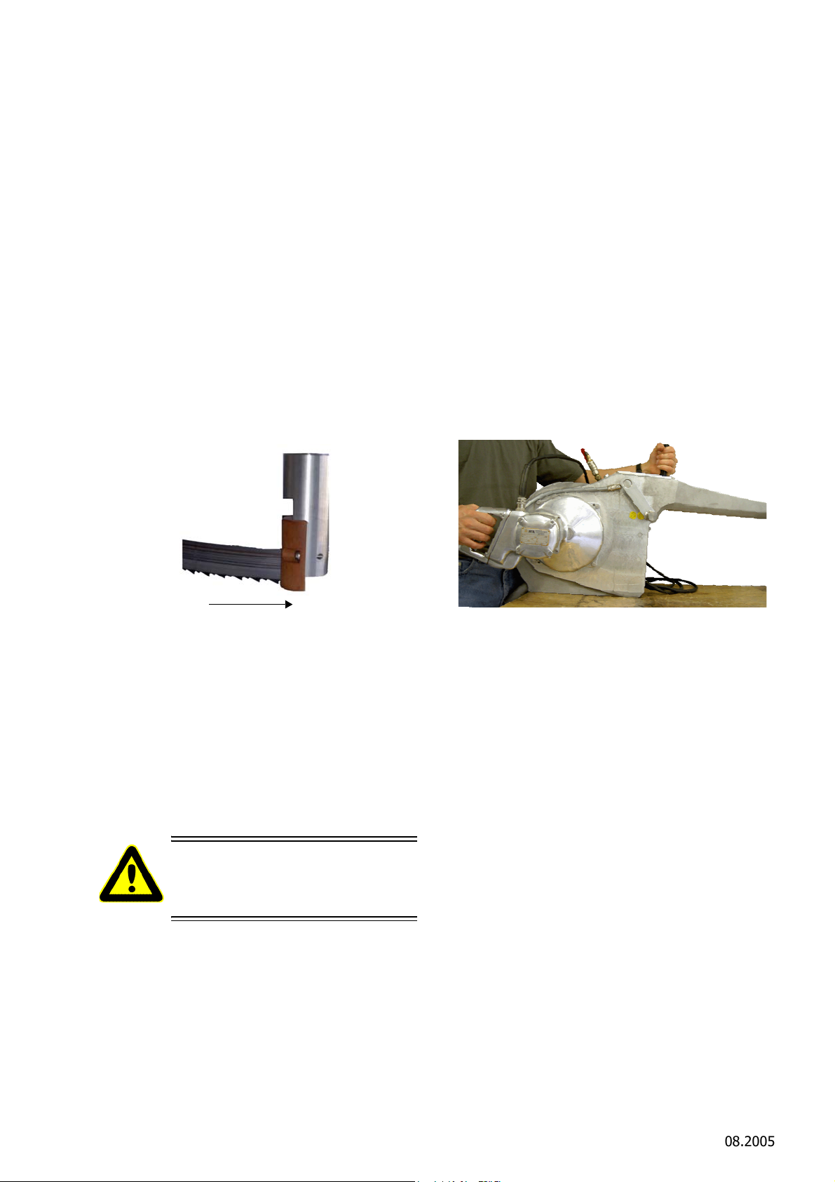
sind die Betriebsdaten von Stromnetz und der
Die Maschinen EFA SB 288 E ist mit einem Schaltergriff
und einem Führungsgriff gebaut. Siehe dazu
Abb. 2.
Abbildung 2: Einschalten
Schaltung des Transformators zu überprüfen.
Beim elektrischen Anschluss des Schaltschützes
(nur bei Motorspannung 42V) mit dem Sekundärausgang des Transformators sind die Kabelquerschnitte entsprechend Anhang A.3.4
"Leitungsquerschnitte/ Cross-sections of lines"
(S. 16) auszuführen.
Die Anschlusskabel der Maschinen sind entspre-
chend ihrer Kennzeichnung nach Schaltplan
anzuschließen.
Die Maschinen sind nach VDE und den Maschi-
nenrichtlinie 98/37/EG gebaut. Eigenmächtige
Veränderungen und Umbauten insbesondere
der Sicherheitsvorrichtungen ( Deckelsicherung)
an den Maschinen sind aus Gründen der
Betriebssicherheit nicht gestattet und entbinden
den Hersteller von Haftung und Gewährleistung.
Drehrichtung des Motors prüfen.
Sägeband richtig eingelegt ist.
Wasserversor
angeschlossen ist.
Aufhängung richtig und funktionsfähig montiert
ist.
Führungen federnd gelagert und nicht fest sind.
direkt vor Arbeitsbeginn scharfes Sägeband
montieren (siehe Kapitel 4.1.2 "Montage Sägeband" (S. 6)).
die allgemeinen Sicherheitshinweise berücksich-
tigt sind (siehe Kapitel 2 "Sicherheitshinweise"
(S. 2).
Zum Einschalten müssen beide Deckel (B) geschlossen sein (Einschaltsicherung).
gung eingeschaltet ist und richtig
3.1.3 Wasseranschluss
Bei der Maschine EFA SB 288 E wird die Wasserspülung über ein Magnetventil direkt mit der Motorschaltung gesteuert.Es ist nur ein
Kaltwasseranschluss vorhanden.
3.2 Schalterbetätigung
3.2.1 Einschalten
Vor dem Einschalten sind nachfolgende Punkte unbedingt zu überprüfen! Einen frühzeitigen Ausfall
des Sägebandes sowie Störungen des Schlachtablaufes können dadurch weitgehendst vermieden
werden.
Vor dem Einschalten prüfen, ob
Bandsäge funktionsfähig ist.
Abbildung 1: Laufrichtung
Erst bei korrekter Sägebandlage an
den Antriebs-/Umlankrad und in
den zwei Führungen darf die Säge
eingeschaltet werden!
Schmid & Wezel
D 75433 Maulbronn
Seite/ Page
4/ 27
Ausführung/ Execution
08.2005
Page 6
3.2.2 Ausschalten
Greifen Sie niemals in den Bereich
des laufenden Sägebandes. Sie
könnten sich sonst Gliedmaßen abtrennen !
Installationsarbeiten dürfen nur
von autorisiertem Fachpersonal
durchgeführt werden.
Tragen Sie beim Arbeiten einen
Augenschutz bzw. eine Schutzbrille!
Vor allen Montagearbeiten das Gerät vom Stromnetz trennen!
Montagearbeiten dürfen nur von
autorisiertem Fachpersonal durchgeführt werden.
Der Sägebandwechsel darf nur, bei
den vom Stromnetz getrennten Geräten, durchgeführt werden!
Greifen Sie niemals in den Bereich
des laufenden Sägebandes. Sie
könnten sich sonst Gliedmaßen abtrennen!
Schaltergriff loslassen, Maschine schaltet selbst-
tätig aus.
3.3 Arbeiten mit Halbierungssäge
3.3.1 Arbeitsgang
Vor dem Einsatz sind die Betriebsdaten von Stromnetz und Gerät auf Übereinstimmung zu prüfen.
Halbierungssäge an beiden Griffen sicher halten
und einschalten.
im laufenden Zustand in Fleischstück führen.
im laufenden Zustand aus Fleischstück nehmen
und dann am Schalterhebel abschalten.
Siehe auch Kapitel 3.2 "Schalterbetätigung" (S. 4).
3.3.2 Betriebssicherheit
Die Maschine EFA SB 288 E ist aus Sicherheitsgründen mit zwei Handgriffen zu bedienen.
Maschine an beiden Schaltergriffen sicher hal-
ten, niemals einhändig arbeiten.
im eingeschalteten Zustand besonders umsich-
tig handeln.
die Schutzvorrichtungen an der Säge dürfen
zum Zerlegen nicht entfernt werden.
4. Montage
4.1 Sägebandwechsel
Die Halbierungssägen haben eine Einschaltsicherung, d.h. wenn einer der beiden Deckel geöffnet
ist, kann die Maschine nicht eingeschaltet werden.
4.1.1 Demontage Sägeband
Beide Deckel (B) mit Lasche (C) öffnen (Deckel haben Magnetverschluss). Sägeband lösen, indem der
Drehmomentschlüssel (D) entgegen den Uhrzeigersinn gedreht wird. Das Sägeband ist nun entspannt.
Führung mit Hebel (E) hochheben und Sägeband
aus den Führungen schieben und über die Räder
herausnehmen (siehe Kapitel 4.2 "Sägeband-Führung" (S. 6).
SB 288 E = Drehmomentschlüssel lose beiliegend
(Artikelnummer 001 963 363)
zur sichereren Handhabung (Führung) sollte die
Säge an einem Federzug aufgehangen werden.
Im eingeschalteten Zustand nie in den Bereich
des Sägebandes greifen.
Während dem Einlegen des Sägebandes Motor-
schalter nicht betätigen.
Regelmäßig Aufhängung auf Schäden kontrollie-
ren.
allgemeine Sicherungsvorschriften, siehe Kapitel
2 "Sicherheitshinweise" (S. 2) beachten.
Schmid & Wezel
D 75433 Maulbronn
Seite/ Page
5/ 27
Ausführung/ Execution
08.2005
Page 7

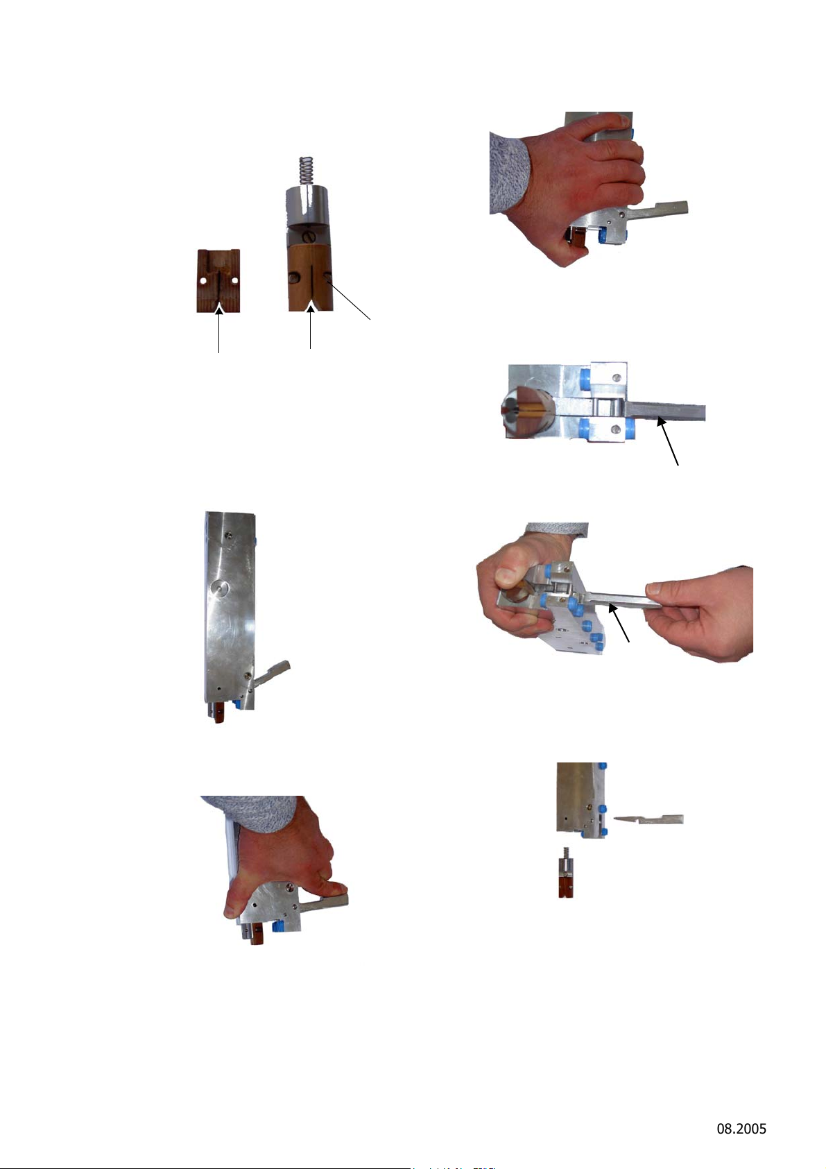
Abbildung 4: Sägebandwechsel
Richtung Bandlauf
Hebel E (Bild 64)
oben = Arbeitsposition
unten= Führung entspannt zum Wechseln
Sägeband
Einlaufspuren an Hartmetall
Spalt werkseitig 0,6 mm
bei Einlaufspuren Stäbe (b)
drehen
Freidrehung
2 Hartmetallrundstäbe
Umlenkung und Führung des Sägebandes
Druckfeder
Gefederte Abstützung des Sägedruckes
Fiberführung ( 003 009 634) im Bild nicht
gezeigt
4.1.2 Montage Sägeband
Sägeband bündig über die Räder mit den Zäh-
nen gegen das Gehäuse auflegen, die Zähne
müssen in Motorrichtung stehen. Die Schränkung der Zähne muss über dem ausgesparten
Durchmesser (Freidrehung, siehe Abb.6) der
Räder liegen.
Sägeband mittels Drehmomentschlüssel (D),
leicht vorspannen.
Führung mit Hebel (E) hochschieben, Sägeband
von Hand aufrichten und in Führungen einführen.
Hebel (E) loslassen (automatisch Arbeitsposi-
tion).
Sägeband mittels Drehmomentschlüssel (D)
spannen, bis Drehmomentschlüssel einrastet
(leichtes Klickgeräusch).
Maschine kurz laufen lassen, Sägeband zieht
sich selbstständig auf richtige Position der Laufräder.
Danach Sägeband nachspannen.
Die Zahnspitzen des Sägebandes sind gehärtet
und daher nicht nachschärfbar.
Abbildung 5: Sägebandführung
Hartmetallplatte (a) kann nach Verschleiß (Rie-
fenbildung), gewendet werden (vierseitig verwendbar). Ein rechtzeitiges Wenden verhindert
Rißbildung am Sägebandrücken.
Die Hartmetallrundstäbe (b) sind nicht einstell-
bar. Diese können durch verdrehen am gesamten Umfang unten und oben verwendet werden.
Bei Verschleiß neuer Einbau, dieser verhindert
Rißbildung und garantiert korrektes Sägen.
Die Sägebandführung muss beweglich sein.
Die Fiberführung (003 009 634) (siehe Abb.7)
muss regelmäßig auf Verschleiß geprüft werden
und ist ggf. zu ersetzen.
Der Abstand von Stirnseite Antriebs- und
Umlenkrades zum Sägeband muß 1,5 bis 2,5
mm betragen um den Freilauf der geschränkten
Zähne zu gewähren (siehe Abb.6).
Die Deckel (B) öffnen, siehe Kapitel 4.1.1
"Demontage Sägeband" (S. 5).
Sägeband spannen, siehe Kapitel 4.1.2 "Mon-
tage Sägeband" (S. 6).
4.2 Sägeband-Führung
Die Bandsägen haben zwei gleiche Sägeband-Führungen, diese sind ein wichtiger Teil der Bandsäge
und müssen täglich gereinigt, überprüft und bei Verschleiß rechtzeitig gewechselt werden.
Die Führungen des Sägebandes beinhalten
folgende Funktionen (siehe Abb.5):
Hartmetallplatte
Abstützung des Sägedruckes
Schmid & Wezel
D 75433 Maulbronn
Seite/ Page
6/ 27
Abbildung 6: Abstand Antriebs-/Umlenkrad zum
Sägeband
Ausführung/ Execution
08.2005
Page 8
Führungswechsel
Spalt max. 2,0 mm Neu 0,6 mm
Fiberführung
Hebel (64)
Hebel (64)
Ist der Spalt größer als 2,0 mm muss die Fiberführung gewechselt werden (siehe Abb.7).
Abbildung 7: Führungswechsel
Demontage Führung aus Leiste
Im Folgenden sind die Schritte zur Demontage der
Führung aufgeführt:
Führung komplett
2. Führung oben halten.
Abbildung 10: Führung oben halten
3. Hebel (Bild-Nr. 64) aus Halterung nehmen.
Abbildung 11: Hebel (64)
Abbildung 8: Führung
1. Führung nach oben drücken.
Abbildung 9: Führung nach oben drücken
Abbildung 12: aus der Halterung nehmen
4. Führung und Hebel können jetzt demontiert werden.
Abbildung 13: Demontage Führung und Hebel
Schmid & Wezel
D 75433 Maulbronn
Seite/ Page
7/ 27
Ausführung/ Execution
08.2005
Page 9

4.3 Einstellung des Federzuges
Die Feinabstimmung des Federzuges erfolgt über
die PLUS/MINUS-Schraube an seinem Gehäuse (siehe Abb.14).
Abbildung 14: Federzug
drehen Sie dazu die Schraube in Richtung
MINUS bis sich das Gerät frei schwebend im
Gleichgewicht (mit der Zugfeder) auf Arbeitshöhe befindet
Sollte kein Auszug möglich sein, ist der Federzug
blockiert und eine Neueinstellung ist notwendig:
drehen Sie die Schraube in Richtung PLUS bis
ein Auszug möglich wird und beginnen Sie
erneut mit der Feineinstellung (siehe oben).
5. Instandhaltung
Während des Betriebes kann die Funktion gestört
sein, die Fehlerbehebung ist in den meisten Fällen
aber relativ einfach. In Tabelle 1: „Störungen und
ihre Behebungen“ sind diese Störungen mit möglichen Ursachen und resultierenden Behebungsmöglichkeiten aufgeführt.
Schmid & Wezel
D 75433 Maulbronn
Seite/ Page
8/ 27
Ausführung/ Execution
08.2005
Page 10

Tabelle 1: Störungen und ihre Behebung
Störung mögliche Ursache Behebung
1. Säge läuft beim Betätigender
Schalter nicht an
(Fehlersuche an der Säge)
3. Säge läuft beim Betätigen der
Schalter an, keine Leistung
Anschlussleitung Kabelbruch Anschlussleitung prüfen
bei 42V-Ausführung Anschluss an
Schaltschütz prüfen
Mikroschalter (6) defekt Prüfen auf elektr. Funktion; ggf.
austauschen
Deckel vorne/ hinten nicht fest
verschlossen oder liegen nicht
fest an
Anschlussleitung nicht fest verklemmt
Motorwickelung defekt Motor demontieren und prüfen,
Elektrischer Durchgang Mikroschalter (6) von vorderem Handgriff auf Klemme prüfen
Leitungsquerschnitt oder Länge
zu klein dimensioniert
Prüfen und ggf. Deckel fest
schließen bis Kontakt vorhanden
Klemmen prüfen und nachziehen/
neu verbinden
ggf. austauschen
Kabel oder Mikroschalter austauschen bzw. neu verbinden
Abmaße nach Anhang A.3.5 "Leitungsquerschnitte/ Cross-sections
of lines" (S. 18) prüfen und ggf.
ändern
Spannungsabfall im Hauptnetz Spannungsabfall prüfen und
Bandspannung nicht ausreichend Drehmomentschlüssel nachzie-
4. Säge läuft beim Betätigender
Schalter nicht immer an oder
zeitversetzt an/aus
5. Hoher Bandverschleiß Führungsplatte vorderes Leitrol-
Verkabelung an den Klemmstellen locker
lenrad sitzt zu fest oder ist verklemmt
Drehmoment falsch eingestellt Mit Drehmomentschlüssel muss
beseitigen (hierzu können ggf.
Prüfgeräte von Fa. S&W geliefert
werden)
hen
Klemmen prüfen und Fehler
beseitigen
Prüfen auf Leichtgängigkeit, ggf.
mit Drehmomentschlüssel entspannen oder neu fetten
geprüft werden (Drehmoment zu
hoch)
Schmid & Wezel
D 75433 Maulbronn
Seite/ Page
9/ 27
Ausführung/ Execution
08.2005
Page 11

Tabelle 1: Störungen und ihre Behebung
6. Sägeschnitt verläuft Führung Sägeband verschlissen siehe Kapitel 4.2 "Sägeband-Füh-
rung" (S. 6)
Leiste (vorne oder hinten) Sitz für
Führung ausgeschlagen, dadurch
schräge Lagerung der Führung
Aufhängung Bandsäge ist Bolzen
eingelaufen, dadurch hängt die
gesamte Säge schief
Band liegt falsch auf, keine
Schränkung vorhanden
Leitrollenrad vorne oder hinten
eingelaufen
7. Band springt vom Rad ab Leitrollenrad vorne oder hinten
eingelaufen oder verschlissen
Drehmoment zu gering eingestellt Mit Drehmomentschlüssel Band
Kugellager der Räder (vorne /hinten) ausgeschlagen
Rahmen verzogen Totalschaden; neuer Rahmen mit
Leiste austauschen, Leiste immer
paarweise (vorne und hinten)
austauschen!!
Aufhängung korrigieren oder Bolzen austauschen
Band mit Zähnen zum Motor auf
Rad legen siehe Kapitel 4.2
"Sägeband-Führung" (S. 6)
Räder prüfen ggf. austauschen
Räder prüfen ggf. austauschen
nachspannen
Lagerspiel prüfen und Lager ggf
austauschen
Montage Einzelteile
8. Während der Reinigung läuft
kein Wasser (Säge)
9. Während der Reinigung läuft
kein Wasser (Betrieb)
Anschluss an Magnetventil lose Prüfen ggf Schläuche austau-
schen
Magnetventil defekt Prüfen und ggf austauschenn
Düsen oder Wasserrohr verkalkt
oder verschmutzt
Wasseranschluss defekt oder lose Prüfen ggf Schläuche austau-
Wasseranschluss betriebsintern
nicht vorhanden oder defekt
Teile säubern oder austauschen
schen
Prüfen und korrigieren
Schmid & Wezel
D 75433 Maulbronn
Seite/ Page
10/ 27
Ausführung/ Execution
08.2005
Page 12
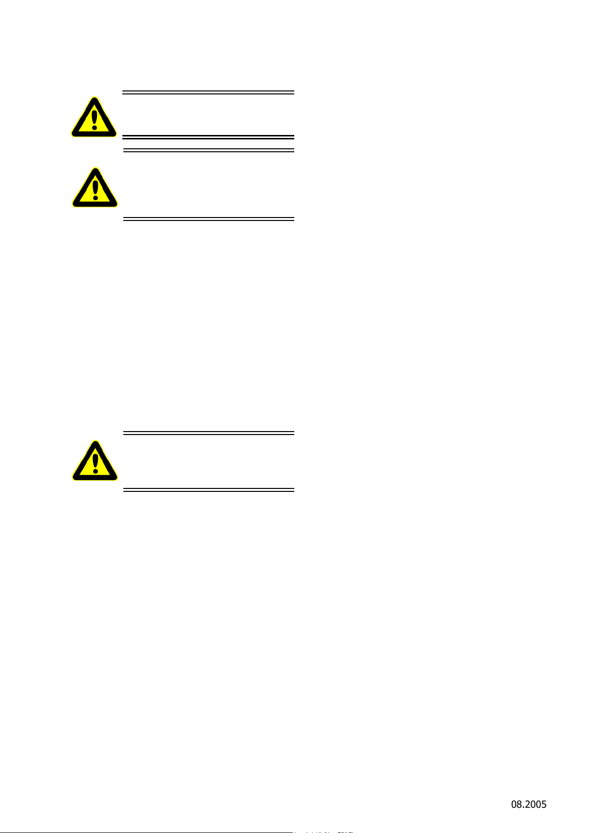
6. Reinigung und Wartung
Vor allen Reinigungs- und Wartungsarbeiten das Gerät vom Betriebsnetz trennen.
Vor allen Wartungsarbeiten müssen die Deckel (B) geöffnet sein
(Einschaltsicherung), dadurch ist
ein unbeabsichtigtes Einschalten
nicht möglich!
Keine scharfen Lösungsmittel zusetzen! Keinen Dampf- bzw. Hochdruckstrahler verwenden! Gerät
nicht in Wasser tauchen!
6.1 Tägliche Reinigung nach
Beendigung der Schlachtung
Ein störungsfreier Dauerbetrieb ist nur dann gewährleistet, wenn die Halbierungssäge ständig hygienisch einwandfrei sauber gehalten wird.
Üblicherweise sollte das Gerät vor jeder Reinigung
desinfiziert werden.
Beachten Sie dazu die geltenden Sicherheits- und
Hygieneanforderungen (DIN EN 1672)!
Desinfektionsmittel dürfen weder direkt noch indirekt mit Lebensmitteln in Berührung kommen. Spülen Sie das Gerät daher nach der Desinfektion mit
klarem Wasser ab.
die zu reinigende Fläche verteilen und 15 - 20 min.
einwirken lassen. Anschließend gelösten Schmutz
mit warmen Wasser manuell abwaschen.
Empfohlene Reinigungsmittel
Diversey Lever Tego 2000:
Oberflächenaktives Desinfektionsmittel
Diversey Lever GmbH
Mallaufstr. 50-56, 68219 Mannheim
Alternativ:
P3-topax 91:
Oberflächenaktives Desinfektionsmittel
Henkel-Ecolab Deutschland GmbH
Postfach 13 04 06, 40554 Düsseldorfein
Reinigungsplan und weitere Einzelheiten erhalten
Sie unter o. g. Firmenadressen
Die o.g. Reinigungsmittel sind nur eine Empfehlung;
bei der Verwendung von anderen Reinigungsmittel
muss die Materialverträglichkeit und Hygienevorschriften kundenseitig geprüft werden.
6.1.3 Schmiermittel
Das Schmiermittel unterliegen den im Lebensmittelbereich notwendigen Vorschriften (DIN 1672).
Empfohlenes Schmierfett Getriebe
Klübersynth UH1 12-1600 (H1)
EFA-Spezialfett
Best.-Nr. 001 365 644 (0,8 kg)
Best.-Nr. 001 365 645 (5,0 kg)
Fettmenge für das Getriebe:
EFA SB 288 E: 600 g
6.1.1 Desinfektion
Das Bandsäge wird nicht während des Betriebes
nach jedem Schnitt automatisch mit heißem Wasser
(82 °C) desinfizieren. Sollte eine Desinfizierung notwendig sein, muss eine gesonderte Sterilisationskabine benutzt werden (Bestell-Nr.: 007 009 329)
6.1.2 Reinigung der Halbierungssäge
Nach dem Arbeitseinsatz das Sägeband entspannen
(siehe Kapitel 4.1.1 "Demontage Sägeband" (S. 5)),
das Sägeband abnehmen und mit heißem Wasser
reinigen und trocknen.
Ebenso die Führung nach jedem Einsatz herausnehmen und die Einsatzbohrung komplett reinigen (siehe Kapitel 4.2 "Sägeband-Führung" (S. 6).
Zur Reinigung das Gerät mit Lappen, Bürste und
warmen Wasser (40 - 55°C) reinigen. Hartnäckige
oder verkrustete Verschmutzungen müssen eingeweicht werden. Reinigen Sie dazu mit einem Reinigungsmittel, wenn möglich als Schaum, das Sie auf
Schmid & Wezel
D 75433 Maulbronn
Empfohlenes Schmierfett für alle Schmierstellen, Führung und Drehmomentschlüssel
Molykote Lomgterm W2
EFA-Spezialfett
Best.-Nr. 001 365 623 (1 kg)
Best.-Nr. 001 365 624 (5 kg)
Empfohlenes Öl für Ölbad Drehmomentschlüssel
Weissöl Shell-Ondina G17, 15 Centistok / 40°
Spezialöl
Best.-Nr. 001 365 611 (0,5 l)
Best.-Nr. 001 365 612 (5,0 l)
Seite/ Page
11/ 27
Ausführung/ Execution
08.2005
Page 13

6.2 Tägliche Wartung der
Vor allen Reparaturarbeiten das
Gerät vom Betriebsnetz trennen.
6.4 Reparatur durch den
Halbierungssäge
Um den hygienischen Anforderungen zu genügen,
muss die Bandsäge nach jedem Einsatz gewartet
werden.
6.2.1 Schmierung
Nach jeder Reinigung das Sägeband mit säurefreiem EFA-Spezialöl leicht einölen, die Führung mit
EFA-Schmierfett einfetten.
6.2.2 Führung
Die Führung besonders sorgfältig warten. Bei Verschleiß rechtzeitig nachstellen bzw. unverzüglich
austauchen.
Die Führung auf Gängigkeit durch die Feder überprüfen und fetten.
6.2.3 Sägeband
Regelmäßig das Sägeband überprüfen, bei Verschleiß austauschen.
6.2.4 Motor
Die Kondenswasserbohrungen an der Unterseite
des Motors mit einem stumpfen, nichtmetallischen
Gegenstand freihalten. Größere Ansammlungen von
Kondenswasser führen zu Motorausfall (Korrosion
der Wicklung) und hohen Reparaturkosten.
Kundendienst
Reparaturen dürfen nur von autorisierten
Fachkräften vorgenommen werden.
Für Reparaturen steht Ihnen unsere Serviceab-
teilung zur Verfügung. Bitte wenden Sie sich im
Falle einer Reparatur an die nächstgelegene
Vertragswerkstatt oder direkt an unser Stammhaus.
Bitte beachten Sie, dass Elektrowerkzeuge
grundsätzlich nur durch Elektrofachkräfte repariert werden dürfen, da durch unsachgemäße
Reparaturen erheblich Gefährdungen für den
Benutzer entstehen können.
Auf Wunsch können für die Reparaturwerkstatt
mit Fachkräften Ersatzteillisten nachgereicht
werden.
Nach Reparaturen müssen die Getriebe jedes
Mal erneut dauergeschmiert werden!
7. Transport und Lagerung
6.3 Erweiterte Wartung
(nach ca. 50 Betriebsstunden)
6.3.1 Halbierungsäge
Kugellager der Leitrollenräder prüfen und gegebenenfalls nachfetten.
6.3.2 Führung
Beide Führungen leicht fetten.
6.3.3 Drehmomentschlüssel
Der Drehmomentschlüssel soll über das Wochenende in ein Ölbad gelegt werden, nicht nachschmieren.
6.3.4 Getriebe
Die Getriebe haben Dauerschmierung. Diese muss
nur bei Reparaturen erneuert werden.
Die Maschine muss in einem trockenen, gelüfteten
Raum gelagert werden.
Die Maschine ist nach Kapitel 6.1.2 "Reinigung der
Halbierungssäge" (S. 11) zu reinigen und in trockenem Zustand zu transportieren.
Es ist darauf zu achten, dass die Maschine beim
Transport nicht beschädigt wird.
8. Rücknahme von Altgeräten
Geben Sie Altgeräte zum Entsorgen an das Stammhaus zurück.
Schmid & Wezel
D 75433 Maulbronn
Seite/ Page
12/ 27
Ausführung/ Execution
08.2005
Page 14
Operating instructions / Betriebsanleitung
Maintenance instructions / Wartungsanleitung
Sparepart list / Ersatzteilliste
EFA SB 288 E
Splitting Saw
Halbierungssäge
Important Information:
Please forward these operating instructions to your operating
personell!
Wichtige Informationen:
Diese Anleitung unbedingt dem Bedienpersonal aushändigen!
Schmid & Wezel
D 75433 Maulbronn
Ausführung / Version
03.2008
Page 15

TABLE OF CONTENTS
1. Verwendung, Lieferumfang, Zubehör....................................................................................2
1.1 Symbole in dieser Anleitung .........................................................................................................2
1.2 Bestimmungsgemäße Verwendung ...............................................................................................2
1.3 Lieferumfang ..............................................................................................................................2
1.4 Zubehör .....................................................................................................................................2
2. Sicherheitshinweise..............................................................................................................2
2.1 Allgemeine Sicherheitshinweise ....................................................................................................2
2.2 Verhalten am Arbeitsplatz ............................................................................................................3
3. Inbetriebnahme und Betriebssicherheit ................................................................................3
3.1 Erstinbetriebnahme .....................................................................................................................3
3.2 Schalterbetätigung ......................................................................................................................4
3.3 Arbeiten mit der Halbierungssäge .................................................................................................5
4. Montage........................................................................ .........................................................5
4.1 Sägebandwechsel........................................................................................................................5
4.2 Sägeband-Führung......................................................................................................................6
4.3 Einstellung des Federzuges ..........................................................................................................8
5. Instandhaltung................................ ......................................................................................8
6. Reinigung und Wartung.......................................................................................................11
6.1 Tägliche Reinigung nach Beendigung der Schlachtung .................................................................11
6.2 Tägliche Wartung der Halbierungssäge .......................................................................................12
6.3 Erweiterte Wartung
(nach ca. 50 Betriebsstunden) ..........................................................................................................12
6.4 Reparatur durch den Kundendienst.............................................................................................12
7. Transport und Lagerung ......................................................................................................12
8. Rücknahme von Altgeräten .................... .............................................................................12
A. Anhang / Appendix..... .........................................................................................................13
A.1 Technische Daten / Technical Data.............................................................................................13
A.2 Maschinen-Komponenten / Machine Components ........................................................................14
A.3 Schaltpläne / Circuit Diagrams ...................................................................................................15
A.4 Zubehörliste EFA SB 288 E / List of accesories EFA SB 288 E........................................................17
A.5 Ersatzteiliste EFA 288 E / Sparepart list EFA 288 E ......................................................................18
B. Konformitätserklärung...................................................................... ............... ....... ....... .....27
Schmid & Wezel
D 75433 Maulbronn
Page / Seite
1
Version / Ausführung
03.2008
Page 16
1. Application, scope of delivery
Never reach into the operating
range of the saw band as limbs
could be severed!
Always wear goggles or other
effective eye protection!
Proceed with extreme caution. In the
event of incorrect operation, there is a
risk of injury to operating staff and other
persons. There is also a risk of damage
to the machine.
This symbol highlights sections in the
text containing important information
and useful hints.
1.1 Symbols used in this manual
and accessories
Important notes!
This manual has been specifically compiled for
machine operators. Keep it near the machine for
future reference!
The splitting saw may only be operated
for the intended purpose, with due care as
regards safety, and if the equipment is in proper
working order
if all safety devices are properly mounted
according to the safety instructions in this
manual
after instruction of the operating personnel, who
must also have read and understood the
instructions in chapter 2 "Safety instructions"
(page 3) and chapter 3 "Commissioning and
operational safety" (page 3).
This is necessary in order to prevent incorrect
operation and to enable operators to assess
potential risks accurately.
Danger:
Information:
1.2 Proper use
1.2.1 Applications of EFA SB 288 E
High-performance splitting saw for hogs and
saws in medium-sized and large processing
plants.
The machine is not designed for any other use. If
you wish to use the equipment for other purposes,
first consult Schmid & Wezel GmbH & Co (S&W).
If the machine is used for any other purposes,
please note that there is a greater risk of serious
injury and increased wear to machine parts. The
operator shall be solely liable for any damage arising
from improper use of the equipment.
1.2.2 Residual risks
As the splitting saw is designed for the cutting of
carcasses, there is a risk of serious injury to
persons. If handled improperly or without due care,
persons might even be killed instantly, or die as a
consequence of serious blood loss. It is therefore
imperative that the splitting saw is handled properly
and according to the instructions in this manual.
1.3 Scope of delivery
Splitting saw
Operating manual
1.4 Accessories
For order numbers of standard equipment and
accessories, please refer to Appendix A.4 (page 17)
and Appendix A.5 (page 18).
Schmid & Wezel
D75433 Maulbronn,
Page / Seite
2 / 27
Version / Ausführung
08.2005
Page 17
2. Safety instructions
When connecting the splitting saw
to the pressure supply line, ensure
that it is switched off.
For detailed information, technical data,
parts lists and drawings of the
equipment, see Appendix A (page 13).
2.1 General safety instructions
When operating the splitting saw, always
adhere to the following safety instructions:
Before replacing the saw bands, or carrying out
installation, maintenance or repair work,
disconnect the machine from the power supply
line.
Wear personal protective equipment that is
appropriate for your work.
Only personnel who have been properly trained
and instructed in the safe use of the splitting
saw may operate the machine.
9. Handle your tools with care. Use only sharp and
undamaged saw bands to ensure safe and
efficient working.
10.Use only original EFA accessories. If other tool
inserts or accessories are used, there is also an
increased risk of injury to the operator and
other persons. The use of spare parts other
than original Schmid & Wezel parts shall void all
warranty.
11.It is prohibited to modify the machine in any
way. Schmid & Wezel rejects any liability for
damages arising from modified equipment.
3. Commissioning and
operational safety
Instruction by our specialist technicians
Installation, maintenance and repair work may
only be carried out by suitably trained and
authorised specialist technicians.
Splitting saws by Schmid &Wezel conform to all
relevant safety standards
For safety reasons, the EFA SB 288 E is
equipped with 2 operating handles.
2.2 Workplace safety
1. Keep your workplace tidy.
2. Ensure that the workplace environment is
suitable for the use of the tool and properly
illuminated (min. 500 lx).
3. Prevent unauthorised persons from accessing
your workplace. Concentrate on your work and
use common sense. Do not handle the splitting
saw, if you feel tired and/or find it difficult to
concentrate.
4. Keep the splitting saw in a safe place. While not
in use, store it in a dry place.
5. Work clothing: Do not wear loose clothing or
jewellery, as such items could become
entangled in moving machine parts. Wear safety
footwear. Always wear a hairnet!
6. Avoid an unnatural posture. Make sure that you
stand firmly and do not lose your balance.
7. Use only original EFA saw bands. Always adhere
to the instructions for the replacement of saw
band. See also chapter 4.1 "Changing saw
band" (page 5).
8. Never leave spanners or wrenches attached to
the tool. Before starting the machine, inspect
the splitting saw to ensure that all spanners and
wrenches have been removed.
Workplace
The working area for the operator must be of a
size of at least 1.5 m². This area must be kept clear
and may not be shared with any other staff, as the
saw is moved during operation and could injure
other persons.
The working area must be illuminated with min.
500 lx.
3.1 Commissioning
3.1.1 Spring-loaded pulley
The machine may only operated in conjunction with
a spring-loaded pulley. The pulley must be attached
to a sliding crab secured to a beam above the
workplace or the ceiling. For detailed information on
how to install and balance the spring-loaded pulley,
please refer to chapter 4.3 "Adjusting spring-loaded
pulley" (page 8).
The splitting saw must be suspended in such a way
that its head section faces downwards. If required,
the tool can be realigned in vertical direction.
As the machine weighs about 50 kg, there is a risk
of injury if it is dropped while being attached or
removed from the pulley system. Ensure that the
splitting saw is not jammed at the hooks. Always
proceed with special care when attaching or
Schmid & Wezel
D75433 Maulbronn,
Page / Seite
3 / 27
Version / Ausführung
08.2005
Page 18
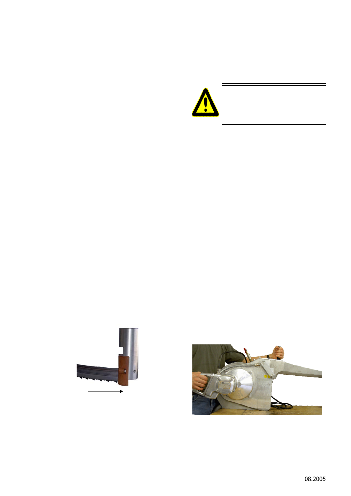
removing the saw from the pulley.
Figure 2: Switching ON
When the splitting saw is not used, it must be stored
in such a way that persons cannot inadvertently
come into contact with its band, as it is extremely
well honed.
3.1.2 Connection to electric power supply
The splitting saw is driven by an electric motor and
must be connected to the mains by an approved
electrician according to the applicable statutory
regulations and the instructions of the local energy
supply company.
At a motor voltage of 200-480V, the saw must
be protected with a residual current circuit
breaker (to be provided by operator).
Before connecting the safety transformer (only
for motor voltage 42V), check the operating
data of the power supply mains and the settings
of the transformer.
When connecting the contactor (only for motor
voltage 42V) to the secondary transformer
output, ensure that all cable cross-sections
conform to the specifications in Anhang A.3.4
"Leitungsquerschnitte/ Cross-sections of lines"
(S. 16).
The connecting cables of the machine must be
connected according to the circuit diagram.
The machine conforms to VDE standards and
the European Machinery Directive 98/37/EC. For
safety reasons, the unauthorised modification
and extension of the machine in general and its
safety devices (safety cover) in particular are
prohibited. The manufacturer shall not be liable
for damages caused by modified equipment.
Modifications to the machine void all warranty.
Check the motor's direction of rotation.
for cold water.
3.2 Operation of switch
Before switching on the saw,
3.2.1 Switching ON
Before switching on the saw, the following checks
must be carried out, as this helps prevent damage
to the saw band and interruption in the processing
workflow.
Before switching on the machine, check whether
the band saw is in proper working order
the saw band is properly inserted
the water supply has been switched on and is
connected correctly
the suspension mechanism is correctly mounted
and in proper working order
the guides are flexibly mounted and not rigid.
Mount a share saw band only immediately
before starting working with the tool (see
chapter 4.1.2 "Changing saw band" (page 6)).
All general safety instructions chapter 2 "Safety
instructions" (page 3) must be strictly adhered
to.
Before switching on the machine, ensure that both
covers (B) are closed (switch-on protection).
The EFA SB 288 E is equipped with a switching lever
and a fixed handle.
The EFA SB 288 E is equippped withe one switching
handel and one guide handle. See also Abb. 2.
ensure that the saw band is
properly positioned on the drive
and guide wheels and in the two
guides!
3.1.3 Connection to water supply
The water spraying system of the EFA SB 288 E is
controlled by means of a solenoid valve that is
connected directly to the motor switching system.
The machine is only equipped with one connection
Schmid & Wezel
D75433 Maulbronn,
Figure 1: Direction of movement of band
Page / Seite
4 / 27
Figure 2: Switching ONVersion / Ausführung
08.2005
Page 19
Fkggg
Figure 3: Switching on EFA 288E - option 2
See also chapter 3.2 "Operation of switch" (page 4).
3.3.2 Operational safety
For safety reasons, the EFA SB 288 E is equipped
with two operating handles.
Hold the machine by the fixed handle and the
switching lever. Never attempt to operate it with
one hand.
While the tool is switched on, proceed with
extreme caution.
Never remove any safety devices to disassemble
the splitting saw.
If the switching lever is released during operation
the splitting saw is switched off. Actuate the
switching lever again to restart the splitting saw.
The two switches must be operated
simultaneously (within 0.3 seconds of
each other).
3.2.2 Switching OFF
Release the switch handles. The machine is
automatically switched off.
3.3 Working with the splitting saw
Never reach into the operating
range of the saw band as limbs
could be severed!
All installation work must be
carried out by suitably trained and
authorised technicians.
For safe operation with proper guidance, the
splitting saw should be attached to a springloaded pulley system.
When switched on, do not reach into the
operating range of the saw band.
Do not actuate the motor switch while inserting
the saw band.
Regularly check the suspension mechanism for
damage.
Adhere to the general safety instructions in
chapter 2 "Safety instructions" (page 3).
4. Installation and assembly
Before carrying out any assembly
work, disconnect the saw from the
power supply!
All installation and assembly work
must be carried out by suitably
trained and authorised
technicians.
4.1 Changing saw band
Always wear goggles or other
effective eye protection!
3.3.1 Cutting process
Prior to starting the saw, compare the technical data
of the power mains with that of the tool.
Hold the splitting saw with both hands by the
handles and switch it on.
Insert into meat while the saw band is running.
Remove the saw from the cut while the band is
still running and release the switching lever to
switch off the saw.
Schmid & Wezel
D75433 Maulbronn,
Page / Seite
The saw band may only be changed
after the machine has been
disconnected from the power
supply!
Never reach into the operating
range of the saw band as limbs
could be severed!
The splitting saw is equipped with a switch-on
protection mechanism, so that it cannot be started
if one of the two covers is opened.
Version / Ausführung
5 / 27
08.2005
Page 20
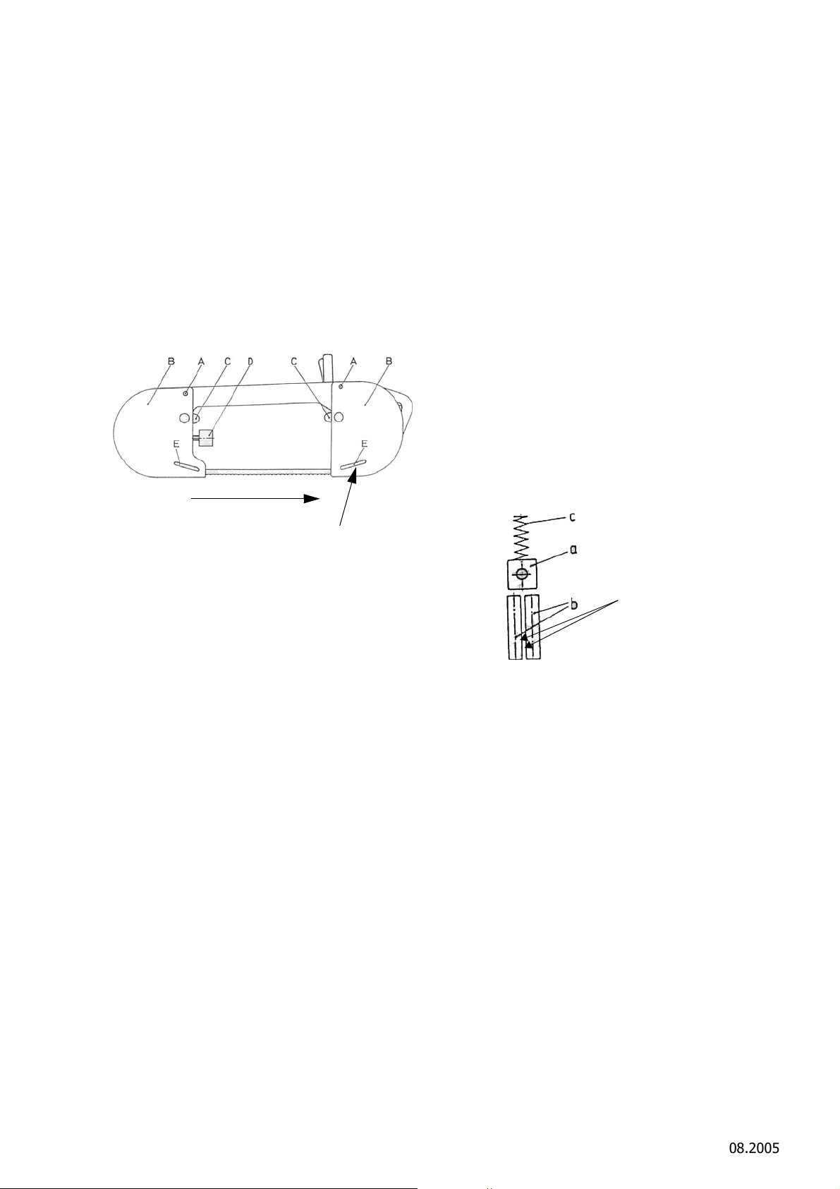
4.1.1 Dismantling saw band
Direction of band run
Lever E (fig. 64)
top = working position
bottom = guide
mechanism released for
band change
Saw band
Grooves in hard metal
Gap (default width 0.6 mm)
Turn rods (b) if there are
grooves
Open the two covers (B) by pulling the tab (C) (the
covers are equipped with magnet snap
mechanisms). Release the saw band by turning the
torque wrench (D) anticlockwise. The saw band is
now released.
Lift the guide mechanism with the lever (E) and slide
the band from the guides and across the wheels
(see chapter 4.2 "Saw band guides" (page 6).
SB 288 E = Torque wrench (included as separate
tool with machine)
(product number 001 963 363)
Retighten the saw band.
The tips of the saw band teeth are hardened
and cannot be resharpened.
4.2 Saw band guides
The splitting saws are equipped with two band
guide mechanisms. They are important devices of
the splitting saw and must be cleaned and inspected
daily. In the event of wear, replace the guides.
The guides of the splitting saw feature the
following components (see figure 5):
Hard metal plate
Counteracts the sawing pressure
2 hard metal rods
Guide and deflect the saw band
Compression spring
Counteracts sawing pressure
The fibre guide (003 009 634) is not shown in
the diagram.
Figure 4: Changing saw band
The functional diagram in fig. 4 is not identical with
that of model SB288E.
4.1.2 Changing saw band
Place the saw band tightly across the wheels
with the teeth against the housing. Ensure that
the teeth are facing in motor direction. The set
of the teeth must be positioned above the cutout in the diameter (free rotation, see figure 6).
Pre-tighten the saw band lightly, using the
torque wrench (D).
Slide the guide mechanism upwards by
operating the lever (E). Move the saw band by
hand into a vertical position and insert it into the
guide mechanism.
Release the lever (E) (automatic working
position).
Tighten the saw band with the torque wrench
(D) until the torque wrench engages (clicking
sound).
Let the machine run for a short period of time.
The saw band aligns itself in the correct position
in the guide wheels.
Schmid & Wezel
D75433 Maulbronn,
Page / Seite
Figure 5: Saw band guide mechanism
If there are grooves caused by wear on the hard
metal plate (a), it can still be used, as it has 4
sides. Simply turn the plate to prevent cracks
from the pressure applied by the saw band.
The hard metal rods (b) cannot be readjusted.
They can however be turned so that an unworn
section is exposed to the saw band. If they are
completely worn, replace them to prevent
cracks and ensure proper and safe cutting
operation.
The saw band guide mechanism must be
flexible.
Regularly inspect the fibre guide (003 009 634)
(see figure 7) for damage and replace it, if
necessary.
The distance between the front side of the drive
and guide wheel to the saw band must be 1.5 to
2.5 mm in order to ensure free movement of the
straight-set teeth (see figure 6).
Version / Ausführung
6 / 27
08.2005
Page 21
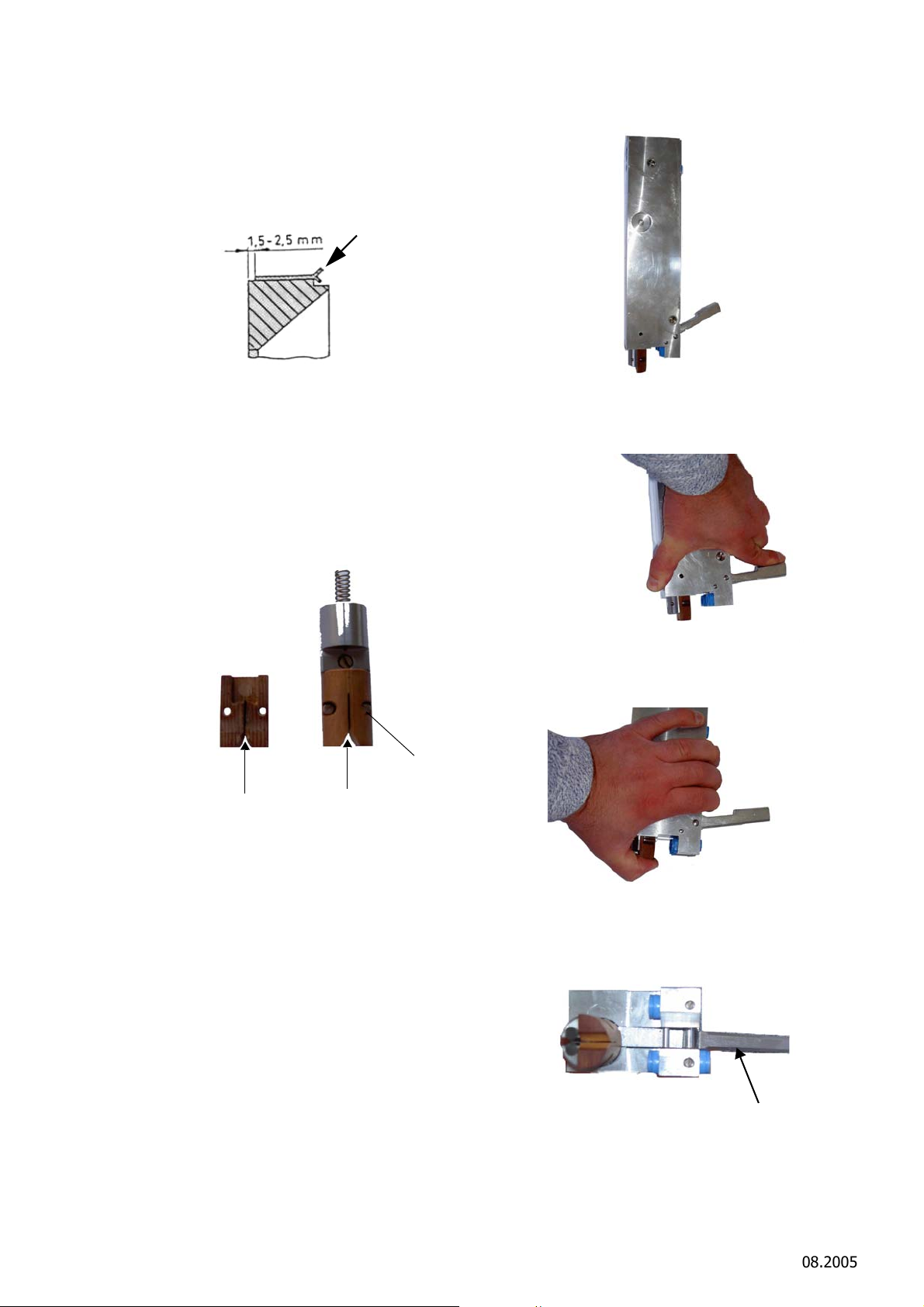
Open the lids (B), see chapter 4.1.1
Free rotation
Gap width max. 2.0 New: 0.6 mm
Fibre guide
Lever (64)
"Dismantling saw band" (page 6).
Tighten the saw band, see chapter 4.1.2
"Changing saw band" (page 6).
Complete guide mechanism
Figure 6: Distance between drive/guide wheel to
saw band
Changing guide
The figure shows the bar of model SB295; the procedure for changing the guide mechanism is the
same for models SB287, SB288 and SB295
If the gap is wider than 2. mm, change the fibre
guide (see figure 7).
Figure 7: Changing guide
Figure 8: Guide
1. Push guide up.
Figure 9: Guide pushed up
2. Hold guide in top position.
Removing guide from strip
To remove the guide from the strip, proceed as
follows:
Schmid & Wezel
D75433 Maulbronn,
3. Remove the lever (64) from the holder.
Page / Seite
7 / 27
Figure 10: Guide in top position
Version / Ausführung
08.2005
Page 22
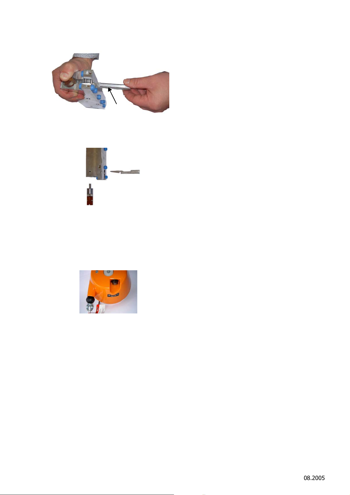
Figure 11: Lever (64)
Lever (64)
Figure 12: Removing lever from holder
4. Dismantle the guide and lever.
Figure 13: Dismantling guide and lever
4.3 Adjusting spring-loaded pulley
The spring-loaded pulley can be adjusted by turning
the PLUS/MINUS screw at the housing (see figure
14).
Figure 14: Spring-loaded pulley
Turn the screw in MINUS direction until the tool
is balanced and suspended at the correct
height.
If it is not possible to pull more cable from the
pulley, it is jammed and must be readjusted.
Turn the screw in PLUS direction until cable can
be pulled from the pulley and repeat the fine
adjustment (see above).
5. Maintenance
Malfunctions that might occur during operation can
generally be eliminated very simply. Table 1:
"Troubleshooting" lists possible faults, their causes
and remedies.
Schmid & Wezel
D75433 Maulbronn,
Page / Seite
8 / 27
Version / Ausführung
08.2005
Page 23

Table 1: Troubleshooting splitting saw
Malfunction/fault Possible cause Remedy
1. Saw fails to start when switch
is pressed
(saw failure)
3. Saw starts when switch is
actuated, but runs without
power
Power cable break Check power supply line
In 42V model, check contactor
connection
Microswitch (6) defective Check switch; replace, if
necessary
Front/rear cover not properly
closed, or not in proper position
Power supply line not properly
connected to terminals
Motor winding defective Dismantle motor, check winding;
Electrical connection of
microswitch (6) disconnected at
front operating lever or terminal
Power line cross-section or
lengths too small
Check covers and close to
establish contact
Check terminals and reconnect/
retighten
replace, if necessary
Reconnect or replace cable or
microswitch
Check dimensions according to
Anhang A.3.5
"Leitungsquerschnitte/ Crosssections of lines" (S. 18) and
change, if required
Voltage drop in supply network Establish cause of voltage drop
Saw band insufficiently tightened Retighten with torque wrench
4. Saw sometimes fails to start
when switch is actuated or
starts/shuts down with a delay
5. Excessive band wear Guide plate of the front guide
Cables loose at the terminal Check terminals and eliminate
wheel is secured too tightly or
jammed
Tightened with incorrect torque Check with torque wrench
and eliminate it (if required, use
Schmid and Wezel testing
equipment)
problem
Check for free movement; if
necessary, release with the
torque wrench and lubricate
(torque too high)
Schmid & Wezel
D75433 Maulbronn,
Page / Seite
9 / 27
Version / Ausführung
Page 24

Table 1: Troubleshooting splitting saw
6. Saw cut frayed Saw band guide mechanism worn See chapter 4.2 "Saw band
guides" (page 6)
Strip (front or rear) holding the
guide worn out, so that the guide
is in an inclined position
The bolt of the suspension of
band saw is worn, causing the
saw to be suspended at an angle
Band positioned incorrectly, no
tooth set
Guide wheel at front or rear worn Check wheels; replace, if
7. Band jumps from wheel Guide wheel at front or rear worn Check wheels; replace, if
Band tightening torque too low Retighten band with the torque
Wheel ball bearings (front/rear)
worn out
Frame misaligned Cannot be repaired; purchase
Replace strip; always replace the
strips in pairs (front and left)!
Correct suspension or replace
bolt
Insert band so that the teeth face
the motor, see chapter 4.2 "Saw
band guides" (page 6)
necessary
necessary
wrench
Check bearing play; replace
bearings, if necessary
new frame and remount
individual parts
8. No water during cleaning
(saw)
9. No water during cleaning
(operation)
Connection of solenoid valve
loose Check hose; replace, if necessary
Solenoid valve defective Check valve; replace, if necessary
Nozzles or water pipe blocked by
limestone or dirt
Water connection defective or
loose Check hose; replace, if necessary
Water hose not connected or
supply system defective
Clean parts; replace, if necessary
Check and repair
Schmid & Wezel
D75433 Maulbronn,
Page / Seite
10 / 27
Version / Ausführung
Page 25
6. Cleaning and maintenance
Before carrying out any cleaning or
maintenance work, disconnect the
splitting saw from the supply
network!
Before carrying out any
maintenance work, open the
covers (B) (switch-on protection)
to prevent inadvertent restart!
Do not use aggressive detergents!
Do not clean with steam or highpressure water jet! Do not
immerse machine in water!
6.1 Daily cleaning at shift end
For disruption-free operation, ensure that the
splitting saw is always kept clean. Disinfect tool
before cleaning it.
Always comply with the relevant safety and hygiene
requirements (DIN EN 1672)!
Ensure that disinfectants are not brought into
contact with food, whether directly or indirectly.
Rinse tool thoroughly with water to remove all
disinfectant.
Diversey Lever GmbH
Mallaufstr. 50-56, 68219 Mannheim, Germany
Alternat ive product:
P3-topax 91:
surface-active disinfectant
Henkel-Ecolab Deutschland GmbH, Postfach 13
04 06, D-40554 Düsseldorf, Germany
For a cleaning schedule and detailed instructions,
contact the above suppliers.
The detergents listed above are recommended
products. If you wish to use other products, you are
obliged to test them as regards suitability and
compliance with the applicable hygiene regulations.
6.1.3 Lubricants
The lubricant must meet the requirements of the
relevant regulations (DIN 1672) as regards
suitability for use in food processing.
Recommended gear lubricant
Klübersynth UH1 12-1600 (H1)
EFA special grease
Order no. 001 365 644 (0.8 kg)
Order no. 001 365 645 (5.0 kg)
Quantity of lubricant for gear:
EFA SB 288 E: 600 g
6.1.1 Disinfection
During operation, disinfect the splitting saw after
each cut with hot water (82° C). If disinfection is
required, install a separate sterilisation booth (order
no. 007 009 329).
6.1.2 Cleaning of splitting saw
After each shift, release the saw band (see chapter
4.1.1 "Dismantling saw band" (page 6)), remove it
from the machine, clean it with water and dry it.
After each shift, remove the guide mechanism and
clean the boreholes (see chapter 4.2 "Saw band
guides" (page 6)).
Clean the splitting saw with a brush and cloth, using
warm water (40 - 55° C). To remove persistent or
encrusted dirt, soak the saw in warm water. Apply
detergent, possibly in the form of foam, to the
affected area and let soak for 15 to 20 minutes.
Wash with warm water.
Recommended lubricant for all lubrication
points, guides and torque wrench
Molykote Longterm W2
EFA special grease
Order no. 001 365 623 (1 kg)
Order no. 001 365 624 (5 kg)
Recommended oil for torque wrench oil bath
Shell-Ondina G17, 15 Centistok / 40°
Special oil
Order no. 001 365 611 (0.5 l)
Order no. 001 365 612 (5.0 l)
Recommended cleaning agents
Diversey Lever Tego 2000:
surface-active disinfectant
Schmid & Wezel
D75433 Maulbronn,
Page / Seite
11 / 27
Version / Ausführung
08.2005
Page 26

6.2 Daily servicing of splitting saw
Before carrying out any repair
work, disconnect the splitting saw
from the power supply!
In order to meet the hygiene requirements, the
splitting saw must be serviced after each shift.
6.2.1 Lubrication
After cleaning, apply a little EFA special oil (acid-free
product) to the saw band and lubricate the guide
mechanism with EFA grease.
6.2.2 Guide mechanism
The guide mechanism must be serviced with special
care. If there are any signs of wear, immediately
adjust it or replace it, if necessary.
Check the guide mechanism and the spring for free
movement and lubricate it.
specialist technicians.
Schmid & Wezel operates an extensive after-
sales service network. Contact your local
authorised repair shop or the Schmid & Wezel
customer service department for more
information on our services.
Please note that electric machines must be
repaired by qualified electricians as improper
repairs might lead to serious injury to the
operator.
On request, we provide spare parts lists for
repair shops with specialist technicians.
After completion of the repair work, the gear
system must be lubricated again for life!
6.2.3 Saw band
Regularly check the saw band; if worn, replace it.
6.2.4 Motor
Regularly unblock the condensate drain holes at the
bottom of the motor, using a blunt non-metal tool.
If condensate collects inside the machine, the motor
might fail (corrosion of winding), causing high repair
costs.
6.3 Overhaul service
(to be carried out every 50
operating hours)
6.3.1 Splitting saw
Check ball bearings of the guide wheels and
lubricate, if necessary.
6.3.2 Guide mechanism
Apply a little lubricant to the two guides.
6.3.3 Torque wrench
Over the weekend, place the torque wrench in an oil
bath. Do not lubricate.
6.3.4 Gear system
7. Transport and storage
The splitting saw must be stored in a dry, wellventilated room.
For transport, clean the machine as described in
chapter 6.1.2 "Cleaning of splitting saw" (page 11),
and dry it thoroughly.
During transport, protect the splitting saw against
damage from impacts, etc.
8. Return of decommissioned
equipment
For proper disposal, return your equipment to
Schmid & Wezel.
The gear is equipped with permanent lubrication.
The lubrication must however be renewed after
repairs.
6.4 Repairs by Schmid & Wezel
customer service technicians
All repairs must be completed by authorised
Schmid & Wezel
D75433 Maulbronn,
Page / Seite
12 / 27
Version / Ausführung
08.2005
Page 27

A. Anhang / Appendix
A.1 Technische Daten / Technical Data
Spannung, Frequenz Voltage, frequency 42V, 50 Hz
Motorleistung Motor rating 1900W/2,5PS
EFA SB 288 E
Stromaufnahme I
Schutzkart Protection class IP 65
Kabellänge Cable length 4 m
Gewicht Weight 50 kg
Sägebandlänge Saw-belt length 2904 mm
Schnittzeit pro Tier Cutting time animal 20-25 s
Betriebsdruck (Wasser) Working pressure 2-5 bar
Wasseranschluss Water supply 1/2“ Schlauch/
Wasserschlauch Watertube max. 20l/min
Hand-Arm-Vibration (EN 28662) Hand-arm vibration
Schalldruckpegel (EN 50 144) Sound pressure level < 83 dB(A)
Auch in Sonderspannungen 115 V, 50 Hz und 230 V/400 V, 50 Hz sowie in 60 Hz lieferbar.
Also available for special voltages 115 V, 50 Hz and 230/400 V, 50 Hz or 60 Hz.
nenn
Current consumption 17 A
Magnetventil
< 2,5 m/s
2
Schmid & Wezel
D 75433 Maulbronn
Seite/ Page
13/ 27
Ausführung/ Execution
03.2008
Page 28
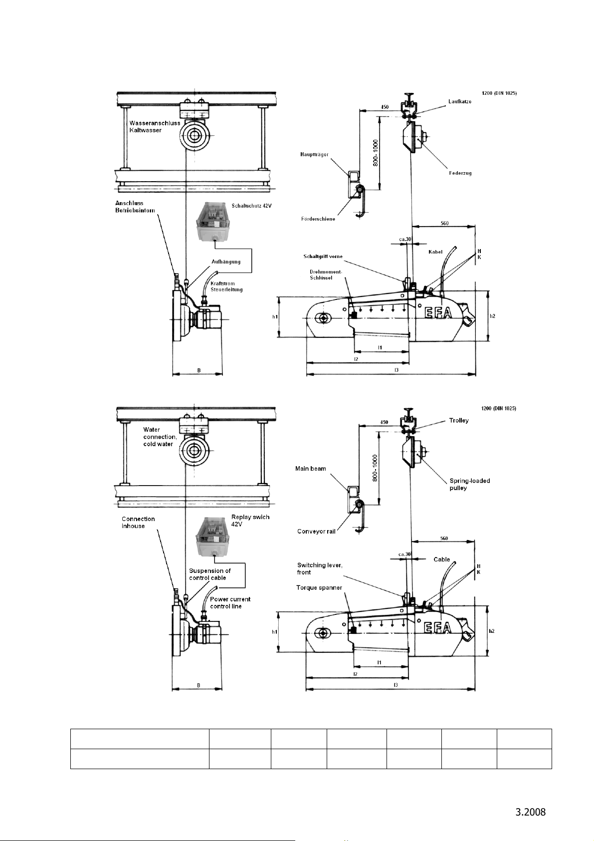
A.2 Maschinen-Komponenten / Machine Components
Anschluss der Steuerung, siehe Schaltpläne / For details of the control system connections, see separate circuit
diagramm.
Maße/ Dimensions [mm] B h1 h2 l1 l2 l3
EFA SB 288 E 355 310 410 467 887 1440
Schmid & Wezel
D 75433 Maulbronn
Seite/ Page
14/ 27
Ausführung/ Execution
3.2008
Page 29
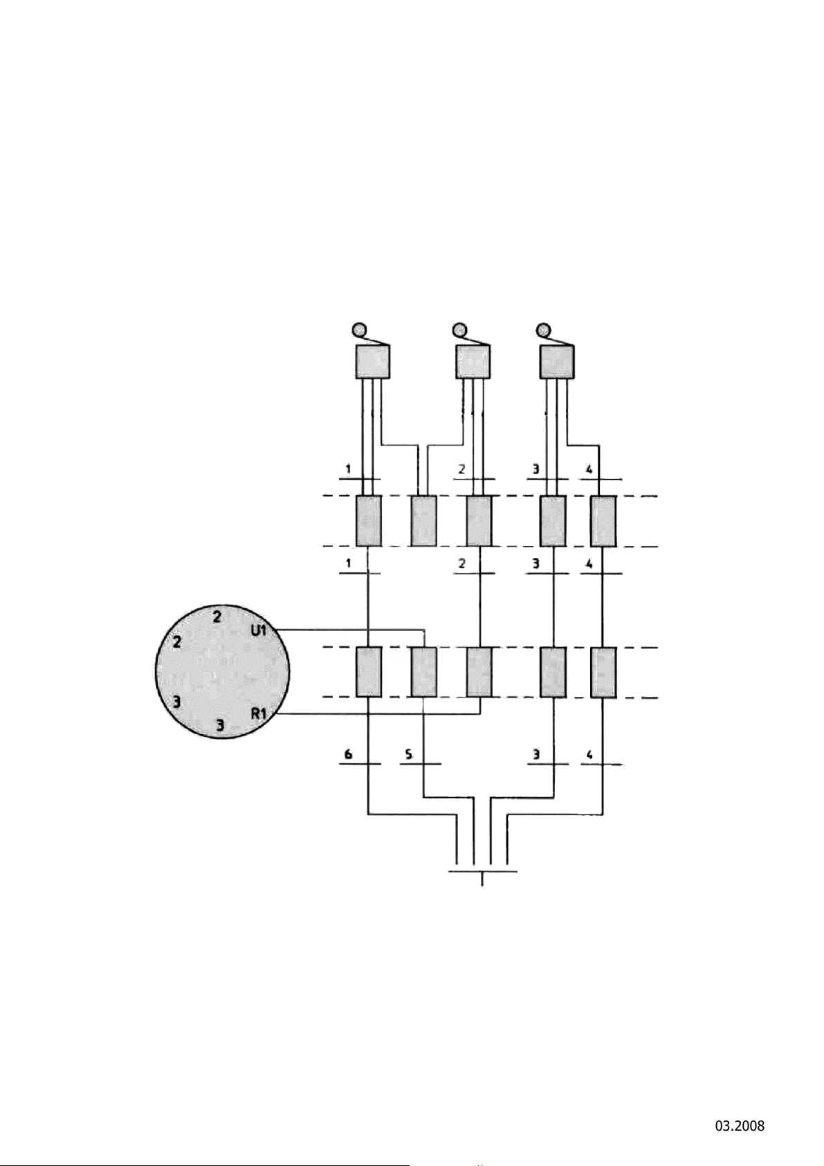
A.3 Schaltpläne / Circuit Diagrams
Steuerkanal/
Control cable
Deckelsicherung/
Cover lock
Handgriff/
Handle
Klemmen/
Terminals
Klemmen/
Terminals
A.3.1 Deckelsicherung EFA SB 288 E/ Cover lock EFA SB 288 E
Schmid & Wezel
D 75433 Maulbronn
Seite/ Page
15/ 27
Ausführung/ Execution
03.2008
Page 30
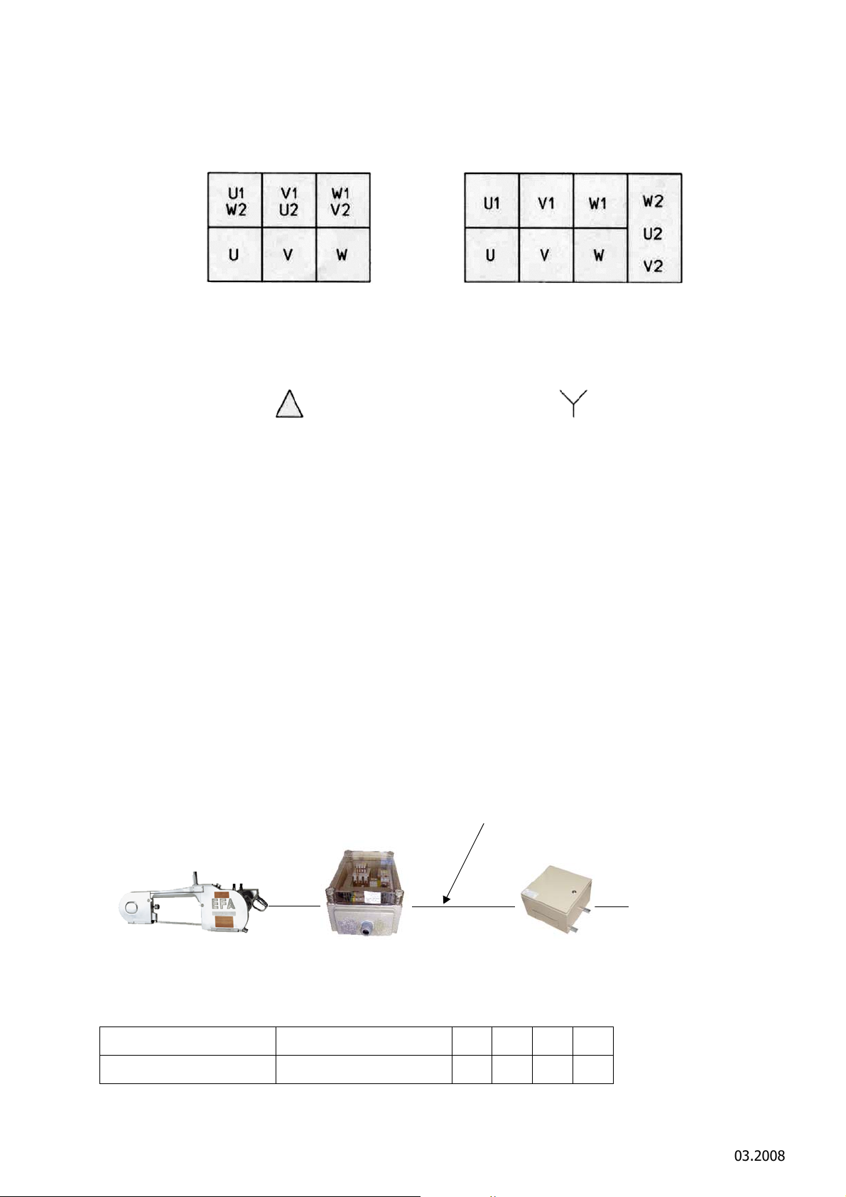
A.3.2 Motorklemme/ Motor terminal
230 V 3 Phasen/3-phase 400 V 3 Phasen/3-phase
Netz/ Mains
Motorschaltung/
Motor circuit
Netz/ Mains
Motorschaltung/
Motor circuit
Netz/ Mains
Säge/ Saw
Schaltschütz/Relay switch
Trafo/ Transformer
Zuleitung L/ Supply line L
A.3.3 Schaltschütz/ Relay switch
Schaltpläne für den schaltschütz liegen im Steuerungskasten innen./
The circuit diagrams of the control system are in the control box.
Bei Bedarf können diese von Schmid & Wezel separat geliefert werden./
If you require additional copies of the diagrams, please contact us, quoting the following order numbers:
Artikelnummer/ Product no. 001 604 101 (42V)
A.3.4 Leitungsquerschnitte/ Cross-sections of lines
Leitungsquerschnitt der Zuleitung ( Länge L)
zwischen Transformator und Steuerungskasten.
Querschnitt ( A) 3-adrig erforderlich. Leitungsmaterial: Kupfer
The following specifications refer to line L
between the transformer and the control box.
Cross-section (A) must consist of 3 wires. Conductor material: copper
SB 288 E
Leitungslänge bis... m Length of line max. ...m 4,5 8,5 13 23
Querschnitt (mm²) Cross-section (mm²) 6 10 16 25
Schmid & Wezel
D 75433 Maulbronn
Seite/ Page
16/ 27
Ausführung/ Execution
03.2008
Page 31

A.4 Zubehörliste EFA SB 288 E / List of accesories EFA SB 288 E
A.4.1 Zubehör im Lieferumfang enthalten / Accesories, included in scope of supply
Pos.
Fig.
ohne
Abbildung
not
illustrated
ohne
Abbildung
not
illustrated
Stück
Benennung Designation Best.-Nr.
Pcs.
1 Drehmomentschlüssel Torque wrench 001 963 363
1 EFA-Spezialfett Special grease 001 365 618
Sonderzubehör / Special Accessories
Pos.
Fig.
ohne
Abbildung
not
illustrated
ohne
Abbildung
not
illustrated
Stück
Benennung Designation Best.-Nr.
Pcs.
1 Schaltschutz 42V Relay switch 42V 001 604 101
1 Federzug Spring balancer 001 620 053
Order No.
Order No.
ohne
Abbildung
not
illustrated
ohne
Abbildung
not
illustrated
ohne
Abbildung
not
illustrated
ohne
Abbildung
not
illustrated
1 Magnetventil für automatisch
Wasser ein/ aus 42 V
1 Magnetventil für automatisch
Wasser ein/ aus 400 V
electrovalve for automatic
Waterflow on/off 42 V
electrovalve for automatic
Waterflow on/off 400 V
008 009 821
008 009 822
1 Transformator 3000 VA / 42V Transformer 3000VA / 42V 001 604 507
1 Schiebelaufkatze Trolley rugged design 001 950 252
Anzugsmoment Torque Pos./Fig.
Sechskantschraube Hexagon screw (32) 8 Nm
Senkschraube Contersunk screw (36) 30 Nm
Sechskantschraube Hexagon screw (45) 15 Nm
Lagerbolzen Bearing bolt (56) 100 Nm
Sechskantmutter Hexagon nut (71) 100 Nm
Gewindestift Threaded pin (63) 6 Nm
Schmid & Wezel
D 75433 Maulbronn
Seite/ Page
17/ 27
Ausführung/ Execution
03.2008
Page 32
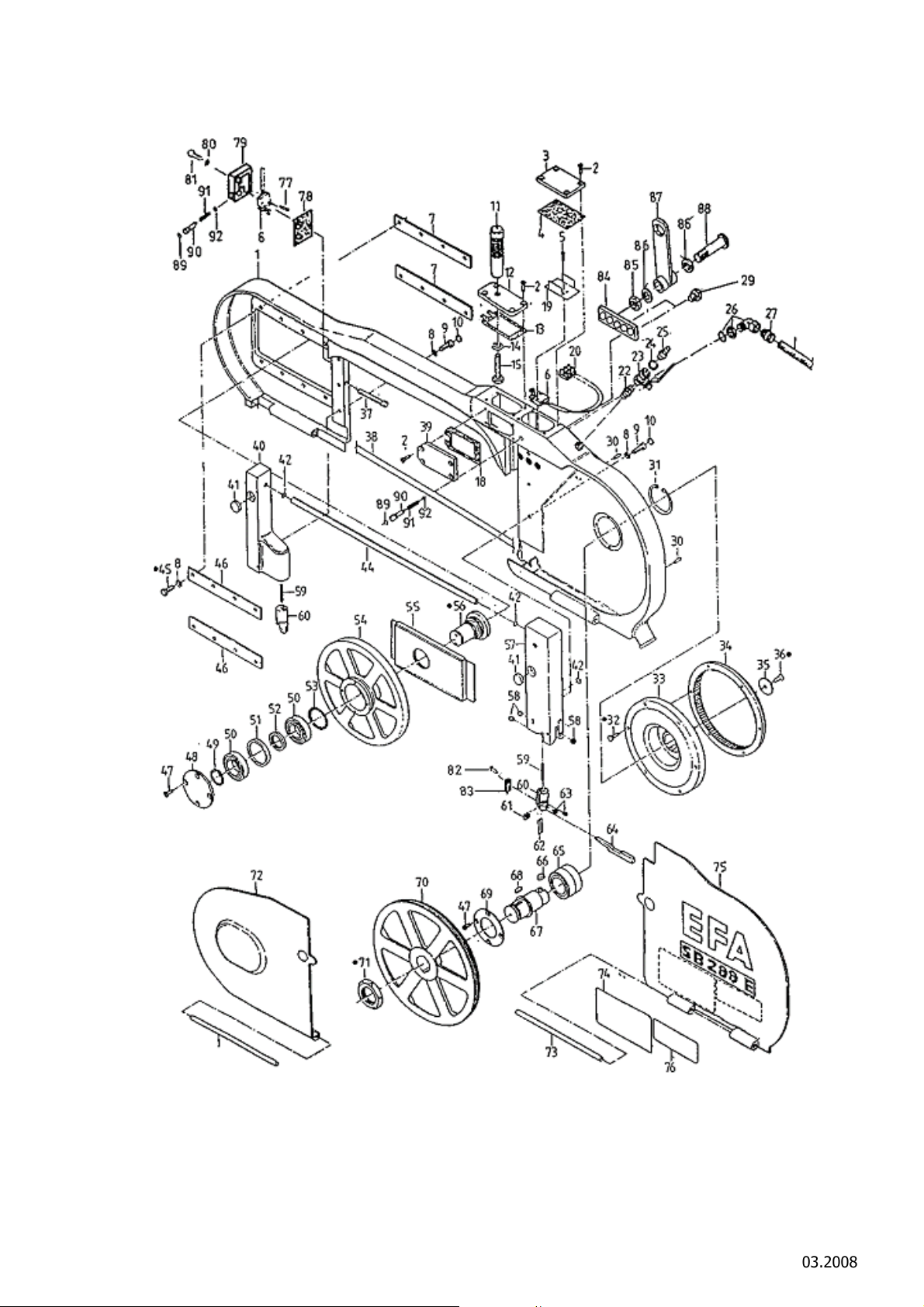
A. 5Ersatzteilliste EFA 288 E / Sparepart list EFA 288 E
Schmid & Wezel
D 75433 Maulbronn
Seite/ Page
18/ 27
Ausführung/ Execution
03.2008
Page 33

Pos.
Fig.
10 6 Verschlußstopfen Vent plug 001 368 634
11 1 Griff Handle 002 000 303
12 1 Deckel Cover 003 009 490
13 2 Dichtung Seal 003 009 206
Stück
Pcs.
1 1 Gehäuse, vollst. Housing, complete 007 009 722
2 12 Schraube mit Schlitz Countersunk screw 001 326 406
3 1 Deckel Cover 003 009 239
4 1 Dichtung Seal 003 009 241
5 4 Zylinderschraube mit Schlitz Cylinder screw 001 326 111
6 2 Mikro-Schalter Micro-switch 001 601 215
7 2 Führungsleiste Guide ledge 003 006 939
8 15 Federring Spring washer 001 317 003
9 6 Zylinderschraube Cylinder screw 001 326 019
Benennung Designation Best.-Nr.
Order No.
14 1 Federring Spring washer 001 317 004
15 1 Sechskantschraube Hexagon screw 001 325 909
19 1 Isolierteil Insulating part 003 009 291
20 1 Lüsterklemme Terminal strip 001 605 016
22 1 Doppelnippel Double nipple 001 606 516
23 1 Kugelhahn Ball valve 001 362 005
24 1 Dichtring Packing ring 001 313 102
25 1 Außengewindetülle Externally threaded sleeve 001 366 205
26 1 Winkelkabelverschraubung Cable screw joint 001 325 514
27 1 Kabelverschraubung Hose screwing 001 325 556
28
29 2 Sechskantschraube Hexagonal screw 003 009 676
30 2 Zylinderstift Cylinder pin 001 307 218
31 1 Sicherungsring Snap ring 001 312 356
32 6 Sechskantschraube Hexagon screw 001 325 999
1 K
unststoffschlauch Plastic hose 001 330 391
33 1 Träger Support 003 007 794
34 1 Metallzahnrad Metal gear whee 003 005 383
35 1 Scheibe Disk 003 007 806
36 1 Senkschraube Countersunk screw 001 326 506
Schmid & Wezel
D 75433 Maulbronn
Seite/ Page
19/ 27
Ausführung/ Execution
03.2008
Page 34

37 1 Spannschraube Locking screw 003 008 941
38 1 Sägeband Saw band 001 363 702
39 1 Deckel Cover 003 009 342
40 1 Leiste, vollst. Ledge, complete 007 009 726
41 2 Haftmagnet Magnet 002 000 306
42 3 O-Ring O-ring 001 312 662
44 1 Wasserrohr Water pipe 003 009 254
45 12 Sechskantschraube Hexagon screw 001 325 914
46 2 Führungsleiste Guide ledge 003 006 436
47 8 Senkschraube Countersunk screw 001 326 402
48 1 Deckel Cover 003 009 238
49 1 Sicherungsring Snap ring 001 312 432
50 2 Rillenkugellager Ball bearing 001 345 330
51 1 Distanzring Distance ring 003 006 725
52 1 Distanzring Distance ring 003 006 724
53 1 Dichtring Packing ring 001 344 236
54 1 Leitrollenrad vorne Idler wheel, front 003 009 137
55 1 Führungsplatte Guide plate 003 009 231
56 1 Lagerbolzen Bearing bolt 003 009 232
57 1 Leiste, vollst. Ledge, complete 007 009 727
58 12 Vollkegeldüse Jet complete 001 610 223
2 Halter vollst, (bestehend aus
59,63,82 u. 83)
59 2 Druckfeder Pressure spring 001 362 674
60 2 Halter Holder 003 009 235
61 2 Hartmetallplatte Cemented carbide plate 002 000 259
62 4 Hartmetallführung Cemented carbide guide 003 009 255
63 2 Gewindestift Threaded pin 001 326 302
64 2 Hebel vst. Flipper molded 007 009 835
65 2 Kegelrollenlager Special ball bearing 001 345 803
Holder complete 007 009 235
66 2 Paßfeder Key 001 305 459
67 1 Antriebswelle Motorshaft 003 009 245
68 2 Paßfeder Key 001 305 415
69 1 Deckscheibe Cover plate 003 009 240
70 1 Leitrollenrad, hinten Idler wheel, rear 003 009 136
Schmid & Wezel
D 75433 Maulbronn
Seite/ Page
20/ 27
Ausführung/ Execution
03.2008
Page 35

71 1 Sechskantmutter Hexagon nut 003 009 246
72 1 Deckel, vollst. Cover, complete 007 009 725
73 2 Bolzen Bolt 003 009 236
74 1 Hinweisschild Indicating label 003 006 949
75 1 Deckel, vollst. Cover, complete 007 009 724
76 1 Hinweisschild Indicating label 003 005 151
77 2 Zylinderschraube mit Schlitz Cylinder screw 001 326 117
78 1 Dichtung Seal 003 009 548
79 1 Gehäuse Housing 003 009 547
80 2 Federring Spring washer 001 317 002
81 2 Sechskantschraube Hexagon screw 001 325 920
82 4 Zylinderschraube mit Schlitz Cylinder screw 001 326 118
83 2 Fiberführung Fiber guide 003 009 634
84 1 Halter Holder 003 009 677
85 1 Sechskantmutter Hexagon nut 001 300 248
86 2 Scheibe Disk 001 310 510
87 1 Aufhängehebel Hanger arm 003 009 251
88 1 Gewindebolzen Threaded bolt 003 009 252
89 2 O-ring O-ring 001 312 642
90 2 Bolzen Bolt 003 009 168
91 2 Druckfeder Pressure spring 001 362 640
92 2 Sicherungsring Snap ring 001 312 405
Schmid & Wezel
D 75433 Maulbronn
Seite/ Page
21/ 27
Ausführung/ Execution
03.2008
Page 36
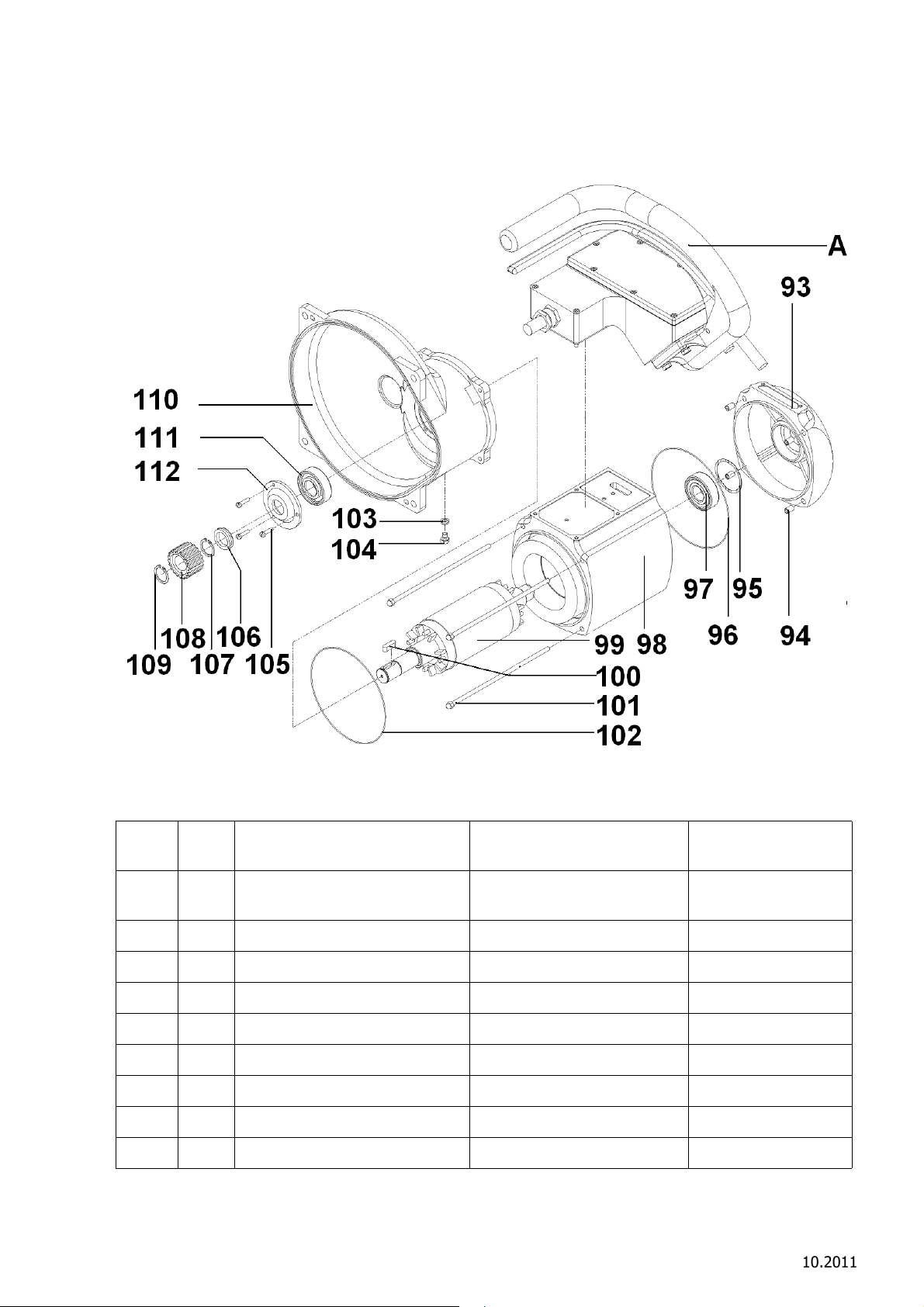
Pos.
Fig.
Stück
Pcs.
Benennung Designation Best.-Nr.
Order No.
A 1 Handgriff kpl. (siehe seperate
Ersatzteilliste S.25)
98 1 Motor vst. 42V (P
Motor vst. 230/400V Motor 230/400V 007 012 003
93 1 Lagerschild End plate 003 011 854
95 1 Wellenfederring Spindle spring washer 001 314 604
96 1 O-Ring O-ring 001 317 778
97 1 Rillenkugellager Ball bearing 001 345 316
99 1 Rotorachse vst. Rotor 007 011 853
100 1 Passfeder Spring washer 001 305 415
Schmid & Wezel
D 75433 Maulbronn
os. 93-102)
Hand grip (see on seperate
spare-part list P.25)
Motor 42V (Fig. 93-102) 007 012 001
Seite/ Page
22/ 27
008 011 340
Ausführung/ Execution
10.2011
Page 37

101 4 Senkkopfschraube Counter head screw 001 326 423
102 1 O- Ring O- ring 001 312 689
103 1 Entlüftungsschraube Air vent plug 002 000 328
104 1 Unterlegscheibe Washer 001 315 002
105 3 Zyl. Schraube mit Schlitz Cylinderbolt 001 326 102
106 1 V- Ring V- ring 001 316 408
107 1 Sicherungsring EFA Gasket ring 001 312 417
108 1 Antriebsrad EFA Drive gear 003 004 112
109 1 Sicherungsring EFA Gasket ring 001 312 417
110 1 Gehäuse Housing 003 007 792
111 1 Rillenkugellager EFA Ball bearing 001 340 238
112 1 Lagerdeckel Bearing cover 003 011 830
Schmid & Wezel
D 75433 Maulbronn
Seite/ Page
23/ 27
Ausführung/ Execution
03.2008
Page 38
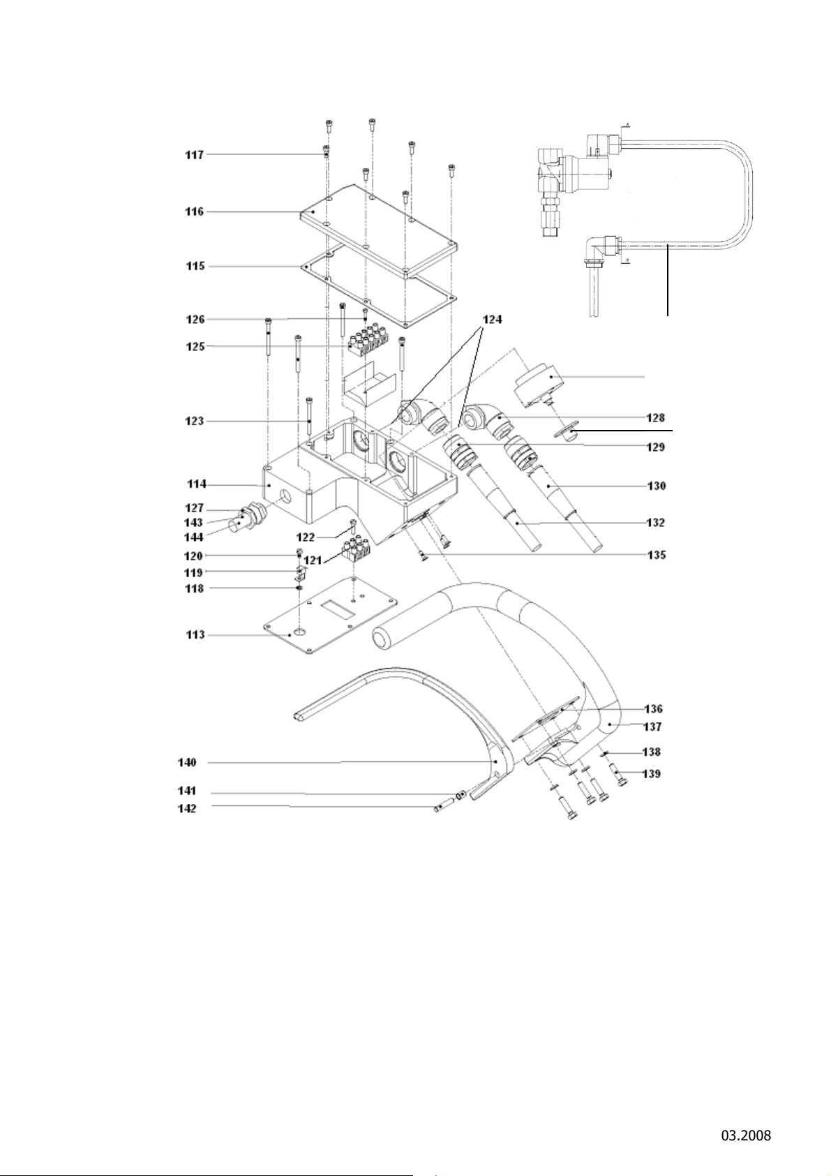
134
133
131
Schmid & Wezel
D 75433 Maulbronn
Seite/ Page
24/ 27
Ausführung/ Execution
03.2008
Page 39

Pos.
60
Fig.
113 1 Dichtung EFA EFA Sealing 003 011 856
114 1 Schalterkasten vst. Switch box 007 009 258
115 1 Dichtung Sealing 003 004 107
116 1 Deckel Cover 003 004 108
117 7 Zylinderschraube m. i. skt Cylinderbolt 001 326 003
118 1 Unterlegscheibe Washer 001 317 007
119 1 Klemme Clamp 001 605 601
120 1 Zylinderschraube m. i. skt Cylinderbolt 001 326 101
121 1 42V Klemme 4-polig 42 V 4 pole clamp 001 605 006
122 2 Zylinderschraube m. Schlitz Cylinderbolt 001 326 112
123 5 Zylinderschraube m. i. skt Inner hexagon cyl. bolt 001 326 010
124 2 Reduzierung Reduction 001 604 009
Stück
Pcs.
1 400V Klemme 3 polig 400 V 3 pole clamp 001 605 008
Benennung Designation Best.-Nr.
Order No.
125 1 Klemme 5-polig 230/400V 5-pole clamp 230/400V 001 605 001
126 1 Zylinderschraube m. Schlitz Cylinderbolt 001 326 117
127 1 Kabelverschraubung Cable gland 001 325 556
128 1
1 Winkelverschraubung 230/400V Elbow 230/400V 001 325 543
129 1 Kabelverschraubung 42V Cable connection 42V 001 325 531
1 Kabelverschraubung 230/400V Cable connection 230/400V 001 325 526
130 1 Knickschutztülle 230/400V Bend protection 230/400V 003 001 544
131 1 Magnetventil 42V Magnetic valve 42 008 009 821
132 1 Gummischlauchleitung 42V Rubber hose 42V 001 601 704
1 Gummischlauchleitung 230/
133 1 Ausschalter EFA Cut out 001 601 206
Winkelv
Magnetventil 230/400V Magnetic valve 230/400V 008 009 822
Magnetventil 230V 60Hz Magnetic valve 230V 60Hz 008 011 217
400V
erschraubung 42V Elbow 42V 001 325 544
Rubber hose 400V 001 601 702
134 1 Abdeckkappe Cover 003 002 454
135 3 Senkschraube m. i. skt Counter head screw 001 326 501
136 1 Dichtung EFA Gasket 003 007 630
137 1 Schaltergriff Controller 003 010 266
138 4 Federring Spring washer 001 317 002
Schmid & Wezel
D 75433 Maulbronn
Seite/ Page
25/ 27
Ausführung/ Execution
3.2008
Page 40

139 4 skt. Schraube Hexagon screw 001 325 913
140 1 Schalterhebel vst. Switcher 007 010 267
141 1 Gleitlager. Sliding bushing 001 346 022
142 1 Zylinderstift Cylinderbolt 001 307 217
143 1 Gummischlauchleitung Rubber hose 001 601 742
144 1 Kunststoffschlauch 280mm Flexible hose 001 330 389
Schmid & Wezel
D 75433 Maulbronn
Seite/ Page
26/ 27
Ausführung/ Execution
03.2008
Page 41
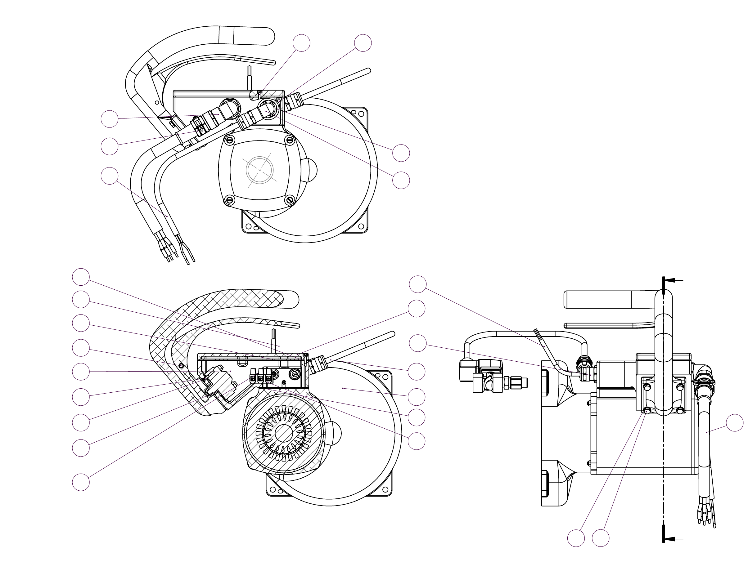
11
Motor kpl. 008014450
12
Anzugsm. 2 Nm
6 9
10
24
14
15
16
26
25
B
8
3
7
Anzugsm. 2 Nm
Anzugsm. 2 Nm
20
13
21
19
5
SCHNITT B-B
23
1
2
4
17
22
18
B
Anzugsm. 6,5 Nm
Page 42

Pos.Nr.
Artikelnummer
Benennung
Menge
1 007012001
2 003011856
3 007014450
4 001605009
5 001326112
6 001326003
7 001325556
8 001601742
9 001326010
10 001604009
11 001325544
12 001325531
13 003007630
Motor vst.
Dichtung
Schalterkasten vst.
Klemmleiste
Zylinderschraube
Zylinderschraube
Kabelverschraubung
Kabel
Zylinderschraube
Reduzierung
Winkelverschraubung
Kabelverschraubung
Dichtung
1
1
1
1
1
4
2
1
5
1
1
1
1
14 003010266
15 007010267
16 001307217
17 001317002
18 001325913
19 003002454
20 001601206
21 001326501
22 001601760
23 008009821
24 003004107
25 001325543
26 001601781
Schaltergriff
Schalterhebel vst.
Zylinderstift
Federring
Sechskantschraube
Abdeckkappe
Schalter
Senkschraube
Kabel
Magnetventil kpl.
Dichtung
Winkelverschraubung
Kabel
1
1
1
4
4
1
1
3
1
1
1
1
1
Page 43
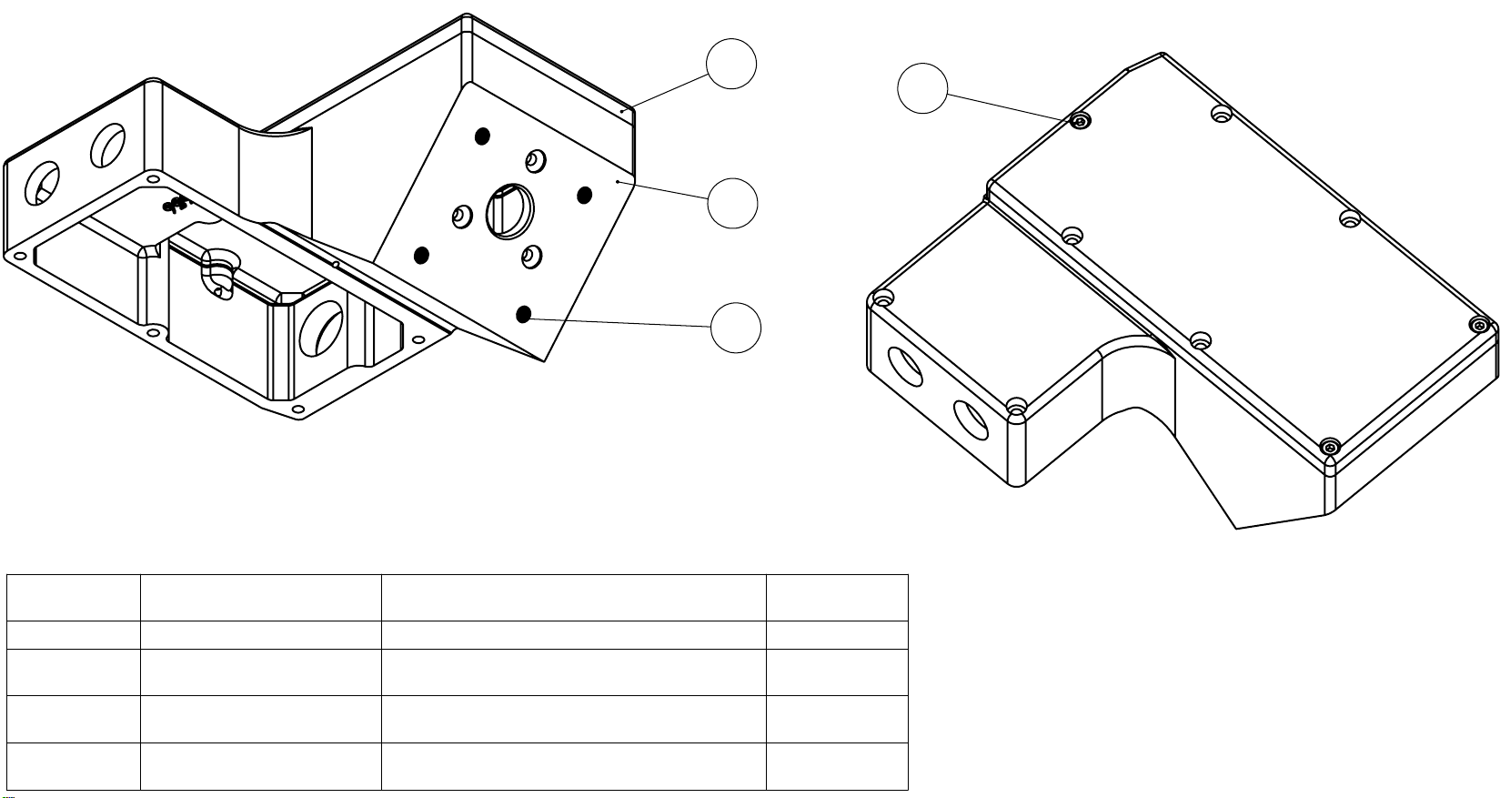
40
Schaltkasten vst. 007014450
30
10
20
POS-NR.
Artikelnummer
10 001316021
20 001326003
30 003014450
40 883004108
Benennung
Gewindeeinsatz
Zylinderschraube
Schalterkasten
Deckel
Standard/
MENGE
4
3
1
1
 Loading...