

Page 1

Magellan EBX
(E6BX-ATX)
AGP/ PCI/ ISA/ IO
Mother Board
User’s Manual
PART NO. M533G00200 Rev 1.0 MAY. 1998
Page 2

TABLE OF CONTENTS
1. SPECIFICATION …………………………………………. 2
2. Jumper & Memory Setting …………………………. 3
2.1 CPU Jumper Setting …………………………………………….. 3
2.2 Special Function Jumpers ……………………………………. 3
2.3 Multifunction Connector ……………………………………… 4
2.4 Memory Size……………………………………………………….. 4
2.5 SEC of CPU …………………………………………………………. 4
2.6 Installing the Pentium II processor …………………………. 7
2.7 Chart Of Jumper …………………………………………………. 8
3. AWARD BIOS SETUP…………………………………….. 9
3.1 BIOS Setup ………….……………………………………………… 9
3.2 Standard CMOS Setup ………………………………………….. 10
3.3 BIOS Features Setup …………………………………………….. 13
3.4 Chipset Features Setup..……………………………………….. 15
3.5 Power Management Setup……………………………………. 17
3.6 PNP/PCI Configuration Setup …………………………………. 20
3.7 Load BIOS Defaults ………………………………………………. 21
3.8 Load Setup Defaults ……………………………………………. 21
3.9 Integrated Peripherals ………………………………………… 21
3.10 Supervisor Password and User Password …………………. 23
3.11 IDE HDD AUTO Detection ………………………………………. 23
3.12 Save and Exit Setup …………………………………………….. 24
3.13 Exit Without Saving …………………………………………….. 24
________________________________________________________________________________________
E6BX-ATX M/B Manual
Page 1
Page 3

SPECIFICATIONS
1. E6BX-ATX SPECIFICATIONS
CPU
BIOS
MEMORY
ON BOARD
I/O
GREEN
SLOT
USB
MOUSE
KEYBOARD
OTHERS
CPU
CPU Speed
System Speed
BIOS
BIOS ROM
DRAM Size
DRAM Module
I/O Function
SYSTEM
VGA
Expansion Slot
AGP
Slot 1
Keyboard CNN
Main Chipset
I/O Chipset
PCB Size
Intel Pentium II / Intel Celeron / Deschutes
233/266/300/333/350/400/450MHz
66/100MHz
128K BIOS; PnP Compliant
Flash Memory
From 8M up to 384M Bytes
DIMM x 3 of 168 Pins
Data Path 64 Bit Wide
Local Bus Enhanced Dual-Channel IDE
Bus Master PCI IDE / Mode 4, Ultra DMA-33
Support
ECP/EPP Parallel Port
2 Serial Ports
IR Function (Optional)
FDD Support
2 PnP DMA Channel Steering Via BIOS
SMM Control, Stop CPU Clock
Control Of DPMS
16 Bit ISA x 3
32 Bit PCI x 4 (4 Master Support)
1 AGP
For Pentium II, Celeron and Deschutes CPUs
Two USB Ports
PS/2 Mouse
PS/2 Keyboard
INTEL 82440BX AGPset
PIIX4x1
Winbond W83977TF, Keyboard &
PS/2 Mouse Boot Support (optional)
PCI Bus Master IDE Embedded Via PIIX4
305mm x 180mm x 1.6mm, 4 layers
Page 2 E6BX-ATX M/B
Manual
Page 4

2. Jumper & Memory Setting
2.1 CPU Jumper Setting
CPU SPEED (JP7) 1-2 3-4 5-6 7-8
450MHz
400MHz
350MHz
333MHz
300MHz
266MHz
233MHz
166MHz
2.2 Special Function Jumpers
Jumper Number FUNCTION
COM1
COM2
FAN1
FAN2
FAN3
P1
IR1
USB1
PRT1
JP1
JP2
JP3
JP5
J1
J2-P2/4/6/8
J2-P1/3/5/7/9
J2-P13/14
J2-P15/16
J2-P17/18
J3
FDD
IDE1
IDE2
1-2 SUPPORT K/B BOOT FUNCTION
2-3 NORMAL
1-2 NORMAL
2-3 CLEAR CMOS
SECONDARY HDD CONNECTOR
JUMPER SETTING
OFF ON OFF ON
OFF ON ON ON
ON OFF OFF ON
OFF OFF ON ON
OFF ON OFF ON
OFF ON ON ON
ON OFF OFF ON
ON ON OFF ON
COM1
COM2
POWER FAN
CPU FAN
SYSTEM FAN
ATX POWER CONNECTOR
IR PORT
USB PORT
PRINT PORT CONNECTOR
RESERVED
CMOS SELECT
RESERVED
ATX-POWER SWITCH BUTTON
SPEAKER CONNECTOR
POWER LED & KEYLOCK
EXTERNAL SMI SWITCH
HDD LED
RESET SWITCH
LAN CARD BOOT UP
FDD CONNECTOR
PRIMARY HDD CONNECTOR
________________________________________________________________________________________
E6BX-ATX M/B Manual
Page 3
Page 5
JUMPER SETTING
2.3 Multifunction Connector
Power LED/Key Lock Ext_SMI Reset
Speaker HDD
2.4 Memory Size
ll168 PIN DIMM
Option Type
DIMM1/2/3
NOTE :
1 The DRAM interface supports 8 Mbytes to 384 Mbytes. For
access time DIMM , you must use 60ns or less.
2 DIMM1/2/3 support 168pin 3.3v Sync. Mode DRAM.
8M, 16M, 32M, 64M, 128M
2.5 Single Edge Contact CPU
This motherboard provides a Single Edge Contact (SEC) slot for a
Pentium II processor packaged in an SEC cartridge. The SEC slot is not
compatible with other non-Pentium II processors.
Before your begin:
Use a system case with either the power supply fan or a secondary
fan circulating air across the SEC cartridge’s passive heat sink.
WARNING: Without sufficient air circulation the SEC cartridge may
overheat and cause damage to both the SEC cartridge and the
motherboard.
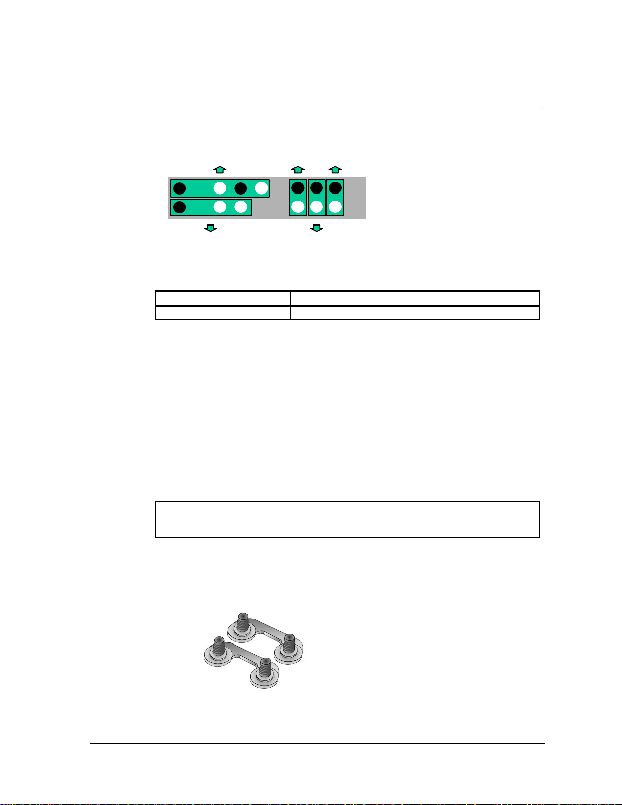
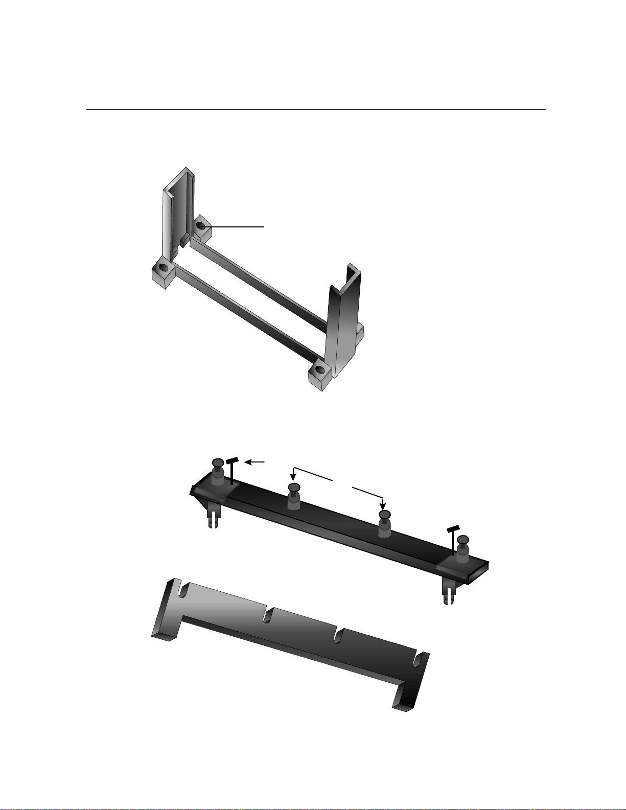
You should check to see that you have the following 8 items. (NOTE: The
images in the following pages will have the same item number next to
them for your reference.
Attachtta
Attach Mount Bridges (Items 1 and 2)
Page 4 E6BX-ATX M/B
Manual
Page 6
Captive Nut
JUMPER SETTING
(3)
Pentium II Retention Module (item3)
(5)
pin
post
(6)
Base (7)
Top Bar (4)
________________________________________________________________________________________
E6BX-ATX M/B Manual
Page 5
Heat Sink Support Base Top Bar (item4-7)
Page 7
JUMPER SETTING
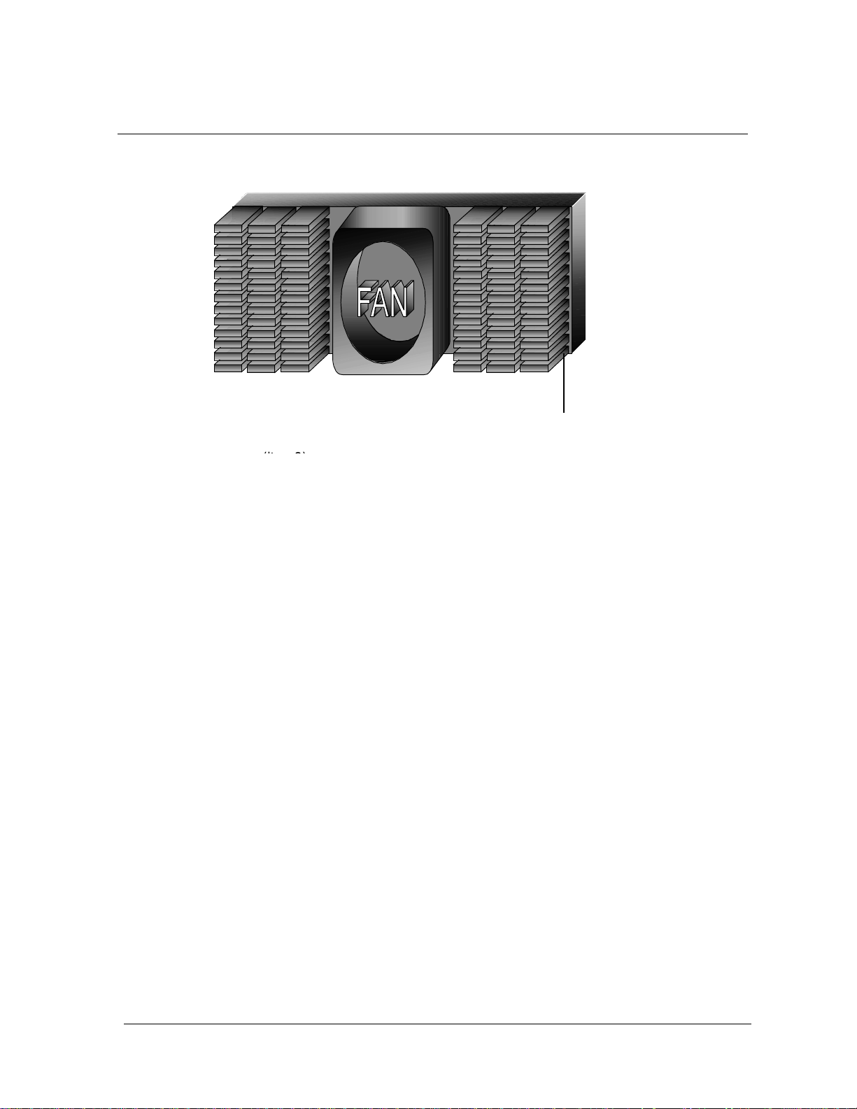
Pentium II Processor Heat Sink
Heat Sink bottom groove for the
Support Top Bar (item8)
Page 6 E6BX-ATX M/B
Manual
Page 8
JUMPER SETTING
C P U
2.6 Installing the Pentium II Processor
1. Mount the Pentium II Retention Module: Place the Retention Module
over the SEC Slot with the Retainer’s Lock Holes toward the
motherboard’s memory slots and screw the captive Nuts using a flat
head screw driver.
2. Insert the SEC Cartridge : Insert the SEC Cartridge into the Locks
indicated on preceding picture (item3) and make sure that the Heat
Sink is facing the memory slot. Push down slowly while holding the
Retention Module’s sides inward so that the SEC Cartridge does not
push away the two walls of the Retention Module.
3. Secure the Heat Sink: Slide the Heat Sink support Top Bar into the
bottom groove of Heat Sink until it locks into the heat sink support
Base Posts.
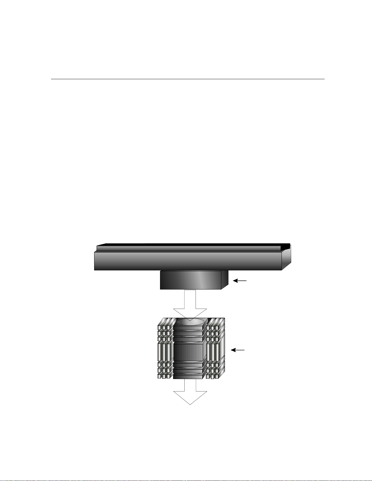
4. Heat Sink Direction For Chipset (440LX): How to allocate Heat Sink on
board efficiently.
CPU FAN
HEAT SINK
________________________________________________________________________________________
E6BX-ATX M/B Manual
Page 7
Page 9
JUMPER SETTING
IDE 1
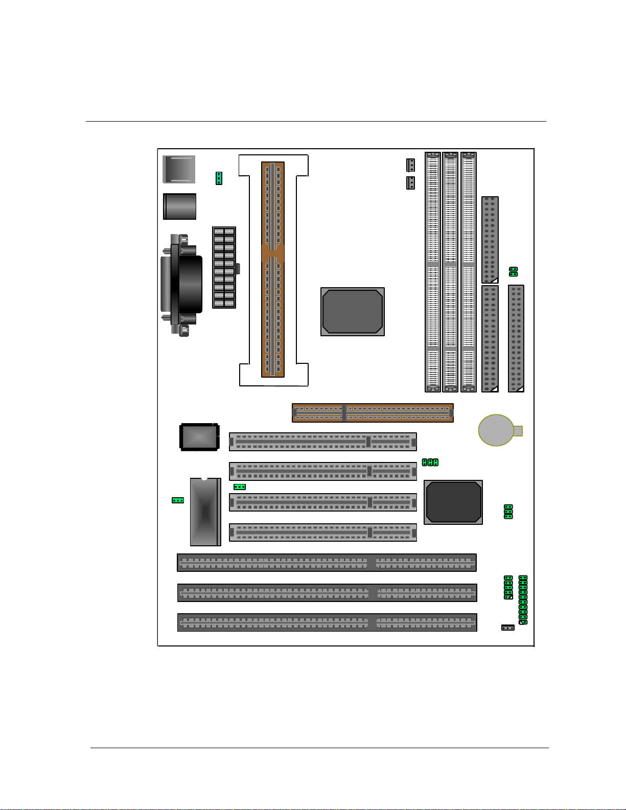
2.7 Chart Of Jumpers
KB/MS1
USB
ATX PWR CONNECTOR
SLOT1
AGP
440BX
POWER FAN
CPU FAN
DIMM1
DIMM2
FDC1
IDE2
DIMM3
W83977
TF
BIOS
PCI4
BAT1
PCI1
PCI2
PCI SET
PCI3
ISA1
ISA2
ISA3
Page 8 E6BX-ATX M/B
Manual
Page 10
3. AWARD BIOS SETUP
3.1 BIOS Setup
The motherboard supports 5V programmable Flash ROM chips. These memory
chips can be updated when BIOS upgrades are released. Use the Flash Memory
Writer utility to download the new BIOS file into the ROM chip as described in detail
in this section.
All computer motherboards provide a Setup utility program for specifying the system
configuration and settings. If your motherboard came in a computer system, the
proper configuration entries may have already been made, If so, enter the Setup
utility, by hitting the Delte key during bootup, and take note of the configuration
settings for future reference; in particular, the hard disk specifications.
If you are installing the motherboard, reconfiguring your system or you receive a
Run Setup message, you will need to enter new setup information. This section
describes how to configure your system using this utility.
The BIOS ROM of the system stores the Setup utility. When you turn on the
computer, the system provides you with the opportunity to run this program. This
appears during the Power-On Self Test (POST). Press the <Delete> Key to call up
the Setup utility. If you are a little bit late pressing the mentioned key(s), POST will
continue with its test routines, thus preventing you from calling up Setup. If you still
need to call Setup, reset the system by simultaneously pressing the <Ctrl>,<Alt>
and <Delete> keys, or by pushing the Reset button on the system case. You can
also restart by turning the system off and then back on again.
AWARD BIOS SETUP
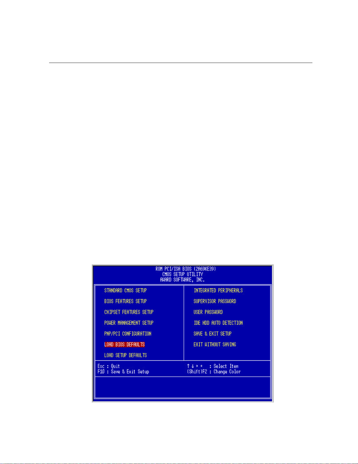
When you enter CMOS Setup, the CMOS SETUP UTILITY main program screen
will appear with the following options:
________________________________________________________________________________________
E6BX-ATX M/B Manual
Page 9
Page 11
AWARD BIOS SETUP
Load Defaults
The “Load BIOS Defaults” option loads the minimized settings for troubleshooting.
“Load Setup Defaults”, on the other hand, is for loading optimized defaults for
regular use, Choosing defaults at this level, will modify all applicable settings.
A section at the bottom of the above screen displays the control keys for this screen.
Take note of these keys and their respective uses. Another section just below the
control keys section displays information on the currently highlighted item in the list.
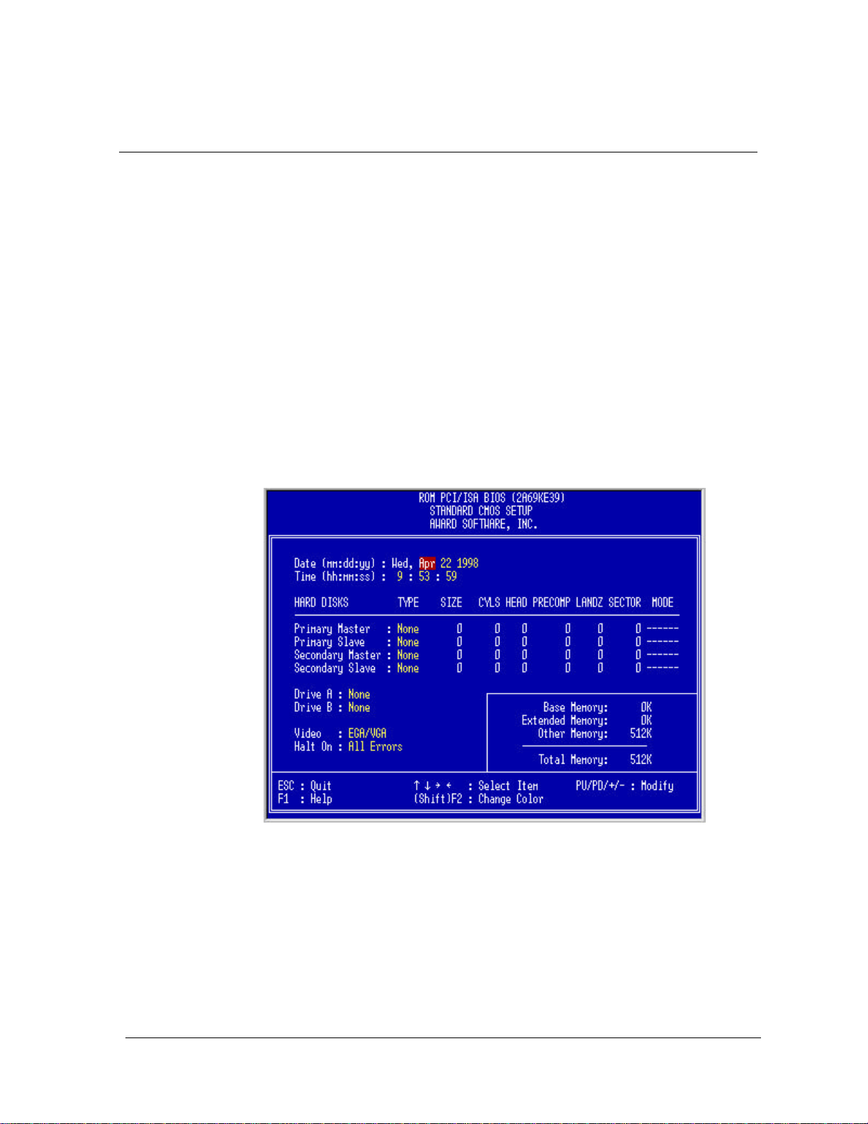
3.2 Standard CMOS Setup
This “Standard CMOS Setup” option allows you to record some basic system
hardware configuration and set the system clock and error handling. If the
motherboard is already installed in a working system, you will not need to select this
option anymore. However, if the configuration stored in the CMOS memory on the
board gets lost or damaged, or if you change your system hardware configuration,
you will need to reenter the configuration values. The configuration values usually
get lost or corrupted when the power of the onboard CMOS battery weakens.
The above screen provides you with a list of options. At the bottom of this screen
are the control keys for use on this screen. Take note of these keys and their
respective uses.
User-configurable fields appear in a different color. If you need information on the
selected field, press the <F1> key. The help menu will then appear to provide you
with the information you need. The memory display at the lower right-hand side of
the screen is read-only and automatically adjusts accordingly.
Page 10 E6BX-ATX M/B
Manual
Page 12

AWARD BIOS SETUP
Date
To set the date, highlight the “Date” field and then press the page up/page down or
+/- keys to set the current date. Follow the month, day and year format. Valid values
for month, day and year are:
Month: 1 to 12
Day: 1 to 31
Year: up to 2099
Time
To set the time, highlight the “Time” field and then press the page up/page down or
+/- keys to set the current time. Follow the hour, minute and second format. Valid
values for hour, minute and second are:
Hour: 00 to 23
Minute: 00 to 59
Second: 00 to 59
You can bypass the date and time prompts by creating an AUTOEXEC.BAT file. For
information on how to create this file, please refer to the MS-DOS manual.
Hard Disk Drives
This field records the specifications for all non-SCSI hard disk drives installed in
your system. The onboard PCI IDE connectors provide Primary and Secondary
channels for connecting up to four IDE hard disks or other IDE devices. Each
channel can support up to two hard disks; the first of which is the “master” and the
second is the “slave”.
Specifications for SCSI hard disks need not be entered here since they operate
using device drivers and are not supported by any of the BIOS. If you install other
vendor’s SCSI controller card, please refer to their respective documentation’s on
how to install the required SCSI drivers.
To enter specifications for a hard disk drive, you must select first a “type”. You can
select “User” and specify the specifications yourself manually, or you can select
from the provided predefined drive specifications. To select, simply press the <Page
Up> or <Page Down> key to change the option listed after the drive letter.
For IDE hard disk drive setup, you can:
• Use the Auto setting for detection during bootup.
• Use the IDE HDD AUTO DETECTION in the main menu to automatically enter
the drive specifications.
• Enter the specifications yourself manually by using the “User” option.
The entries for specifying the hard disk type include CYLS (number of cylinders),
HEAD (number of read/write heads),PRECOMP (write precompensation), LANDZ
(landing zone), SECTOR (number of sectors) and MODE. The SIZE field
automatically adjusts according to the configuration you specify, The documentation
that comes with your hard disk should provide you with the information regarding the
drive specifications.
________________________________________________________________________________________
E6BX-ATX M/B Manual
Page 11
Page 13

AWARD BIOS SETUP
The MODE entry is for IDE hard disks only, and can be ignored for MFM and ESDI
drives. This entry provides three options: Normal, Large, LBA, or Auto (see below).
Set MODE to the Normal for IDE hard disk drives smaller than 528MB; set it to LBA
for drives over 528MB that support Logical Block Addressing (LBA) to allow larger
IDE hard disks; set it to Large for drives over 528MB that do not support LBA. Large
type of drive can only be used with MS-DOS and is very uncommon. Most IDE
drives over 528MB support the LBA mode.
Auto detection of hard disks on bootup
For each field: Primary Master, Primary Slave, Secondary Master, and Secondary
Slave, you can select Auto under the TYPE and MODE fields. This will enable auto
detection of your IDE drives during bootup. This will allow you to change your hard
drives (with the power off) and then power on without having to reconfigure your
hard drive type. If you use older hard drives which do not support this feature, then
you must configure the hard drive in the standard method as described above by the
“User” option.
NOTE: After the IDE hard disk drive information has been entered into BIOS, new
IDE hard disk drives must be partitioned (such as with FDISK) and then formatted
before data can be read from and write on. Primary IDE hard disk drives must have
its partition set to active (also possible with FDISK).
NOTE: SETUP Defaults are noted in parenthesis next to each function heading.
Drive A/Drive B (None)
These fields record the types of floppy disk installed in your system. The available
options for drives A and B are: 360KB, 5.25in.; 1.2MB, 5.25in,; 720KB, 3.5in,;
1.44MB, 3.5in,;None.
To enter the configuration value for a particular drive, highlight its corresponding
field and then select the drive type using the left-or right-arrow key.
Floppy 3 Mode Support (Disabled)
This is the Japanese standard floppy drive. The standard stores 1.2MB in a 3.5”
diskette. This is normally disabled but you may choose from either: Drive A, Drive B,
Both, and Disabled.
Video (EGA/VGA)
Set this field to the type of video display card installed in your system. The options
are: EGA/VGA, Mono (for Hercules or MDA), CGA 40, and CGA 80.
If you are using a VGA or any higher resolution card, choose the “EGA/VGA” option.
Halt On (All Errors)
This field determines which types of errors will cause the system to halt. Choose
from: “All Errors”,” No Errors”,” All, But Keyboard”,” All, But Diskette”, and” All, But
Disk/Key”.
Page 12 E6BX-ATX M/B
Manual
Page 14
3.3 BIOS Features Setup
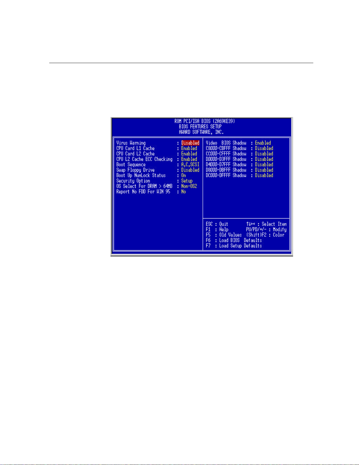
This “BIOS Features Setup “ option consists of configuration entries that allow you
to improve your system performance, or let you set up some system features
according to your preference. Some entries here are required by the motherboard’s
design to remain in their default settings.
AWARD BIOS SETUP
A section at the lower right of the screen displays the control keys you can use. Take
note of these keys and their respective uses. If you need information on a particular
entry, highlight it and then press the <F1> key. A pop-up help menu will appear to
provide you with the information you need. To load the last set values, press the
<F5> key. <F6> and <F7> load the BIOS default values and Setup default values,
respectively.
NOTE: SETUP Defaults are noted in parenthesis next to each function heading.
Virus Warning (Disabled)
This field protects the boot sector and partition table of your hard disk against
accidental modifications. Any attempt to write to them will cause the system to halt
and display a warning message. If this occurs, you can either allow the operation to
continue or use a bootable virus-free floppy disk to reboot and investigate your
system. This setting is recommended because conflicts with new operating systems.
Installation of new operating systems require that you disable this to prevent write
errors.
________________________________________________________________________________________
E6BX-ATX M/B Manual
Page 13
Page 15

AWARD BIOS SETUP
CPU Card L1 Cache (Enabled)
This fields allow you to choose from the default of Enable or choose Disable to turn
on or off the CPU’s Level 1 built-in cache.
CPU Card L2 Cache (Enabled)
This fields allow you to choose from the default of Enable or choose Disable to turn
on or off the CPU’s Level2 built-in cache.
Boot Sequence (A,C,SCSI)
This field determines where the system looks first for an operating system. Options
are A, C, SCSI ; C, A, SCSI ; C, CDROM, A ; CDROM, C, A ; D, A, SCSI ; E, A,
SCSI ; F, A, SCSI ; SCSI, A, C ; SCSI, C, A ; C only; LS/ZIP,C The setup default
setting is to check first the hard disk and then the floppy drive; that is A,C,SCSI.
Swap Floppy Drive (Disabled)
When enabled, the BIOS swaps floppy drive assignments so that Drive A becomes
Drive B, and Drive B becomes Drive A under DOS.
Boot Up NumLock Status (On)
This field enables users to activate the NumberLock function upon system boot.
Security Option (Setup)
This field determines when the system prompts for the password. The default setting
is System, where the system prompts for the User Password every time you boot
up. The other option is Setup, where the system always boots up, and prompts for
the Supervisor Password only when the Setup utility is called up. You can specify a
password by using the Supervisor Password or User Password option from the main
screen as explained later in this section.
OS/2 Select For DRAM > 64M (Non-OS2)
When using OS/2 operating systems with installed DRAM of greater than 64MB, you
need to Enable this option otherwise leave this on the setup default of Non-OS2.
Page 14 E6BX-ATX M/B
Manual
Page 16
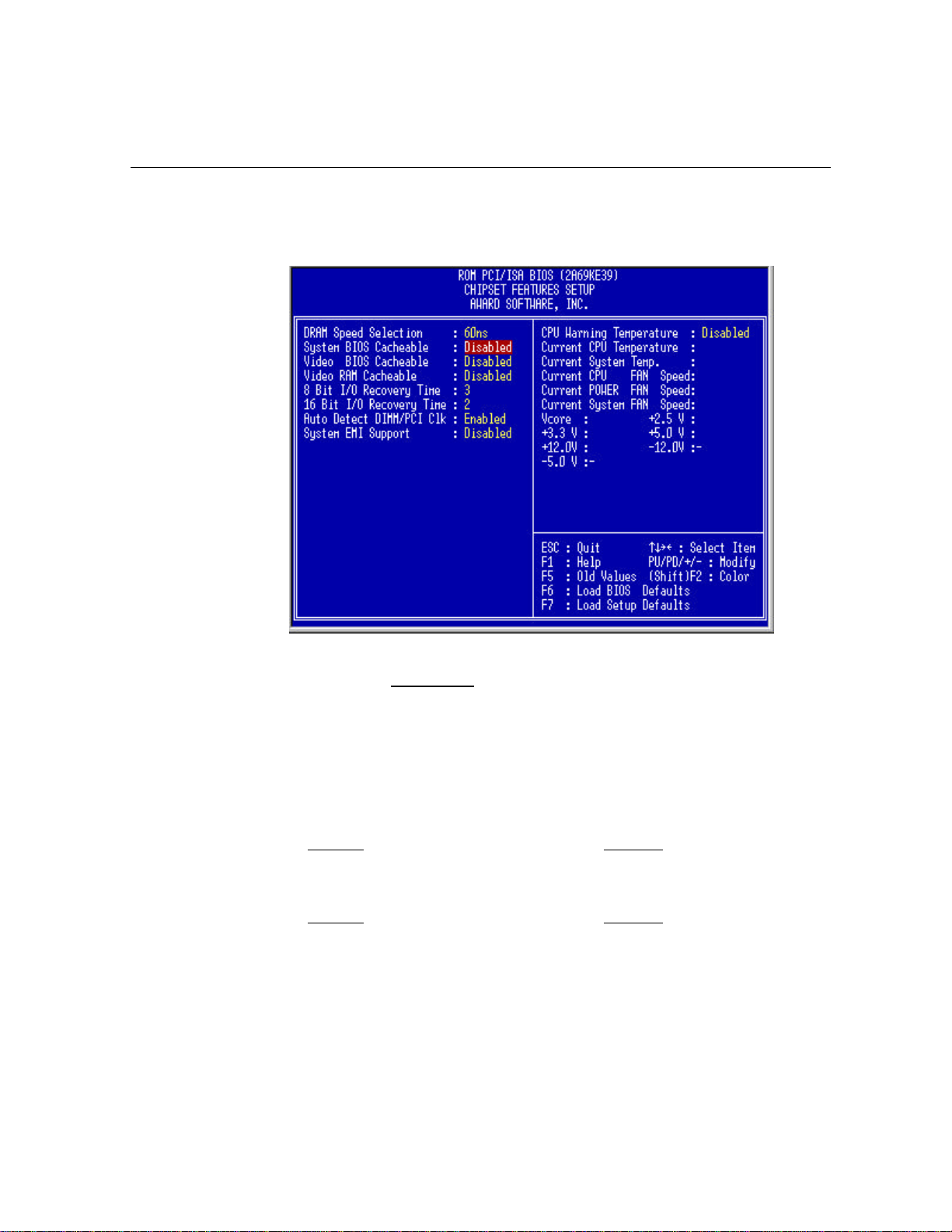
3.4 Chipset Features Setup
This “Chipset Features Setup” option controls the configuration of the board’s
chipset. Control keys for this screen are the same as for the previous screen.
AWARD BIOS SETUP
DRAM Speed Selection (60ns DRAM)
The default setting of 60ns DRAM sets the optimal timings for 60ns DRAM modules.
If you are using 50ns DRAM modules, you must change this item to 50ns DRAM.
System BIOS Cacheable (Disabled)
Enabling this item allows you to cache the system BIOS to further enhance system
performance.
Video BIOS Cacheable (Disabled)
Allows the Video BIOS to be cached to allow faster execution. Leave on default
setting of Enabled for better performance, otherwise Disabled.
Video RAM Cacheable (Disabled)
Allows the Video RAM to be cached to allow faster execution. Leave on default
setting of Enabled for better performance, otherwise Disabled.
8-bit I/O Recovery Time (3 BUSCLK)
This option specifies the ISA back to back cycle. Some ISA CARDS need long
Recovery Time.
________________________________________________________________________________________
E6BX-ATX M/B Manual
Page 15
Page 17

AWARD BIOS SETUP
16-bit I/O Recovery Time (2 BUSCLK)
This option specifies the ISA back to back cycle. Some ISA CARDS need long
Recovery Time.
Auto Detect DIMM/PCI CLK (Enabled)
When this item is set to Enabled, the motherboard will Auto Detect DIMM and PCI
CLK.
System EMI Support (Disabled)
When this item is set to enabled, the motherboard will passed the EMI Test.
CPU Warning Temperature (Disabled)
Enabling this item allows system to slow down when CPU temperature is over
warning temperature.
Current CPU/System Temperature
The onboard hardware monitor is able to detect the CPU and the system
temperatures.
Fan Monitor
The onboard hardware monitor is able to detect the CPU Fan Speed, Power Fan
Speed, and System Fan Speed in Rotations Per Minute (RPM). These values
refresh upon any key entries in the BIOS setup screen.
Voltage Monitor
The onboard voltage monitor is able to detect the voltages put out by the voltage
regulators. These values refresh upon key entries.
Page 16 E6BX-ATX M/B
Manual
Page 18
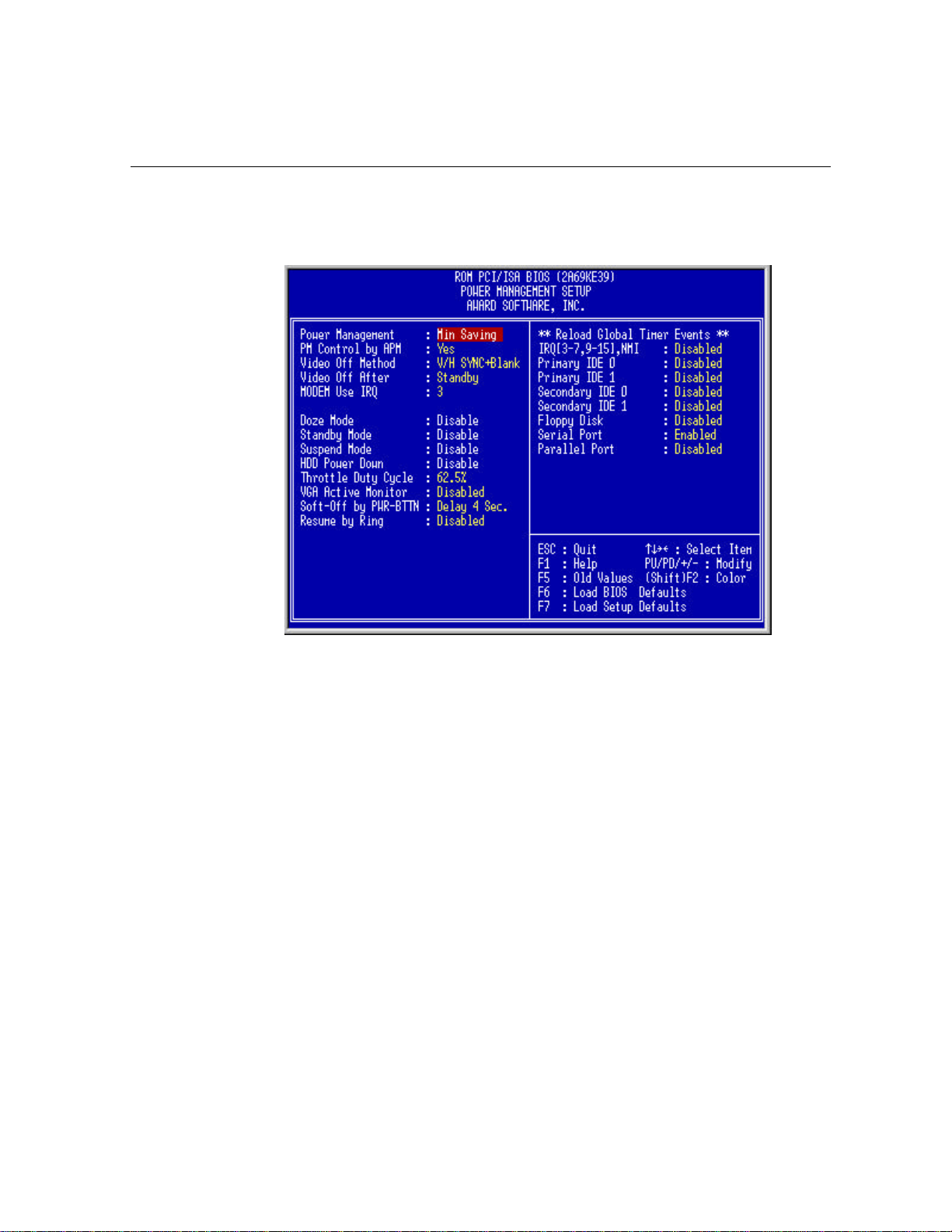
3.5 Power Management Setup
The Power Management Setup screen enables you to control the mainboard green
features. See the following screen.
AWARD BIOS SETUP
Power Management (Min Saving)
This function allows you to set the default parameters of power-saving modes. Set
to Disable to turn off power management function. Set to Use Defined to choose
your own parameters.
PM Controlled by APM (Yes)
If “Max Saving” is selected, you can turn on this item, transfer power management
control to APM (Advanced Power Management) and enhance power saving
function. For example, stop CPU internal clock.
Video Off Method (V/H SYNC + Blank)
This determines the way that monitor is off. Blank Screen writes blanks to video
buffer. V/H SYNC + Blank allows BIOS to control VSYNC and HSYNC signals. This
function applies only for DPMS (Display Power Management Standard ) monitor.
The DPMS mode uses DPMS function provided by VGA the card.
Video Off After (Standby)
To turn off video monitor at which power down mode.
________________________________________________________________________________________
E6BX-ATX M/B Manual
Page 17
Page 19

AWARD BIOS SETUP
MODEM Use IRQ (3)
You can set IRQs 3, 4, 5, 7 individually through modem. Activity detected from any
IRQ channel will wake up the system.
Doze Mode (Disabled)
This item lets you set the period of time after which the system enters into Doze
mode. In this mode, the CPU clock slows down. The ratio is specified in the “Throttle
Duty Cycle”. Any activity detected returns the system to full power. The system
activity (or event) is detected by monitoring the IRQ signals.
Standby Mode (Disabled)
This item lets you set the period of time after which the system enters into Standby
mode. In this mode, CPU clock slows down, hard disk will be shut off and the
monitor power-saving feature activates. Any activity detected returns the system to
full power. The system activity (or event) is detected by monitoring the IRQ signals.
Suspend Mode (Disabled)
This item lets you set the period of time after which the system enters into Suspend
mode. The Suspend mode can be Power On Suspend or Suspend to Hard Drive,
selected by “Suspend Mode Option”.
HDD Power Down (Disabled)
This option lets you specify the IDE HDD idle time before the device enters the
power down state. This item is independent from the power states previously
described in this section (Standby and Suspend).
Throttle Duty Cycle (62.5%)
Clock Throttling means at the Doze/Standby state. The CPU clock count in a given
time (not the frequency) is reduced to the ratio specified in the parameter. Actually,
the period per CPU clock remains the same 30ns clock period when system goes
into Doze/Suspend. The chipset generates the STPCLK (stop clock) signal
periodically to prevent CPU for accepting clock from clock generator. For full power
on, the CPU can receive 66M count in one second. If the Slow Clock Ratio is set to
50%, the CPU will only receive 33M clock count in one second. This will effectively
reduce CPU speed as well as CPU power.
VGA Active Monitor (Disabled)
To enable or disable the detection of VGA activity for power down state transition.
Soft-Off by PWR-BTTN (Delay 4 Sec)
The system can be in one of two states, one is suspend mode and the other is the
Soft-Off mode. Pushing the power button for less than 4 seconds places the system
into suspend mode. When the power button is pressed for more than 4 seconds, it
enters the Soft-Off mode.
Page 18 E6BX-ATX M/B
Manual
Page 20

AWARD BIOS SETUP
Resume by Ring (Disabled)
Enabled this item allows computer to be turned on remotely through a modem.
IRQ[3-7, 9-15]
To enable or disable the detection of IRQ3-7, IRQ9-15 or NMI interrupt events for
power down state transition.
Primary IDE 0
Primary IDE 1
Secondary IDE 0
Secondary IDE 1
Floppy Disk
Serial Port
Parallel Port
These items enable or disable the detection of IDE, floppy, serial and parallel port
activities for power down state transition. Actually it detects the read/write to/from
I/O or address port.
________________________________________________________________________________________
E6BX-ATX M/B Manual
Page 19
Page 21
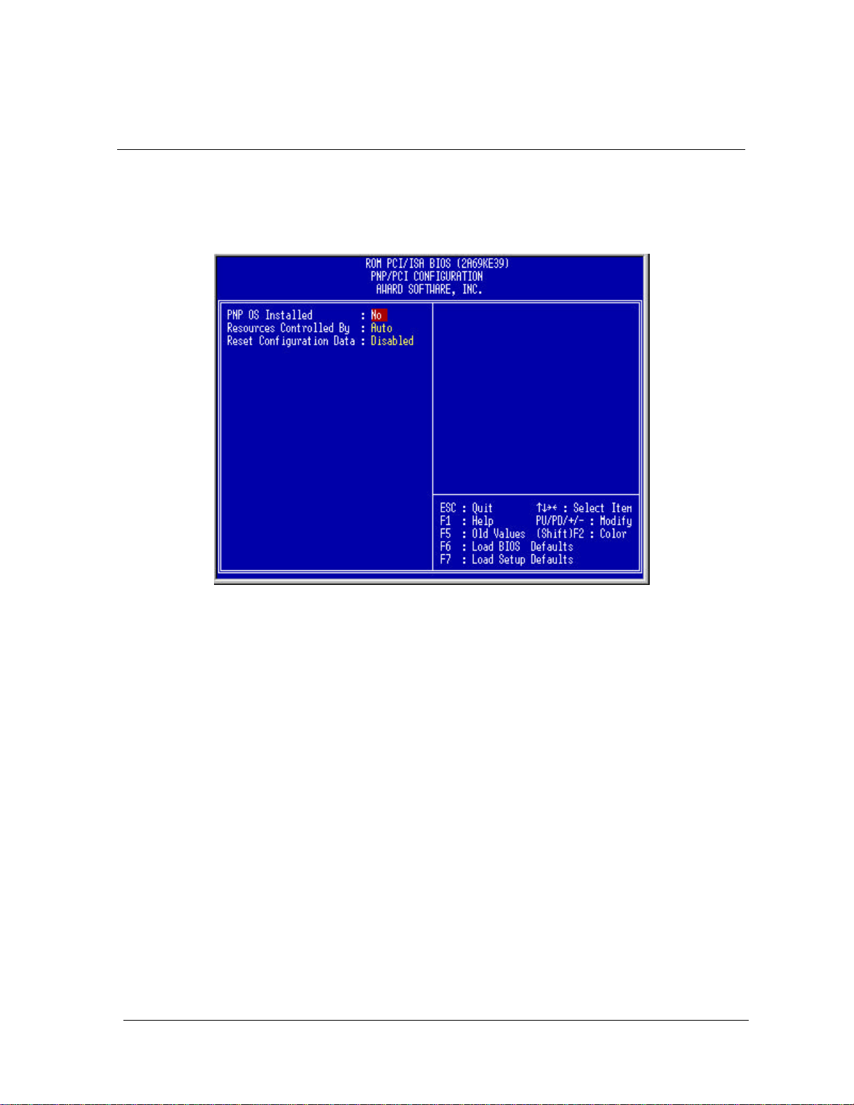
AWARD BIOS SETUP
3.6 PNP/PCI Configuration Setup
The PNP/PCI Configuration Setup allows you to configure the ISA and PCI devices
installed in your system. The following screen appears if you select the option
“PNP/PCI Configuration Setup “from the main menu.
PnP OS Installed (No)
Normally, the PnP resources are allocated by BIOS during POST (Power-On Self
Test). If you are using a PnP operating system (such as Windows 95), set this item
to Yes to inform BIOS to configure only the resources needed for booting (VGA/IDE
or SCSI). The rest of system resources will be allocated by PnP operating system.
Resources Controlled By (Auto)
Setting this option to Manual allows you to individually assign the IRQs and DMAs to
the ISA and PCI devices. Set this to Auto to enable the auto- configuration function.
Reset Configuration Data (Disabled)
In case conflict occurs after you assign the IRQs or after you configure your system,
you can enable this function, allow your system to automatically reset your
configuration and reassign the IRQs.
Page 20 E6BX-ATX M/B
Manual
Page 22
3.7 Load BIOS Defaults
This “Load BIOS Defaults” option allows you to load the troubleshooting default
values permanently stored in the BIOS ROM. These default settings are non-optimal
and disable all high performance features. To load these default settings, highlight
“Load BIOS Defaults” on the main screen and then press the <Enter> key. The
system displays a confirmation message on the screen. Press the<Y> key and then
the <Enter> key to confirm. Press the <N> key and then the <Enter> key to abort.
This feature does not affect the fields on the Standard CMOS Setup screen.
3.8 Load Setup Defaults
This “Load Setup Defaults” option allows you to load the default values to the
system configuration fields. These default values are the optimized configuration
settings for the system. To load these default values, highlight “Load Setup
Defaults” on the main screen and then press the <Enter> key. The system displays a
confirmation message on the screen. Press the <Y> key and then the <Enter> key
to confirm. Press the <N> key and then the <Enter> key to abort. This feature does
not affect the fields on the Standard CMOS Setup screen.
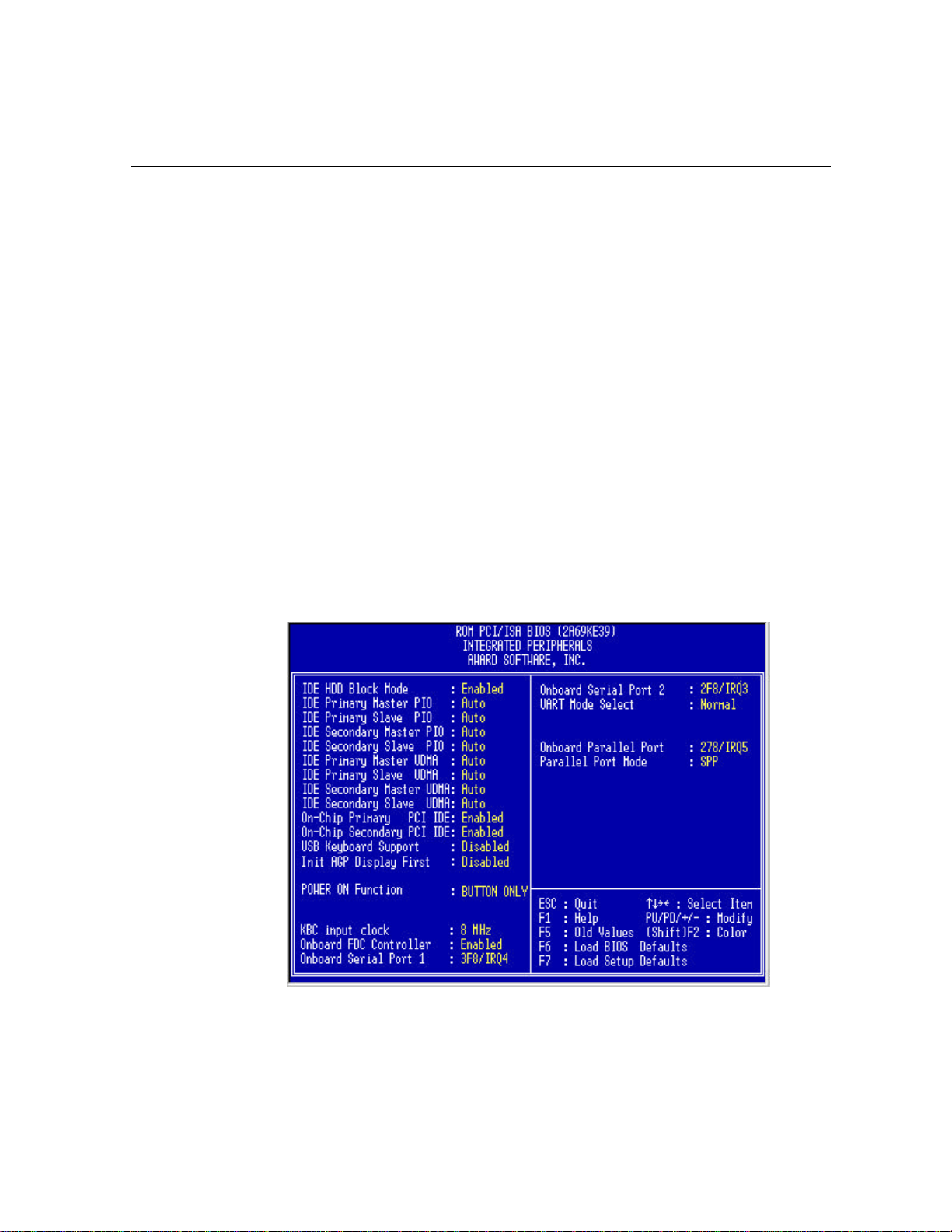
3.9 Integrated Peripherals
The following screen appears if you select the option “Integrated Peripherals” from
the main menu. This option allows you to configure the I/O features.
AWARD BIOS SETUP
________________________________________________________________________________________
E6BX-ATX M/B Manual
Page 21
Page 23

AWARD BIOS SETUP
On-Chip Primary PCI IDE (Disabled)
On-Chip Secondary PCI IDE (Disabled)
These parameters lets you enable or disable the IDE device connected to the
primary/secondary IDE connector.
IDE Primary Master PIO (Auto)
IDE Primary Slave PIO (Auto)
IDE Secondary Master PIO (Auto)
IDE Secondary Slave PIO (Auto)
Setting these items to Auto activates the HDD speed auto-detect function. The PIO
mode specifies the data transfer rate of HDD. For example: mode 0 data transfer
rate is 3.3MB/s, mode 1 is 5.2MB/s, mode 2 is 8.3MB/s, mode 3 is 11.1MB/s and
mode 4 is 16.6MB/s. If your hard disk performance becomes unstable, you may
manually try the slower mode.
IDE Primary Master UDMA (Auto)
IDE Primary Slave UDMA (Auto)
IDE Secondary Master UDMA (Auto)
IDE Secondary Slave UDMA (Auto)
These items allows you to set the Ultra DMA/33 mode supported by the hard disk
drive connected to your primary/secondary IDE connector.
Power ON Function (BUTTON ONLY)
You can select one of “button only , password , Hot-Key , Mouse-Left , or MouseRight” switch to power on.(Note : Mouse is for PS/2 mouse)
USB Keyboard Support (Disabled)
This item lets you enable or disable the USB keyboard driver within the onboard
BIOS. The keyboard driver simulates legacy keyboard command and let you use
USB keyboard during POST or after boot if you don’t have USB driver in the
operating system.
Onboard FDC Controller (Enabled)
Setting this parameter to Enabled allows you to connect your floppy disk drives to
the onboard floppy disk connector instead of a separate controller card. Change the
setting to Disabled if you want to use a separate controller card.
Onboard Serial Port 1 (3F8/IRQ4)
This option specifies the first serial port address and IRQ on the motherboard.
Onboard Serial Port 2 (2F8/IRQ3)
This option specifies the secondary serial port address and IRQ on the motherboard.
UART Mode Select (Normal)
This option specifies the COM port operation mode as Standard, HPSIR or ASKIR.
Page 22 E6BX-ATX M/B
Manual
Page 24

AWARD BIOS SETUP
Onboard Parallel Port (378/IRQ7)
This item controls the onboard printer port address and interrupt.
Parallel Port Mode (SPP)
This item lets you set the parallel port mode. The mode options are Normal
(Standard and Bidirection Printer Port), EPP (Enhanced Printer Port) and
ECP(Extended Printer Port). Normal is the IBM AT and PS/2 compatible mode. EPP
enhances the printer port throughput by directly writing/reading data to/from printer
port without latch. ECP supports DMA and RLE (Run Length Encoded) compression
and decompression.
3.10 Supervisor Password and User Password
These two options set the system passwords. “Supervisor Password” sets a
password that will be used to protect the system and the Setup utility; “User
Password” sets a password that will be used exclusively on the system. By default,
the system comes without any passwords. To specify a password, highlight the type
you want and then press the <Enter> key. A password prompt appears on the
screen. Taking note that the password is case sensitive, and can be up to 8
alphanumeric characters long, type in your password and then press the <Enter>
key. The system confirms your password by asking you to type it again. After setting
a password, the screen automatically reverts to the main screen. To implement the
password protection, specify in the “Security Option” field of the BIOS Features
Setup screen when the system will prompt for the password. If you want to disable
either password, press the <Enter> key instead of entering a new password when
the “Enter Password” prompt appears. A message confirms the password has been
disabled.
3.11 IDE HDD AUTO Detection
This “IDE HDD Auto Detection” option detects the parameters of an IDE hard disk
drive, and automatically enters them into the Standard CMOS Setup screen.
ROM PCI/ISA BIOS (2A59IE39)
CMOS SETUP UTILITY
AWARD SOFTWARE, INC.
HARD DISKS TYPE SIZE CYLS HEAD PRECOMP LANDZ SECTOR MODE
Primary Master :
Select Primary Master Option (N=Skip) : N
OPTION
SIZE
CYLS
HEADS
PRECOMP
1 (Y)
516
1120
2
516
3
516
Note : Some OSes (like SCO-UNIX) must use "NORMAL" for installation
16
524
32
560
32
65535
65535
LANDZONE
0
1119
1119
1119
SECTORS
59
63
59
MODE
NORMAL
LBA
LARGE
________________________________________________________________________________________
E6BX-ATX M/B Manual
Page 23
Page 25

AWARD BIOS SETUP
Up to four IDE drives can be detected, with parameters for each listed inside the
box. To accept the optimal entries, press the <Y> key or else select from the
numbers displayed under the OPTIONS field (2,1,3 in this case); to skip to the next
drive, press the <N> key. If you accept the values, the parameters will appear listed
beside the drive letter on the screen. The process then proceeds to the next drive
letter. Pressing the <N> key to skip rather than to accept a set of parameters causes
the program to enter zeros after that drive letter.
Remember that if you are using another IDE controller that does not feature
Enhanced IDE support for four devices, you can only install two IDE hard disk
drives. Your IDE controller must support the Enhanced IDE features in order to use
Drive E and Drive F. The onboard PCI IDE controller supports Enhanced IDE, with
two connectors for connecting up to four IDE devices. If you want to use another
controller that supports four drives, you must disable the onboard IDE controller in
the Chipset Features Setup screen.
When auto-detection is completed, the program automatically enters all entries you
accepted on the field for that drive in the Standard CMOS Setup screen. Skipped
entries are ignored and are not entered in the screen.
If you are auto-detecting a hard disk that supports the LBA mode, three lines will
appear in the parameter box. Choose the line that lists LBA for an LBA drive. Do not
select Large or Normal.
The auto-detection feature can only detect one set of parameters for a particular
IDE hard drive. Some IDE drives can use more than one set. This is not a problem if
the drive is new and there is nothing on it.
IMPORTANT: If your hard drive was already formatted on an older previous system,
incorrect parameters may be detected. You will need to enter the correct parameters
manually or use low-level format if you do not need the data stored on the hard
drive.
If the parameters listed differ from the ones used when the drive was formatted, the
drive will not be readable. If the auto-detected parameters do not match the ones
that should be used for your drive, do not accept them. Press the <N> key to reject
the presented settings and enter the correct ones manually from the Standard
CMOS Setup screen.
3.12 Save and Exit Setup
Select this option to save into the CMOS memory all modifications you specify
during the current session. To save the configuration changes, highlight the “Save &
Exit Setup” option on the main screen and then press the <Enter> key.
3.13 Exit Without Saving
Select this option to exit the Setup utility without saving the modifications you
specify during the current session. To exit without saving, highlight the “Exit Without
Saving” option on the main screen and then press the <Enter> key.
Page 24 E6BX-ATX M/B
Manual
 Loading...