

EEZ RV EezTire T515 Instruction Manual

EEZ RV PRODUCTS
EezTire T515 SYSTEM
WIRELESS TIRE PRESSURE AND
TEMPERATURE MONITORING SYSTEM (TPMS)
Instruction Manual
Model No: TM-515T22/SP

TABLE OF CONTENTS
SYSTEM COMPONENTS - ANTI-THEFT SENSORS ........................................ 4
SYSTEM COMPONENTS - FLOW - THROUGH SENSORS ............................. 4
MONITOR COMPONENTS & ICONS .............................................................. 5
TPMS MAIN FEATURES .................................................................................... 5
Reduce Driving Risks .......................................................................................................................... 5
Improve Fuel Economy ..................................................................................................................... 5
Prolong Lifetime of Tires ................................................................................................................... 5
SYSTEM OVERVIEW ......................................................................................... 6
GENERAL INFORMATION ................................................................................ 6
PRODUCT FEATURES ....................................................................................... 7
Monitor Features ................................................................................................................................. 7
Sensor Features .................................................................................................................................... 8
Transceiver Features (optional part) ............................................................................................. 8
STEP BY STEP SET UP INSTRUCTIONS .......................................................... 8
SETTING YOUR SYSTEMS ALARM PARAMETERS ........................................ 9
Settings Sequence:
Choosing A Pressure Unit of Measure .......................................................................................... 9
Choosing A Temperature Unit of Measure ................................................................................. 9
High Pressure Parameter Front Axle .......................................................................................... 10
Low Pressure Parameter Front Axle ........................................................................................... 10
High Pressure Parameter 2nd Axle ............................................................................................ 11
Low Pressure Parameter 2nd Axle .............................................................................................. 11
High Pressure Parameter 3rd Axle .............................................................................................. 11
Low Pressure Parameter 3rd Axle ............................................................................................... 11
High Pressure ParameterTow Vehicle ........................................................................................ 12
Low Pressure Parameter Tow Vehicle ........................................................................................ 12
High Temperature Parameter ....................................................................................................... 12
PROGRAMMING SENSORS TO THE MONITOR .......................................... 13
Programming Sensors (Method 1 - Air Pressure Activation) ............................................. 13
Programming Sensors (Method 2 - O the Vehicle: Flow-Through/T508) ................... 14
Programming Sensors (Method 3 - On the Vehicle: Flow-Through/T508) ................... 15
Monitor Display in Operating Mode ........................................................................................... 16
MONITOR INSTALLATION ............................................................................................. 17
SENSOR INSTALLATION ................................................................................................. 19
DELETING SENSOR CODES FROM THE MONITOR .................................... 20
Delete a Single Sensor Code ................................................................................................................. 20
Deleting all Sensors Codes .................................................................................................................... 20
OTHER FUNCTIONS ...................................................................................... 20
Normal Scrolling Display ................................................................................................................ 20
Backlighting ........................................................................................................................................ 20
Connecting/Disconnecting the Trailor ..................................................................................... 20
Charging the Monitor ...................................................................................................................... 21
Viewing ID Code ................................................................................................................................ 21
OUT OF PARAMETER ALERTS ........................................................................ 21
Monitor Alerts:
High Pressure Alert ........................................................................................................................... 21
Low Pressure Alert ............................................................................................................................ 21
2
High Temperature Alert .................................................................................................................. 22
Fast Leakage Alert ............................................................................................................................. 22
Sensor Low Battery Alert ................................................................................................................ 22
REPLACING THE SENSOR BATTERY - ANTI-THEFT SENSORS .................. 23
REPLACING THE SENSOR BATTERY - FLOW-THROUGH SENSORS ......... 24
REPEATER/SIGNAL BOOSTER (OPTIONAL PART - RP02-06) ................... 25
Recreational Vehicles, Tow Vehicles & Trailers
Placement Instructions ........................................................................................................................... 25
Installation Instructions .......................................................................................................................... 25
Repeater Specications .......................................................................................................................... 26
REPEATER/SIGNAL BOOSTER INSTALLATION & PROGRAMMING (OPTIONAL PART)
26
Big Rig & Owners of Multiple Trailers or Tow Vehicles
How to Operate .................................................................................................................................. 27
Entering Tractor & Trailor ID for the First Time .......................................................................
Monitor Sending Data to Repeater/Booster for the First Time ........................................
Repeater/Booster Sending Data to Monitor (For Trailor Exchange) ................................28
27
27
REPEATER/BOOSTER ALERTS .................................................................... 28
High/Low Pressure & Fast Leakage Alerts ................................................................................ 28
High Temperature Alert ...................................................................................................................28
SPECIFICATIONS ............................................................................................. 29
Monitor.................................................................................................................................................. 29
Sensors - Anti-Theft .......................................................................................................................... 29
Sensors - Flow Through .................................................................................................................. 29
Transceiver (optional parts) ........................................................................................................... 29
TROUBLESHOOTING .............................................................................. 3034
CAUTIONS....................................................................................................... 35
LIMITED WARRANTY & GUARANTEE ........................................................ 35
TIRE SENSOR PLACEMENT DIAGRAM ...................................................... 36
3
3
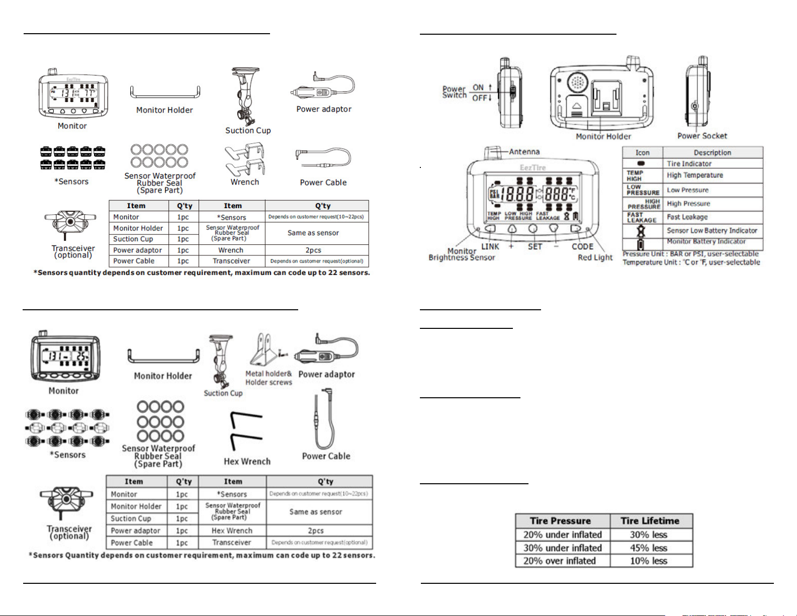
SYSTEM COMPONENTS: ANTITHEFT SENSORS
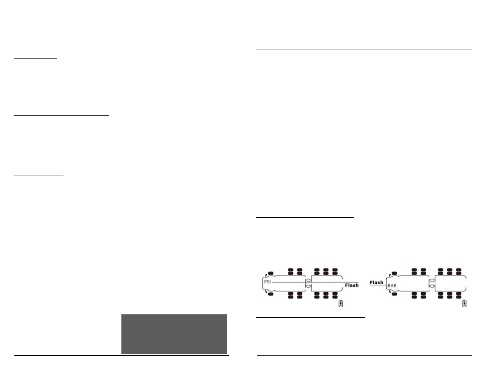
MONITOR COMPONENTS AND ICONS
SYSTEM COMPONENTS: FLOW THROUGH SENSORS
4
TPMS MAIN FEATURES
Reduce Driving Risks
It was reported that an astonishing 75% of all running tires in the USA are
under-inated and 70% of fatal trac accidents were caused by tire blowouts. With a Tire Pressure and Temperature Monitoring System (TPMS),
drivers are warned of abnormal tire conditions before it becomes dangerous.
Improve Fuel Economy
Today’s tire designs make visual inspection of deated tires very dicult.
Very often, a 30% under inated tire looks very much like a fully inated one.
A TPMS will make sure your tire pressure is at its proper level.
A 9 psi drop in tire pressure will cause approximately a 4% increase in fuel
consumption.
Prolong Lifetime of Tires
The following table shows a simple relationship between tire pressure and
tire lifetime:
567

SYSTEM OVERVIEW
This EEZ RV PRODUCTS EezTire T515/SP Tire Pressure and Temperature
Monitoring System (TPMS) is a heavy duty versatile system designed to
operate on a variety of vehicles. (i.e. Motor Coach, 5th Wheel, Travel Trailer,
Auto, Trailer, Big Rig, Farm and Mining Equipment).
The system comes with a monitor that can handle 22 wheels with pressures
up to 210 psi. The sensors are light weight and do not aect the tire balance
and have easy to change replaceable batteries. The system oers a method
of also dropping the towed vehicle and then picking it back up again when
connected.
The monitor scrolls automatically through each wheel measuring tire
pressure and temperature, displaying it on the monitor. Alarms can be
preset by the operator so visible and audible alarms can warn the driver of a
catastrophic failure (rapid air pressure loss), high or low pressures and high
temperature. The alarms and monitoring are sent wirelessly in real time to
the cab allowing the operator to monitor tires that are out of their vision. The
audible alarm eliminates the need to continually watch the monitor.
Tire Pressure can be displayed in PSI or Bar and temperature in Fahrenheit
(F) or Celsius (C). Pressure alerts can be set to a dierent pressure setting for
each axle, so additional towed trailers or vehicles are no problem. The high
ecient sensors can transmit to distances up to 53 feet without a booster
and are easy to install. If needed, an optional booster can be purchased from
your dealer or at www.eezrvproducts.com.
The monitor has its own rechargeable Lithium Ion battery pack and can be
used as a handheld wireless tire pressure gauge when the operator adjusts
the tire pressures. Sensors come with either the anti-theft security feature or
ow-through feature and the monitor comes with both an auxiliary charger
and a hard wire cable at no extra charge.
The EEZ RV PRODUCTS EezTire T515/SP TPMS System oers both easy
installation and one of the largest LCD display monitors on the market.
GENERAL INFORMATION
A tire professional or your owners manual should be used to determine the
proper tire pressure for your vehicle. Recommended operating tire pressures
should be set when the ambient temperature is low or cold.
Dramatic changes in tire pressure can occur because of; increased or
decreased ambient temperature, tire contact surface temperature, wheel and
axle loads, sun shining on a particular side etc. These and other conditions
should be taken into consideration when setting initial tire operating
pressures.
This system cannot warn you of side wall failures; however, it can supply you
with irregular pressures and temperature information that may help to
prevent this. If the monitor is shut o overnight simply switch the monitor
back on prior to departure and your real time tire pressures and
temperatures will be updated and typically appear on the screen within 5
to 10 minutes. Even if the monitor is in the sleep mode the system is always
monitoring and will alarm should any pressure settings or temperatures be
out of your set parameters.
The Schrader Valve (core - inside the valve stem) should be the correct size,
be in good condition and be able to be depressed fully to allow the release
of air to the sensor so it can operate. Some valve stem extensions may cause
inaccurate readings if they do not allow the sensor to operate correctly,
metal bodied stems or T-Valve type are recommended for best performance.
Should you have diculty with a pressure sensor not operating correctly we
recommend that you contact a tire professional to ensure that the tire stem
and Schrader Valve are installed and operating correctly. Do not use tire
sealants or balancing compounds that can enter the sensor body when using
this system. Over a period of time tires may loose pressure naturally, through
the tire itself or for other reasons such as rim leakage etc. However, after
the EezTire TPMS valve sensors (including locking mechanism, if tted) are
installed it is recommended that the sensor and valve stem be completely
covered in a soapy solution of 1 part liquid soap to 2 parts water, to see if
there are any air bubbles coming from the valve and sensor area indicating
that the tire is leaking air. If air bubbles are visualized in any of these areas,
the tire may deate. The wheel sensors are weatherproof and can be run in
the rain.
A tire professional should be consulted should any of these areas prove to be a problem.
Purchasers of this product should not solely rely on this tire pressure
monitoring system for safety and should check the condition and pressure of
their vehicles tires on a regular basis as described by the manufacturer of the
vehicle or tire manufacturer. Please note, the EEZ RV PRODUCTS EezTire T515/
SP TPMS System operates on an RF system, as with many RF tire systems this
system can occasionally suer from interference depending on the systems
location; thus causing the system to be inaccurate or not operate at all. Tire
pressures and temperatures are not the only things that can aect tire safety;
we suggest daily visual inspections and periodic checks by tire professionals.
PRODUCT FEATURES
Monitor Features
• Reliable and easy to install.
• Large 3 1/2 inch LCD screen.
• Built-in rechargeable lithium ion battery.
• Automatic light sensor and backlight.
• Built in motion sensor.
• Congurable high/low pressure warnings.
• Congurable high temperature warnings.
• Visible and audible alerts.
• Selectable pressure units.
• Can monitor in either standard or metric measurements (psi or bar/F or C)
• Monitors up to 22 tires maximum.
• Long range between sensors and monitor.
• Per axle measurements can be congured on the tractor.
Sensor Features
• Reliable cap sensors, easy to install.
• Water resistant.
• Replaceable sensor batteries.
• Fast leakage alert.
• Individually coded sensors.
• Anti-theft or ow-through design.
Transceiver Features (optional part)
• Maintains signal stability.
• Records sensor !D, trailer !D and tire pressure and temperature limits.
• Supports truck and trailer exchange.
• Transferable trailer sensor data between monitor and transceiver.
• Visible and audible alerts.
• Fixed alert for high temperature (194°F)
SYSTEM SETUP
This portion is designed to make the set-up of your new EEZ RV PRODUCTS
EezTire T515/SP TPMS System easier and faster.
Much of the information contained in this manual is found through real life
experience using the system and passed on to hopefully make the use of the
system easier for you.
Please read through the guide completely prior to starting. Complete set-up
should take approximately 20 minutes.
START YOUR SET UP HERE - Step by Step Instructions:
1. Unpack all of the components of your TPMS System and ensure it is
complete.
2. Take the number kit from the accessory pack and number all your
sensors as indicated below.
polish and paint over the number. This will help ensure it stays on in inclement weather conditions.)
3. On the diagram on the last page of this manual assign the numbered
sensors to each tire as they will be put on your rig and tow vehicle.
(Hint: After aff ixing the number to the sensor take some clear nail
4. Program the alarm parameters using STEP 1: SETTING YOUR SYSTEMS
ALARM PARAMETERS
5. Program each sensor to the monitor using STEP 2: PROGRAMMING
SENSORS TO THE MONITOR
STEP 1: SETTING YOUR SYSTEMS ALARM PARAMETERS
(By Sequence)
Refer to the diagram on th e last page of this manual where you w rote the sensor number for each tire.
1. Next to each axle write down what your tire pressure is by axle and calculate
what your alarm setting will be.
2. High Pressure setting will be (20% above axle tire pressure).
3. Low Pressure setting will be (10% below axle tire pressure).
Example: Front Axle Tire Pressure is: 100 psi
High Pressure Alarm Setting will be: 120 psi (100 psi x 1.20 (or 20%) = 120
Low Pressure Alarm Setting will be: 90 psi (100 psi x .9 (or 90%) = 90
These are industry standards for the initial set-up, some adjustment may be
needed after your rst trip. Every brand of tire operates dierently, when
some brands reach operating temperature the psi will increase 5 psi, other
brands may increase 20 - 22 psi. During your rst trip you will see if you need
to increase your High Pressure Alarm setting. For the temperature it is
recommended leaving it at the factory default of 158 degree F.
Choosing A Pressure Unit of Measure
1. Press the SET button and hold it approximately 3 seconds until you hear
the beep. You will rst see PSI or BAR (for metric) in the rst window. Use
the + or – key to scroll between the two. When the one you want to use
appears in the screen press and release the SET button. (Pressing and
releasing the SET button in this mode is like saying yes to what the
screen is showing you)
Choosing a Temperature Unit of Measure
2. It will automatically move to the next window which will show you F
(Fahrenheit) or C (Celsius) for the degree setting in the second window.
Use the + or – key to scroll between the two. When the one you want to
use appears in the screen press the SET button and release.
8
9
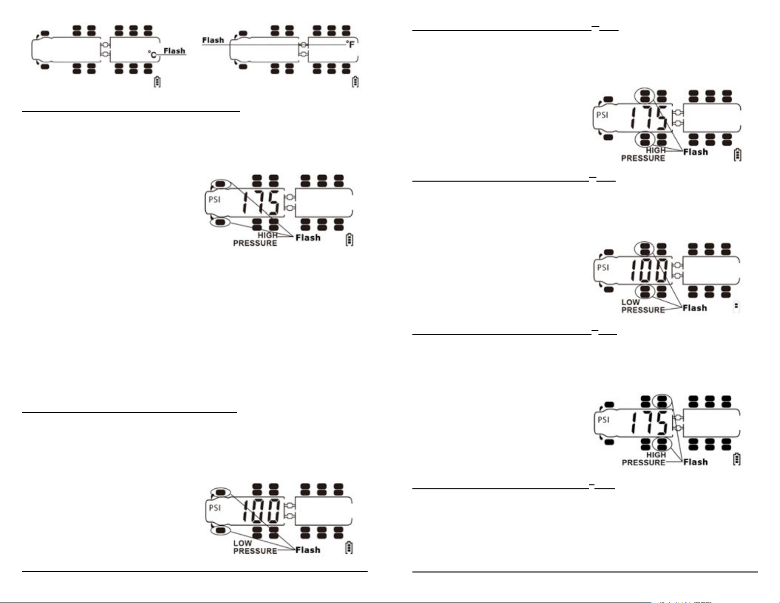
Setting High Pressure Alarm Parameter - Front Axle
3. Now the front axle should be ashing with the words High Pressure on
the bottom of the screen. Press the + or – keys to make the pressure
scroll up and down. Once you reach the High Pressure setting you desire
press the SET button and release.
NOTES:
1. You may notice when you attempt to scroll below 100 psi it will go to 102 psi and then
scrolls back to 210 psi. This is because the system is set up in two modules; 0-102 psi and
102-210 psi. In this case stop at 102 psi and press SET and release to go onto the next set
up. Once you have completed programming the other axles scroll back to those axles that
did not allow you to go below 102 psi. The second time the monitor will recognize you
want the lower module and allow you to scroll below 102 psi.
2. It will go to the next axle to repeat the process. It will show you all the tires and axles
even though they may not be utilized for your set up. If you have no tires on a particular
axle you can simply press and release the SET button to move on. Tires and axles with no
sensors will not show up on your screen when completed.
Setting High Pressure Alarm Parameter - 2
nd
Axle
5. Now the second axle should be ashing with the words High Pressure on
the bottom of the screen. Press the + or – keys to make the pressure
scroll up and down. Once you reach the High Pressure setting you desire
press the SET button and release.
Setting Low Pressure Alarm Parameter - 2
nd
Axle
6. Now your second axle should be ashing with the Low Pressure showing
on the bottom of the screen. Press the + or – keys to make the
pressure scroll up and down. Once you reach the Low Pressure setting
you desire press the SET button and release.
Setting High Pressure Alarm Parameter - 3
rd
Axle
7. Now the third axle should be ashing with the words High Pressure on
the bottom of the screen. Press the + or – keys to make the pressure
scroll up and down. Once you reach the High Pressure setting you desire
press the SET button and release.
Setting Low Pressure Alarm Parameter - Front Axle
4. Now your front axle should be ashing with the Low Pressure showing
on the bottom of the screen. Press the + or – keys to make the
pressure scroll up and down. Once you reach the Low Pressure setting
you desire press the SET button and release.
10
Setting Low Pressure Alarm Parameter - 3rd Axle
8. Now your third axle should be ashing with the Low Pressure showing
on the bottom of the screen. Press the + or – keys to make the
pressure scroll up and down. Once you reach the Low Pressure setting
you desire press the SET button and release.
11
 Loading...