

EEZ RV EezTire E518 User Manual

1
NEW E518 system is backward compatible
to all previous EEZ RZ TPMS systems
Please read this manual thoroughly and
Keep it with you. It is your responsibility to understand
your system and maintain it.

2
TABLE OF CONTENTS
SYSTEM COMPONENTS - ANTI-THEFT SENSORS......................................................................... 4
SYSTEM COMPONENTS - FLOW-THROUGH SENSORS........................................................... 4
MONITOR COMPONENTS & ICONS ........................................................................................... 5
TPMS MAIN FEATURES............................................................................................................... 5
Reduce Driving Risks.......................................................................................................................... 5
Improve Fuel Economy ...................................................................................................................... 5
Prolong Lifetime of Tires ................................................................................................................... 5
SYSTEM OVERVIEW .................................................................................................................... 6
GENERAL INFORMATION............................................................................................................. 6
PRODUCT FEATURES.................................................................................................................... 6
Monitor Features ............................................................................................................................... 7
Sensor Features................................................................................................................................... 7
Transceiver Features (optional part) ................................................................................................... 8
START YOUR SET UP HERE
....................................................................................................... 8
SETTING YOUR SYSTEMS ALARM PARAMETERS......................................................................9
Choosing A Pressure Unit of Measure ................................................................................................. 9
Selecting A Temperature Unit of Measure........................................................................................... 9
High-Pressure Parameter Front Axle.................................................................................................. 10
Low-Pressure Parameter Front Axle................................................................................................... 10
High-Pressure Parameter 2nd Axle .................................................................................................... 11
Low-Pressure Parameter 2nd Axle.......................................................................................................11
PROGRAMMING SENSORS TO THE MONITOR ............................................................................. 11
Programming Sensors (Method 1 – Table top programing) ………………………........................................ 11
Programming Sensors (Method 2 (Air activation) …………….................................................................. 12
Monitor Display in Operating Mode .................................................................................................... 13
MONITOR INSTALLATION..................................................................................................................................... 15
SENSOR INSTALLATION......................................................................................................................................... 16
DELETING SENSOR ID ........................................................................................................... 16
OTHER FUNCTIONS ..................................................................................................................... 17
OUT OF PARAMETER ALERTS....................................................................................................... 19
REPLACING ANTI-THEFT SENSOR BATTERY.....................................................................................19
FLOW THROUGH SENSOR BATTERY REPLACEMENT
.................................................................. 22
REPEATER/SIGNAL BOOSTER (OPTIONAL PART - RP02-06) ........................................................... 25
Recreational Vehicles, Tow Vehicles & Trailers
Placement Instructions.......................................................................................................................... 25
Installation Instructions......................................................................................................................... 25
REPEATER/SIGNAL BOOSTER INSTALLATION&
PROGRAMMING
………………………………………… . ………………
23
REPEATER/BOOSTER ALERTS
........................................................................................................ 25
High/Low Pressure & Fast Leakage Alerts............................................................................................ 25
High-Temperature Alert....................................................................................................................... 25

3
SPECIFICATIONS......................................................................................................
..................... 26
Monitor............................................................................................................................................... 26
Sensors - Anti-Theft ............................................................................................................................ 26
Sensors - Flow Through ....................................................................................................................... 26
Transceiver (optional parts) ......................................................................................................…………26
TROUBLESHOOTING
.....................................................................................................................27
CAUTIONS.................................................................................................................................... 35
LIMITED WARRANTY & GUARANTEE............................................................................................ 35
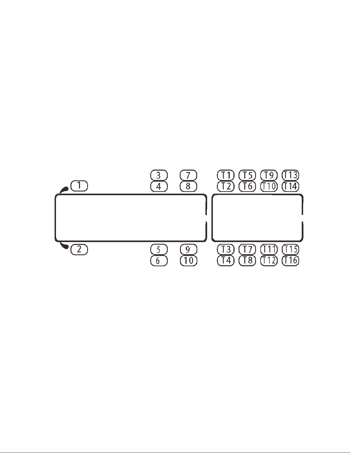
TIRE SENSOR PLACEMENT DIAGRAM ........................................................................................... 37
SYSTEM COMPONENTS Anti-Theft sensors
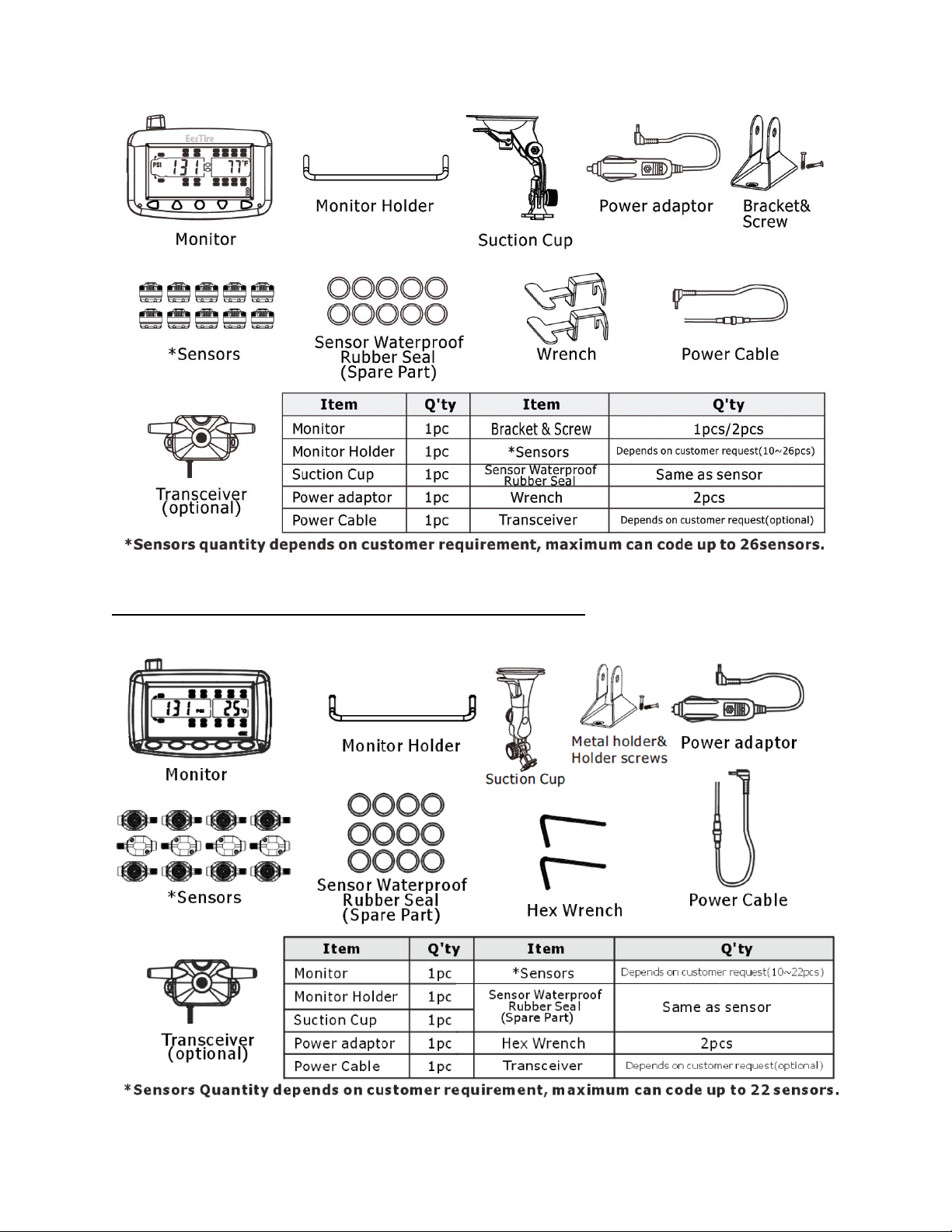
4
SYSTEM COMPONENTS-Flow-Through sensors
5
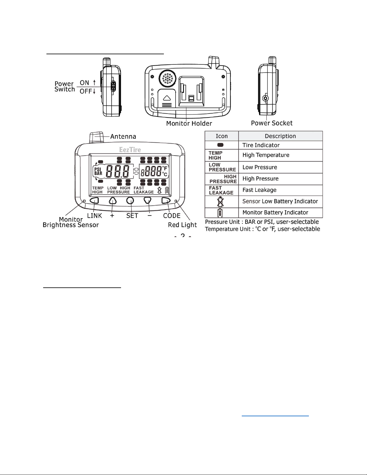
Monitor Components & Icons
This EEZ RV PRDUCTS EezTire E518 Tire Pressure and Temperature Monitoring System (TPMS) is a heavyduty versatile system designed to operate on a variety of vehicles. (i.e. Motor Coach, 5th Wheel, Travel
Trailer, Auto, Trailer, Big Rig, Farm and Mining Equipment).
SYSTEM OVERVIEW
The system comes with a monitor that can handle 26 wheels with pressures up to 210 psi. The sensors
are lightweight and do not affect the tire balance and have easy to change replaceable cr1632 batteries.
The system offers a method of dropping either the towing vehicle or the towed vehicle separately. This
allows you to monitor the towing vehicle without a towed or the towed when driving away from the
towing vehicle.
The monitor scrolls automatically through each wheel measuring tire pressure and temperature,
displaying it on the monitor. Alarms can be preset by the operator so visible and audible alarms can
warn the driver of a catastrophic failure (rapid air pressure loss), high or low pressures and high
temperature. The alarms and monitoring are sent wirelessly in real time to the cab allowing the
operator to monitor tires that are out of their vision. The audible alarm eliminates the need to watch
the monitor continually.
Tire Pressure can be displayed in PSI or Bar and temperature in Fahrenheit (F) or Celsius (C). Pressure
alerts can be set to a different pressure setting for each axle, so additional towed trailers or vehicles are
no problem. An optional booster can be purchased from your dealer or at www.eezrvproducts.com if
you have signal loss due to distance, structural or electronic interference.

6
The monitor has a rechargeable Lithium Ion battery. Sensors come with either the Anti-Theft security
feature or Flow-Through feature, and the monitor comes with both an auxiliary charger and a hard wire
cable at no extra charge.
The EEZ RV PRODUCTS Eez Tire E518 TPMS System offers both easy installation and one of the largest
LCD monitors on the market.
GENERAL INFORMATION
A tire professional or your owner’s manual should be used to determine the proper tire pressure for
your vehicle. Recommended operating tire pressures should be set when the ambient temperature is
low or cold.
Dramatic changes in tire pressure can occur because of; increased or decreased ambient temperature,
tire contact surface temperature, wheel and axle loads, sun shining on a side, etc. These and other
conditions should be taken into consideration when setting initial tire operating pressures.
This system cannot warn you of side wall failures; however, it can
supply you with irregular pressures and temperature information that may help to prevent this. If the
monitor is shut off overnight simply switch the monitor back on before departure and your real-time tire
pressures and temperatures will be updated and typically appear on the screen within 5 to 10 minutes.
Even if the monitor is in the sleep mode the system is always monitoring and will alarm should any
pressure settings or temperatures be out of your set parameters.
The Schrader Valve (core - inside the valve stem) should be the correct size, be in good condition and be
able to be depressed fully to allow the release of air to the sensor so it can operate. Some valve stem
extensions may cause inaccurate readings if they do not enable the sensor to work correctly, metal
bodied stems, or T-Valve type is recommended for best performance. Should you have difficulty with a
pressure sensor not working properly, we recommend that you contact a tire professional to ensure that
the tire stem and Schrader Valve are installed and operating properly. If using internal tire sealants or
balancing compounds/beads check with the manufacturer to ensure they are compatible with TPMS
systems or that you have filtered valve cores installed. Over a period, tires may lose pressure naturally,
through the tire itself or for other reasons such as rim leakage, etc. After installing the sensors on a tire
valve stem, it is recommended to perform a soapy water test using 1/4 dish soap and 3/4 water. Spray
the soapy solution on the valve stem and sensor area to ensure the sensor is seated all the way. If air
bubbles are seen in any of these areas, the tire may deflate. The wheel sensors are weatherproof and
can be run in the rain.
Consulted a tire professional if any of these areas prove to be a problem.
Purchasers of this product should not solely rely on this tire pressure monitoring system for safety and
should check the condition and pressure of their vehicle’s tires on a regular basis as described by the
manufacturer of the vehicle or tire manufacturer. Please note, the EEZ RV PRODUCTS EezTire T515/ SP
TPMS System operates on an RF system, as with many RF tire systems this system can occasionally suffer
from interference depending on the location of the system; thus, causing the system to be inaccurate or
not operate at all. Tire pressures and temperatures are not the only things that can affect tire safety; we
suggest daily visual inspections and periodic checks by tire professionals.
PRODUCT FEATURES
Monitor Features
• Reliable and easy to install.
• Large 3 1/2-inch LCD screen.

7
• Built-in rechargeable lithium ion battery.
• Automatic light sensor and backlight.
• Built in motion sensor.
• Configurable high/low-pressure warnings.
• Configurable high-temperature warnings.
• Visible and audible alerts.
• Selectable pressure units.
• The monitor can display in either standard or metric measurements (psi or bar/F or C)
• It monitors up to 26 tires maximum.
• Long range between sensors and monitor.
Sensor Features
• Reliable cap sensors, easy to install.
• Water resistant.
• Replaceable sensor batteries.
• Fast leak alert.
• Individually coded sensors.
Repeater/Booster Features (optional part)
• Maintains signal stability.
• Records sensor ID, trailer ID and tire pressure and temperature limits.
• Visible and audible alerts.
• Fixed alarm for high temperature (194°F)
SYSTEM SETUP
This portion is designed to make the set-up of your new EEZ RV PRODUCTS
EezTire E518 TPMS System easier and faster.
Much of the information contained in this manual is found through real life
experience using the system and passed on to hopefully make the utilization
of the system easier for you.
Please read through the guide thoroughly before starting. Complete set-up
should take approximately 20 minutes.
EEZ RV PRODUCTS EezTire E518 SYSTEM
START YOUR SET UP HERE - Step by Step Instructions:
1. Unpack all the components of your TPMS System and ensure it is
complete.
2. Take the number kit from the accessory pack and number all your
sensors as indicated below. (Hint: After affixing the number to the
8
sensor take some clear nail polish and paint over the number. This will
help ensure it stays on in inclement weather conditions.)
3. On the diagram on the last page of this manual assign the
numbered sensors to each tire as they will be put on your rig and
tow vehicle. Also fill in the tire pressures for each axel.
4. Program the alarm parameters using STEP 1 setting your system
alarm parameters.
5. Program each sensor to the monitor using STEP 2 programing
sensors to the monitor.
STEP 1: SETTING YOUR SYSTEMS ALARM
PARAMETERS
Refer to the diagram on the last page of this manual where you wrote
the “HIGH and LOW” pressure for each axel.
1. Next to each axle write down what your tire pressure is by axle and
calculate what your alarm setting will be.
2. High-Pressure setting will be (20% above axle tire pressure).
3. Low-Pressure setting will be (10% below axle tire pressure).

9
Example: Front Axle Tire Pressure is: 100 psi High-Pressure Alarm
Setting will be: 120 psi (100 psi x 1.20 (or 20%) = 120 Low-Pressure
Alarm Setting will be: 90 psi (100 psi x .9 (or 90%) = 90
These are industry standards for the initial set-up. Some adjustment
may be needed on your first trip.
For the temperature, it is recommended leaving it at the factory
default of 158 degrees F.
STEP 2: Choosing Pressure and Temperature
Unit of Measure:
PRESS and HOLD the SET button for 3 seconds until you hear the
beep. You will see PSI flashing on the left side of the screen. Press the
set button again and you can change to BAR by pressing the + or – key
to scroll between the two. When the one you want to use appears in
the screen press and release the SET button. (Pressing and releasing
the SET button in this mode is like saying yes to what the screen is
showing you)
Press the set button again and “F” will be flashing. Press + or – to
change to “c” if you like. The next time that you press the set button
the front axle will be flashing and the words “HIGH PRESSURE” will be
displayed. Follow the instructions below.
STEP 3: Choosing per Axel High and Low
Parameters:

10
Using the set key scroll to your first axel “HIGH’ pressure. Use the plus
or minus to set your HIGH PRESSURE. When you reach your desired
pressure press and release the “SET’ button again and ‘LOW
PRESSURE’ will be displayed. Use the plus or minus keys to set your
low pressure. Press the set button again and the next axel will flash
“HIGH PRESSURE”. Make your adjustments the same way as for the
first axel. Skip any axels that you are not using and just keep hitting
the “SET” button until you get to the axel that you want to set.
When you have finished setting your parameters PRESS and HOLD the
SET button until the monitor beeps and you are back to display mode.
Keep in mind that the monitor will time out in 40 seconds. So, wright
down your settings before you start.
PROGRAMMING SENSORS TO THE MONITOR
METHOD 1 tabletop (this is the easiest way)
1. Using the switch on the left side center of the monitor, push it up to
turn on the monitor. Place the monitor flat on the table in front of
you. Then place your numbered sensors on the table about a foot
away from the monitor.
2. Press and hold the CODE button on the lower right side down for 3
seconds until you hear the beep. At this time, you will see all 26 tires
on the monitor screen, and the right front tire will be flashing. After
programing only, those tires that you program will show on the
monitor. That is tire number 1. Following your diagram on the back of
your Manuel, place the first sensor on the table and push it against
the base of the monitor next to the set button. You will see “FFF FFF”
on the screen. All F's means that that sensor is not programmed yet.
Then press and release the code button one time. The monitor will

11
beep, and a random code will be displayed. Press the plus button to
go to the next tire and do the same and so on.
3. When you have programed the last sensor, press the “CODE”
button down until the monitor sets off the alarm. Then turn off the
monitor then turn it on again to make sure the tires are programed in
the right position.
4. Install your sensors to the valve stems in the order that you
programed them. Give the monitor 5 to 10 minutes to register all the
sensors. Once the sensors are synced you will not have to re-sync
unless you turn off the monitor. You can leave the monitor turned on
by the monitor’s battery power. The monitors internal battery will run
for 60 hours between charges.
NOTE:
If you get an ID LF (low frequency), error code, hit the sensor hard on
the table to wake it up and repeat. If you still get the Id LF repeat,
press the CODE button and release, pause and then press the CODE
button and release again. If it still gives ID LF then check the battery
voltage with a volt meter. The voltage on a fresh battery should be
3.2v. If it is at or below 2.8v replace the battery with a fresh one.
Method 2: AIR ACTIVATION (Most Difficult)
1. Using the switch on the left side center of the monitor push it up
to turn on the monitor.
2. Place the sensors on the tires as numbered on your diagram but
not under air pressure yet.
 Loading...