

EESiFlo 6000 Series Installation Manual
219 East Main Street
Mechanicsburg, PA
USA, 17055
Toll Free: 866-337-4356
Fax: (717) 697-2122
Simplified Installation of the
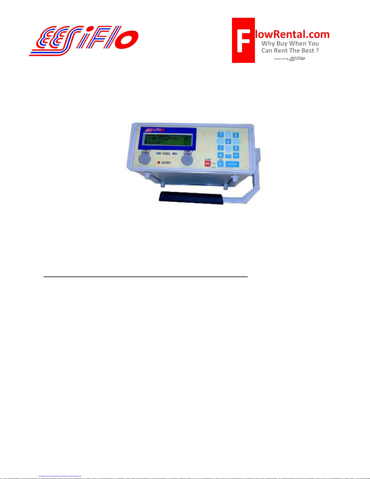
EESiFlo 6000 Series Ultrasonic Flow Computer
Setup of the 6000 Series Ultrasonic Flow Computer involves three simple steps.
1. Define the Parameters of the Pipe and Fluids (PAR on the main menu)
2. Select the Output Options (OPT on the main menu)
3. Enter the Measure Mode (MEA on the main menu)
Defining the Pipe and Fluid Parameters >PAR<
1) Start by turning the instrument ON by pressing the ON/C button
2) Plug the Transducers into the receptacle marked Channel A (or B) and the 6000 will
automatically detect which transducers are installed by displaying that information on the LCD.
3) Using the 4 or 6 keys scroll to PAR (parameters) on the main menu and press ENTER.
4) Press ENTER again to view Channel A Parameters or use the 2 and 8 keys to select
Channel B.
5) Enter the pipes Outer Diameter then press ENTER. Remember, this is the OD of the pipe
not the pipe size. For example a 2 inch pipe has an Outside Diameter of 2.375 inches.
6) Or, if the pipes diameter is not known, simply enter 0.00 and the 6000 will prompt you to enter
the Pipe Circumference.
7) Next, enter Wall Thickness
8) Select a Pipe Material using the 2 and 8 keys to scroll up and down through the available list.
9) Answer YES or NO to the prompt for Lining. If you answered YES, then enter the Lining
Type (using the 2 and 8 keys) and then the Lining Thickness
Page 1 of 3

10) Enter the internal Roughness of the pipe
11) Using the 2 and 8 keys, select the Medium (Liquid Type) from the available list.
12) Enter the approximate Medium Temperature and you'll return to the main menu.
Selecting Output Options >OPT<
1) Using the 4 and 6 keys, scroll to OPT (Output Options) then press ENTER.
2) Choose Channel A (or B) then press ENTER
3) The 6000 will prompt you for the Physical Quantities for your desired output. Use the 2 and
8 keys to scroll up and down through the available list. Press ENTER.
4) Using the 2 and 8 keys, choose your Velocity In units from the available list then press
ENTER.
5) If the 6000 is fitted with temperature inputs, answer NO to the prompt for Temperature T1
and Temperature T2 then press ENTER
6) Choose a Damping (averaging) time in seconds then press ENTER
7) Answer NO to Store Measured Data (if you’d like to store data, answer YES here) then
press ENTER
8) Unless you have a Serial Printer attached to the 6000, answer NO to Serial Output then
press ENTER
9) If the 6000 is fitted with a 4 to 20 mA output, answer NO to Current Loop then press ENTER
and you'll return back to the main menu
Enter the Measure Mode >MEA<
1) Using the 4 and 6 keys, scroll back to MEA (Measuring) then press ENTER
2) Below each channel will appear a minus sign (-), a check mark (√) or a dot (∙). Using the 4
and 6 keys, select Channel A (or B), then ensure there is a check mark below that channel by
pressing the 2 or 8 keys. Then press ENTER
3) The next prompt to appear may be different, depending upon how the 6000 has been
initialized. If Reflection Mode appears, continue with step 4 below. If a prompt appears
asking for a Sound Path, continue with step 5 below.
4) If Reflection Mode prompt appears, choose NO and the 6000 will measure in the Direct
Mode, where the transducers are mounted on opposite sides of the pipe. If you choose YES,
the 6000 will measure in the Reflection Mode where the transducers are mounted on the
same side of the pipe. It is recommended you answer YES and mount the transducers on the
same side of the pipe. However, if problems are experienced getting good solid flow data, it is
recommended you go through the MEA routine again, this time answering NO to this prompt,
then remembering that transducers will be mounted on opposite sides of the pipe. Continue at
step #6 below.
Page 2 of 3
 Loading...