

Page 1
INSTALLATION GUIDE AND OWNER’S MANUAL
FlowCo™
ELECTRIC INSTANTANEOUS WATER HEATERS
Page 2

BEFORE ATTEMPTING ANY INSTALLATION, MODIFICATION OR SERVICE OF THIS
HEATER, MAKE SURE THE ELECTRICAL POWER IS DISCONNECTED.
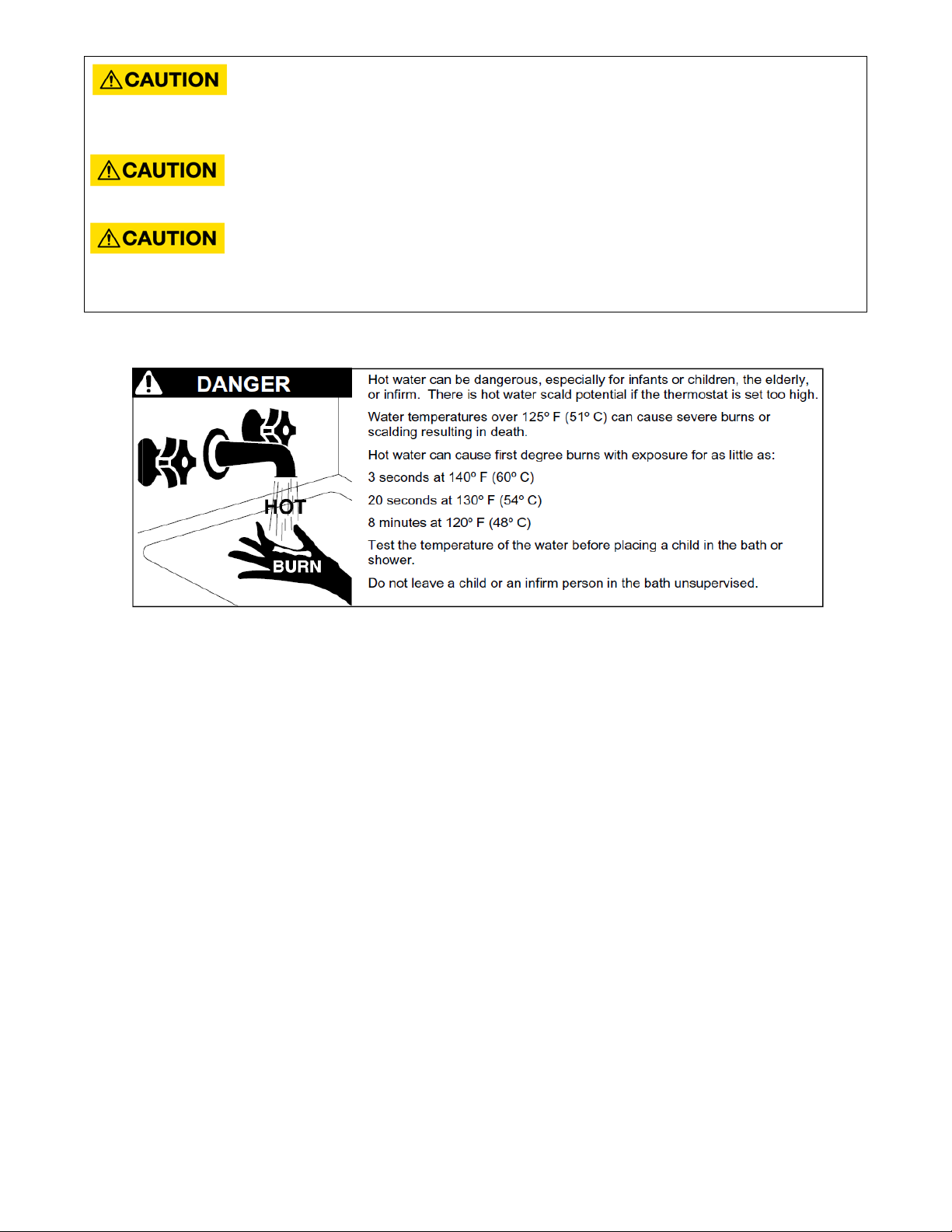
Read and understand the instructions thoroughly before attempting the installation or service of this water
heater. Failure to follow the instructions can result in serious injury, death and/or property damage. The
warranty of the water heater will depend upon proper installation according to the instructions. Some heaters
come supplied with separate faucet aerators. If supplied, the aerator must be installed in the faucet for
optimum performance. The heater must only be used to heat water and must be installed in a location where it
is not subject to freezing temperatures. The manufacturer is not liable for any damages resulting from improper
installation or misuse.
The installation must conform to the latest requirements of the National Electrical Code and all applicable state
and local codes. This information is available through local authorities. You must understand the requirements
before beginning this installation.
This unit is not required by UL 499 to employ a temperature and pressure relief valve (T&P). You should check
with local codes to find out if one is required. If it is, it must be installed in the outlet hot water pipe between
the heater and the isolation valve.
IMPORTANT SAFETY INSTRUCTIONS
When using this electrical equipment, basic safety precautions should always be followed, including the
following:
READ AND FOLLOW ALL INSTRUCTIONS
Supply this appliance only from a grounded system. A green terminal (or a wire connector marked “G”, “GR,
“Ground”, or “GROUNDING”) is provided for wiring the appliance. To reduce the risk of electric shock, connect
this terminal or connector to the grounding terminal of the electric service or supply panel with a continuous
copper wire in accordance with the electrical installation code.
Contents
GENERAL .................................................................................................................................................................... 3
1) MOUNTING THE UNIT TO THE WALL .................................................................................................................... 4
2) PLUMBING HOOK-UP ............................................................................................................................................ 5
3) ELECTRICAL HOOK-UP ........................................................................................................................................... 8
4) COMMISSIONING THE HEATER ........................................................................................................................... 10
5) TROUBLESHOOTING ............................................................................................................................................ 13
6) PERIODIC MAINTENANCE .................................................................................................................................... 14
7) PART NUMBERS FOR FITTINGS, AERATORS AND AERATOR ADAPTORS ............................................................. 15
8) REPAIR PARTS FOR FLOWCO UNITS .................................................................................................................... 15
2
Page 3
DO NOT INSTALL IN A BATH ENCLOSURE OR SHOWER STALL OR CONNECT TO A SALT-
REGENERATED WATER SOFTENER OR A WATER SUPPLY OF SALT WATER. ATTENTION:
NE PAS INSTALLER DANS UNE BAIGNOIRE OU UNE CABINE DE DOUCHE ET NE PAS BRANCHER À UN
ADOUCISSEUR D’EAU RÉGÉNÉRÉ AVEC DU SEL OU À UN APPROVISIONNEMENT EN EAU SALÉE.
(CANADIAN INSTALLATIONS ONLY) CONNECT ONLY TO A CIRCUIT PROTECTED BY A
CLASS A GROUND FAULT CIRCUIT INTERRUPTER. ATTENTION: BRANCHER UNIQUEMENT
À UN CIRCUIT PROTÉGÉ PAR UN DISJONCTEUR DE FUITE DE TERRE DE CLASSE A.
(CANADIAN INSTALLATIONS ONLY) USE COPPER CONDUCTORS ONLY. USE BONDING
CONDUCTOR IN ACCORDANCE WITH THE CANADIAN ELECTRICAL CODE PART I. UTILISEZ
DEZ CONDUCTEURS EN CUIVE UNIQUEMENT. UTILISEZ DES CONDUCTEURS DE MIZE À LA MASSE
CONFORMEMENT AU CODE CANADIEN DE L’ÉLECTRICITÉ, PARTIE I.
SAVE THESE INSTRUCTIONS
GENERAL
The Eemax, Inc.™ FlowCo is a non-thermostatic electric tankless water heater. FlowCo is specifically designed to
take in cold water and heat it to temperatures suitable for handwashing and other fixed-flow applications.
To obtain optimum performance and energy savings, the unit should be located as close as possible to the pointof-use. The unit is supplied with compression rings and nuts suitable for direct coupling to 3/8” copper or PEX™
piping. Do not use additional screwed fittings, pipe dope or teflon tape – doing so will void the warranty. DO
NOT SOLDER PIPES WHILE THE UNIT IS INSTALLED as serious damage to the heater will result and the warranty
will be voided.
3
Page 4
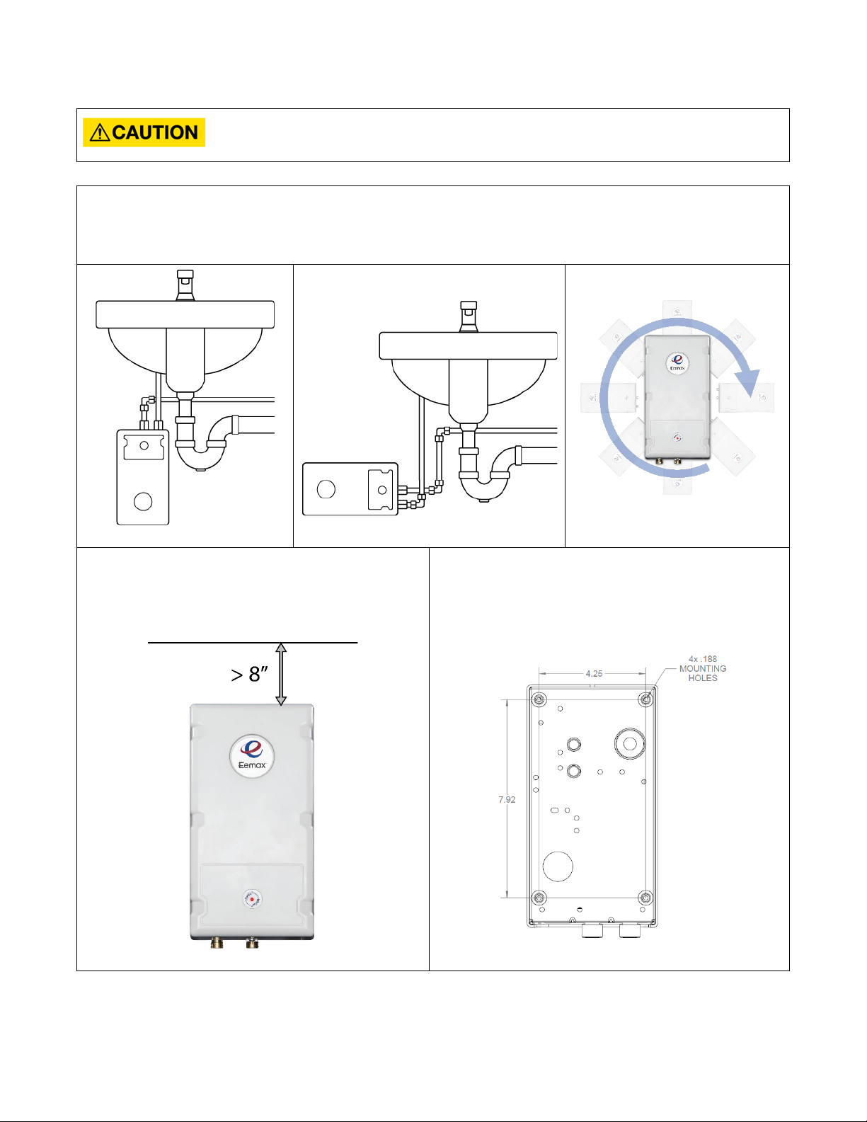
1) MOUNTING THE UNIT TO THE WALL
THIS HEATER MUST BE INSTALLED IN A LOCATION WHERE IT IS NOT SUBJECT TO
1.
2.
3.
FREEZING TEMPERATURES.
The heater should be mounted on the wall under the sink, as close to the point-of-use as possible. Ideal
position is fittings pointed down, but the heater can be mounted in any orientation.
Make sure to leave a minimum of 8 inches service
clearance at the end OPPOSITE the fittings.
Remove the cover and fasten to the wall using the
four mounting holes at each corner of the back plate.
Replace the cover.
4
Page 5
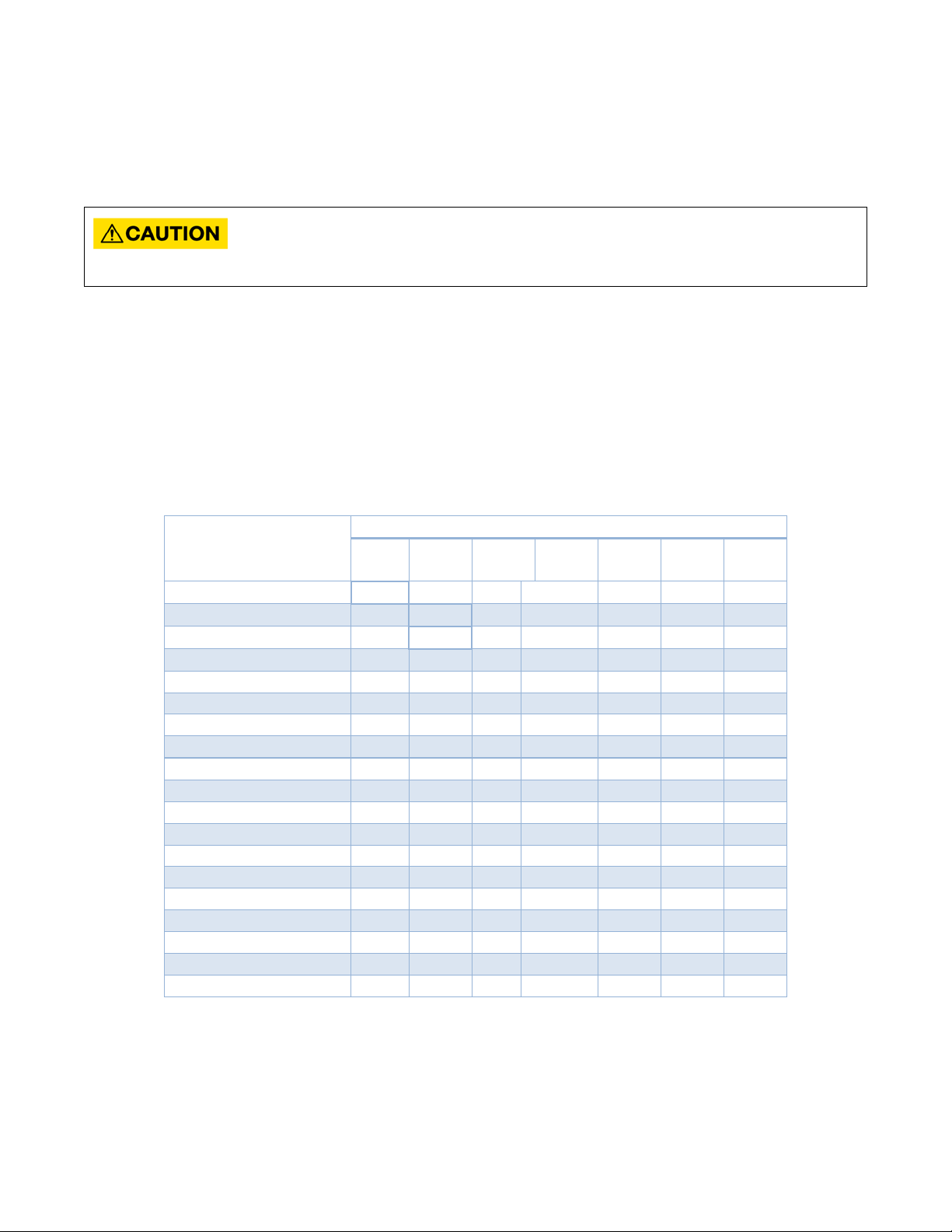
2) PLUMBING HOOK-UP
Turn On Flow Rate, GPM (LPM)
0.2
(0.76)
0.25
(0.95)
0.3
(1.14)
0.4
(1.51)
0.5
(1.89)
0.7
(2.65)
0.8
(3.03)
SPEX1812
•
SPEX2412
•
SPEX3012
•
SPEX3512
•
SPEX35
•
SPEX48
•
SPEX55
•
SPEX65
•
SPEX75
•
SPEX95
•
SPEX3208
•
SPEX4208
•
SPEX8208
•
SPEX3277
•
SPEX4277
•
SPEX60
•
SPEX80
•
SPEX90
•
SPEX100
•
NEVER SUBSTITUTE THREADED PIPE FITTINGS USING PIPE DOPE OR TEFLON TAPE AND
The heater is supplied with 3/8” brass compression fittings that are compatible with either copper or plastic
pipes. Make sure these fittings are used for this installation. Contact your Eemax representative for further
information.
NEVER SOLDER ANY PIPE CONNECTIONS WHILE ATTACHED TO THIS HEATER BECAUSE
DAMAGE TO THE HEATER WILL RESULT. DOING THIS WILL VOID THE WARRANTY!
Eemax strongly recommends that the heater be supplied directly from the main cold water trunk line when
possible. This helps to avoid a potential water flow interruption to the heater which could lead to a failure of the
heating element.
System Requirements:
• Minimum/maximum working pressure: 30 PSI/150 PSI
• Optimal operating pressure range: 35 to 80 PSI
• Minimum turn on flow rate is model dependent (refer to the table below)
Base Model*
*Special suffixed models (i.e. CA, etc.), will have identical temperature rises as their base model
For optimum performance, Eemax recommends the use of isolation valves (full flow ball type) on the inlet and
outlet pipes.
5
Page 6

BEFORE ATTEMPTING ANY INSTALLATION, MODIFICATION OR SERVICE OF THIS HEATER,
MAKE SURE THE ELECTRICAL POWER IS DISCONNECTED.
1.
2.
with the heater connections to minimize stress on the
3.
The heater’s water INLET and OUTLET are labeled.
Install full flow ball valves to the inlet and outlet pipes and
run water through the inlet pipe into a bucket to purge it of
any debris. Close the inlet ball valve.
Make sure the inlet filter screen is present in the inlet
fitting and the inlet and outlet pipes are correctly aligned
heater.
Remove the cover. Connect the pre-assembled inlet and
outlet pipes to the heater (do not overtighten compression
fittings) and fully open the inlet and outlet ball valves.
Check the system for water leaks at all plumbing
connections. If a leak is present at the compression fitting,
slowly tighten compression nut until it stops – do not
overtighten.
6
Page 7

4.
Open the hot water faucet and run water for a
minimum of 60 seconds and until the flow is continuous
and free of air pockets. Close the faucet and install the
aerator (if supplied).
Failure to install aerator will result in less-than-favorable
heater performance.
7
Page 8

3) ELECTRICAL HOOK-UP
BEFORE BEGINNING ANY WORK ON THIS INSTALLATION, CONFIRM THE ELECTRICAL
Voltage
(VAC)
Max power
(kW)
Max current
(A)
Minimum wire size
(AWG) @75°C
SPEX1812
120
1.8
15
14
SPEX2412
120
2.4
20
14
SPEX3012
120 3 25
12
SPEX3512
120
3.5
29
10
SPEX35
240
3.5
15
14
SPEX48
240
4.8
20
14
SPEX55
240
5.5
23
12
SPEX65
240
6.5
27
10
SPEX75
240
7.5
32
10
SPEX95
240
9.5
40
8
SPEX3208
208 3 15
14
SPEX4208
208
4.1
20
14
SPEX8208
208
8.3
40
8
SPEX3277
277 3 11
14
SPEX4277
277
4.1
14.8
14
SPEX60
277 6 22
12
SPEX80
277 8 29
10
SPEX90
277 9 33
10
SPEX100
277
10
36
8
BREAKER IS “OFF” AND THAT ALL MOUNTING AND PLUMBING WORK HAS BEEN
COMPLETED PER THE STATED INSTRUCTIONS.
For use on an individual branch circuit only.
The heater shall be installed using insulated, UL listed, 2 wire cable (2 wire plus ground) of the appropriate size
suitable for up to 75°C and protected by the correctly rated circuit breaker. Refer to the chart below for
recommended copper wiring for conductors with a temperature rating of 75°C:
ELECTRICAL SPECIFICATIONS
Base Model*
*Special suffixed models (i.e. CA, etc.), will have identical temperature rises as their base model
8
Page 9

1.
Power cable entry to the heater should be made
2.
FAILURE TO GROUND THE SYSTEM MAY RESULT IN SERIOUS INJURY, DEATH AND/OR
3.
through one of the knock-out holes located on the
back plate or top/bottom ends of the unit. Use the
appropriate strain relief fitting.
The power leads are to be secured to the L1 and
L2 or L and N connectors on the terminal block or
relay. The ground lead is to be secured to the GND
connector on the block or the green ground wire
with the provided wire nut.
PROPERTY DAMAGE.
Leave the breaker in the “OFF” position. Proceed
to the next section:
COMMISSIONING THE HEATER
9
Page 10

4) COMMISSIONING THE HEATER
1.
2.
3.
4.
BEFORE SWITCHING THE ELECTRICAL BREAKER “ON”, VERIFY THE INLET AND OUTLET
BALL VALVES ARE FULLY OPEN AND WATER IS FLOWING THROUGH THE HOT WATER
FAUCET FOR A MINUTE OR TWO UNTIL THE FLOW IS CONTINUOUS AND FREE FROM AIR POCKETS. DO NOT
SWITCH THE BREAKER “ON” IF THERE IS A POSSIBILITY THE WATER IN THE HEATER IS FROZEN.
Verify water is flowing through the faucet.
Switch “ON” the electric power supply at the breaker.
The InfoCue™ will flash rapidly while water flows
through the unit. Maintain flow.
After 15 seconds, the InfoCue will turn solid red and
there will be an audible click.
The heater is commissioned at this point.
The faucet can be turned off and used as needed. With no
flow, the unit will flash every 4 seconds, indicating normal
stand-by mode.
10
Page 11

Congratulations!
GPM (LPM)
0.2
(0.76)
0.25
(0.95)
0.3
(1.14)
0.4
(1.51)
0.5
(1.89)
0.7
(2.65)
0.8
(3.03)
1.0
(3.79)
1.5
(5.68)
61
(34)
49
(27)
41
(23)
31
(17)
25
(14)
18
(10)
15
(8)
12
(7) 8 (4)
82
(46)
66
(37)
55
(31)
41
(23)
33
(18)
23
(13)
20
(11)
16
(9)
11
(6)
82
(46)
68
(38)
51
(28)
41
(23)
29
(16)
26
(14)
20
(11)
14
(8)
80
(44)
60
(33)
48
(27)
34
(19)
30
(17)
24
(13)
16
(9)
80
(44)
60
(33)
48
(27)
34
(19)
30
(17)
24
(13)
16
(9)
82
(46)
66
(37)
47
(26)
41
(23)
33
(18)
22
(12)
75
(42)
54
(30)
47
(26)
38
(21)
25
(14)
63
(35)
55
(31)
44
(24)
30
(17)
73
(41)
64
(36)
51
(28)
34
(19)
81
(45)
65
(36)
43
(24)
82
(46)
68
(38)
51
(28)
41
(23)
29
(16)
26
(14)
20
(11)
14
(8)
70
(39)
56
(31)
40
(22)
35
(19)
28
(16)
19
(11)
81
(45)
71
(39)
57
(32)
38
(21)
82
(46)
68
(38)
51
(28)
41
(23)
29
(16)
26
(14)
20
(11)
14
(8)
70
(39)
56
(31)
40
(22)
35
(19)
28
(16)
19
(11)
82
(46)
59
(33)
51
(28)
41
(23)
27
(15)
78
(43)
68
(38)
55
(31)
36
(20)
77
(43)
61
(34)
41
(23)
68
(38)
46
(26)
Your Eemax tankless electric water heater is installed and ready for use!
MAXIMUM TEMPERATURE RISE AT SPECIFIED FLOW RATE, °F (°C)
Base
Model*
SPEX1812
SPEX2412
SPEX3012 -
SPEX3512 - -
SPEX35 - -
SPEX48 - - -
SPEX55 - - - -
SPEX65 - - - - -
SPEX75 - - - - -
SPEX95 - - - - - -
SPEX3208 -
SPEX4208 - - -
SPEX8208 - - - - -
SPEX3277 -
SPEX4277 - - -
SPEX60 - - - -
SPEX80 - - - - -
SPEX90 - - - - - -
SPEX100 - - - - - - -
*Special suffixed models (i.e. CA, etc.), will have identical temperature rises as their base model
“-“Flow rate below turn on flow for this model
Note: The values shown above are only for comparison purposes.
11
Page 12

MAXIMUM DERATED TEMPERATURE RISE AT SPECIFIED FLOW RATE, °F (°C)
240VAC heaters used at 208VAC
GPM (LPM)
0.2
(0.76)
0.25
(0.95)
0.3
(1.14)
0.4
(1.51)
0.5
(1.89)
0.7
(2.65)
0.8
(3.03)
1.0
(3.79)
1.5
(5.68)
60
(33)
45
(25)
36
(20)
26
(14)
22
(12)
18
(10)
12
(7)
61
(34)
49
(27)
35
(19)
31
(17)
25
(14)
16
(9)
56
(31)
40
(22)
35
(19)
28
(16)
19
(11)
48
(27)
42
(23)
33
(18)
22
(12)
55
(31)
48
(27)
38
(21)
26
(14)
61
(34)
49
(27)
32
(18)
Base
Model*
SPEX35 - -
SPEX48 - - -
SPEX55 - - - -
SPEX65 - - - - -
SPEX75 - - - - -
SPEX95 - - - - - -
*Special suffixed models (i.e. CA, etc.), will have identical temperature rises as their base model
“-“Flow rate below turn on flow for this model
Note: The values shown above are only for comparison purposes.
12
Page 13

5) TROUBLESHOOTING
LED Pattern
Status/Problem
Possible causes
Heater response
Possible solutions
Solid light
Heating
N/A
N/A
N/A
One flash every
four seconds
Idle
N/A
- unit waits for
flow
N/A
Two flashes
Low heat
- outlet temperature below
spec
- unit keeps
- reduce flow
Two flashes
Outlet thermistor
- outlet thermistor
- unit keeps
pattern
- inspect
thermistor
Two flashes
Over-temperature
- outlet temperature exceeds
- unit keeps
-increase flow
required
Three flashes
Over-temperature
- outlet temperature exceeds
- unit stops
minimum
- increase flow
Three flashes
Freeze warning
- inlet temperature is too low
- unit shuts
- increase
specifications
CAUTION: Make certain power to unit is “OFF” before removing protective cover FOR ANY REASON.
For status resolution, please consult the table below.
once, three
second pause
twice, three
second pause
three times,
three second
pause
once, three
second pause
failure
Warning
Protection
90°F/32°C for 5 seconds of
flow
- element failure
- ECO tripped/malfunctioning
- relay/contactor
malfunctioning
- control board failure
- inlet water supply out of
interrupted or disconnected
110°F/38°C
150°F/65°C
running, LED
flashes a warning
pattern
running, LED
flashes a warning
running, LED
flashes a warning
pattern
heating until
outlet
temperature falls
below preset
through unit
connections/wiring
of outlet
through unit. If this
temperature is
desired no action is
through unit to
decrease the
overall
temperature rise
twice, three
second pause
Notes:
* “shut down” means the control board stops applying heat to the heating element, but the control board and
diagnostic functions remain active
Still having trouble? Please call our Technical Service Department.
(below 35°F/2°C)
13
down*
temperature of
inlet water to meet
product
Page 14

6) PERIODIC MAINTENANCE
The heater is designed for many years of carefree use. In order to maintain consistent water flow, it may be
necessary to periodically clean the faucet aerator or the filter screen located in the brass inlet fitting at the
heater.
Heating chamber
Energy cut-off
(ECO)
Contactor Relay
Control board
Element cartridge
installs inside heating chamber
14
Page 15

7) REPLACEMENT PART NUMBERS
3/8" NUT
EX68B
3/8" SLEEVE
EX68C
SPEX1812
EX800 PRT
EX383
EX250B
SPEX2412
EX610
EX383
EX250B
SPEX3012
EX480
EX383
EX250B
SPEX3512
EX410
EX383
EX250B
SPEX35
EX1650
EX383
EX254
SPEX48
EX1200
EX383
EX254
SPEX55
EX1050
EX383
EX254
SPEX65
EX890
EX383
EX254
SPEX75
EX770
EX383
EX255B
SPEX95
EX630
EX383
EX255B
SPEX3208
EX1440
EX383
EX254B
SPEX4208
EX1050
EX383
EX254B
SPEX8208
EX520
EX383
EX255B
SPEX3277
EX260
EX383
EX251B
SPEX4277
EX1870
EX383
EX251B
SPEX60
EX1280
EX383
EX251B
SPEX80
EX960
EX383
EX251B
SPEX90
EX850
EX383
EX253B
SPEX100
EX760
EX383
EX253B
COMPRESSION FITTINGS
8) REPAIR PARTS FOR FLOWCO UNITS
Base Model
Element
Cartridge
Control
Board
Relay
If you need any assistance from our Technical Service Department, make sure you can identify this water heater
by having the model no:____________________ and serial number:_____________________.
203-267-7890 or toll free: 800-543-6163.
Call
Eemax Inc., 400 Captain Neville Drive, Waterbury, CT 06705
Tel: 800-543-6163, 203-267-7890, Fax: 203-267-7975, email: support@eemaxinc.com
15
Page 16

Notes:
Eemax Inc., 400 Captain Neville Drive, Waterbury, CT 06705
Tel: 800-543-6163, 203-267-7890, Fax: 203-267-7975, email: support@eemaxinc.com
EX07200-87 Rev C
16
 Loading...