

Page 1
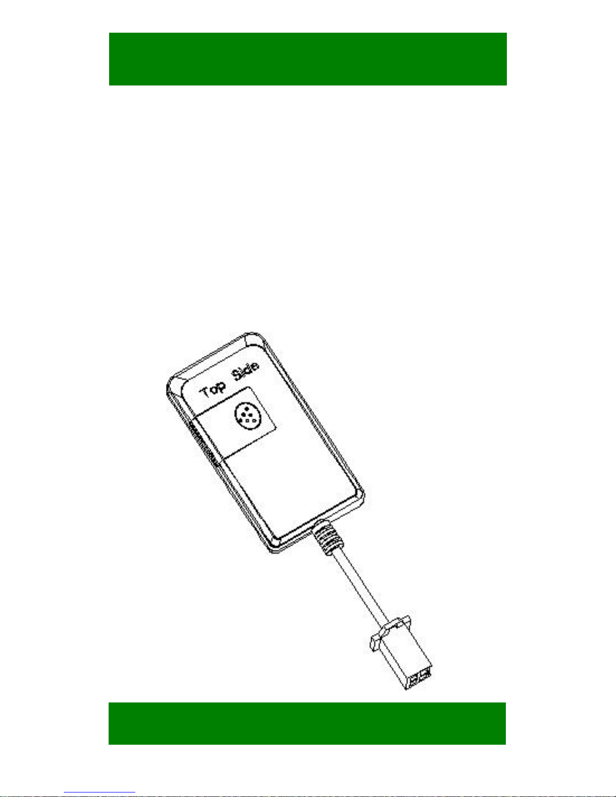
GPS
GPS
Tracker
Tracker —
For Vehicle
<GPS+GSM+SMS/GPRS>S
User Manual
V1.6
MODEL:TK115
Professional Tracking System
Page 2

2
CATALOG
Ⅰ. Product Features....................................... 5
Ⅱ. Components and Accessories................7
Ⅲ. SIM card Installation............................... 8
3.1 Before Installation............................8
3.2 Install the SIM card..........................8
3.3 Uninstall the SIM card..................... 9
Ⅳ. Terminal Installation............................. 10
4.1 Install terminal............................... 10
4.2 Terminal wiring definition............. 12
4.3 Relay wiring...................................14
Ⅴ. Power on terminal..................................15
5.1 Power on.........................................15
5.2 LED Indicators...............................15
Ⅵ. Inquiry/Monitoring/Cut Oil....................16
6.1 Inquiry by SMS..............................16
6.2 Inquiry by service platform............16
6.3 Cut off/Recover Oil circuits........... 17
Page 3

3
Ⅶ. Set up terminal......................................17
Ⅷ. Terminal Alarm.....................................17
8.1 Vibration Alarm(B type).................17
8.2 Collision / falling Alarm(B type)... 18
8.3 Speed Alarm................................... 18
8.4 Geo-fence Alarm............................ 18
Ⅸ. Trouble shooting................................... 19
9.1 Cannot connect to the platform......19
9.2 Offline status on the platform.........19
9.3 Not positioning for a long time...... 20
9.4 Position drift is serious...................21
9.5 Commands receiving abnormally.. 21
Ⅹ. Warranty Rules.......................................21
10.1 Special statement..........................21
10.2 Warranty period............................22
10.3 After sales.....................................22
Warranty card............................................ 22
Page 4

4
Welcome to use our terminal
,
please
read this manual carefully to install
and operate terminal exactly. This
user manual is for reference only. If
some contents and operation steps
are inconsistent with those for the
actual product, the latter will prevail.
Using GPS tracker, we can position,
monitor and control the vehicle on
the position server via GPRS, GPS
and Internet. It can help customers
to manage transparently, reduce
cost, maintain security and raise
efficiency. Now it is widely used in
business traffic, logistics distribution,
automobile lease, intelligent
transportation, shipping market,
army and police, rescuing, Safety
Supervision, Intelligent city…
Page 5

5
Ⅰ. Product Features
■Supports quad bands,
i.e. 850/900/1800/1900MHz,
universal in the world.
■Wide Input Voltage:9-60V DC.
■GPS precise positioning with A-GPS and
uploaded by GPRS regularly, Supports
real-time tracking and history track playback.
■Web browser platform, Smart phone app
platform and SMS query.
■Supports multiple alarm,acceleration sensor
can be added (B models, optional component),
so as increase vibration, collision and falling
alarm.
■Supports ACC status checking and vehicle
status notifying.
■Use relay to remotely control the vehicle.
■Multiple protocol support, OTA upgrade
program.
Page 6
6
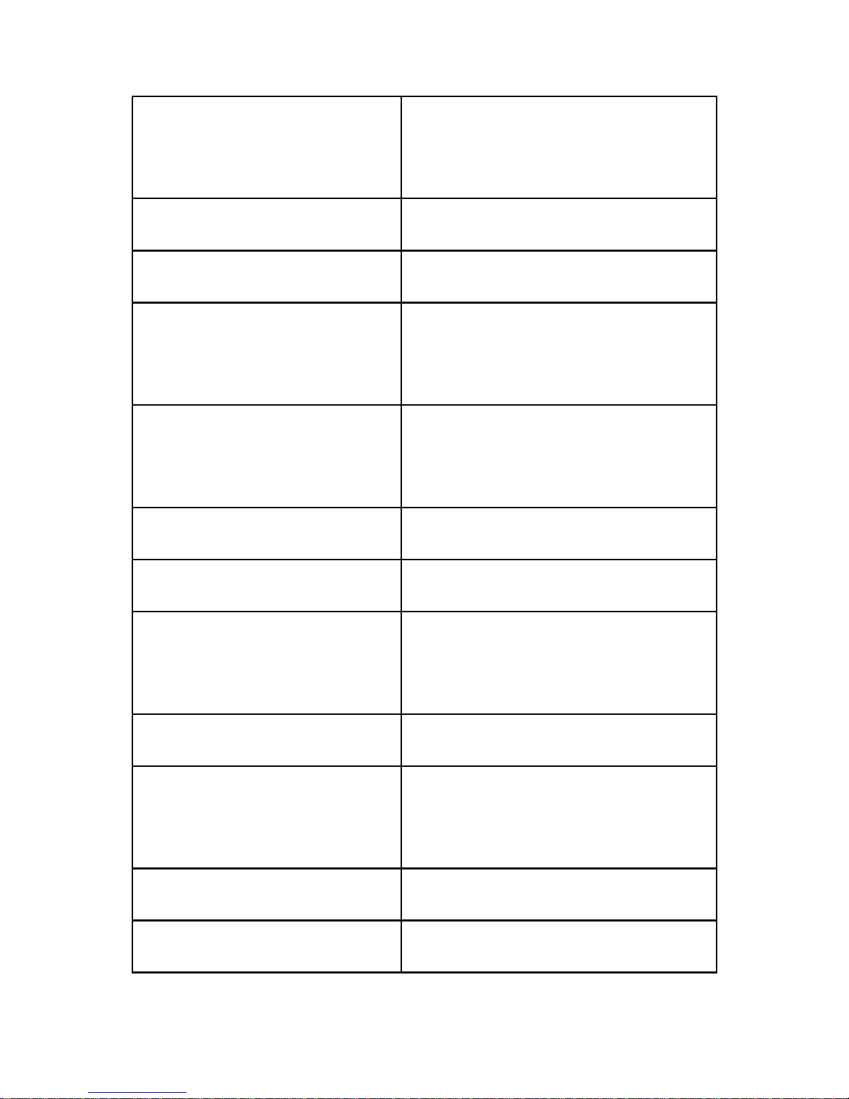
Basic Specifications
Voltage
12VDC/24VDC/48VDC/60
VDC
Standby Current
<10mA@12V
Work current
<30mA@12V
GPS positioning
accuracy
15m
GSM positioning
accuracy
100m
GPS Frequency
1575MHz
GSM Frequency
850/900/1800/1900MHz
Hot/warm/cold start
time
<3s,<15s,<60s
Dimensions (mm)
71.8(L)X38.5(W)X10.5(H)
Operating
temperature
-20℃~70℃
Operating humidity
20%~80%RH
Net Weight
42 g
Page 7
7
Ⅱ. Components and Accessories
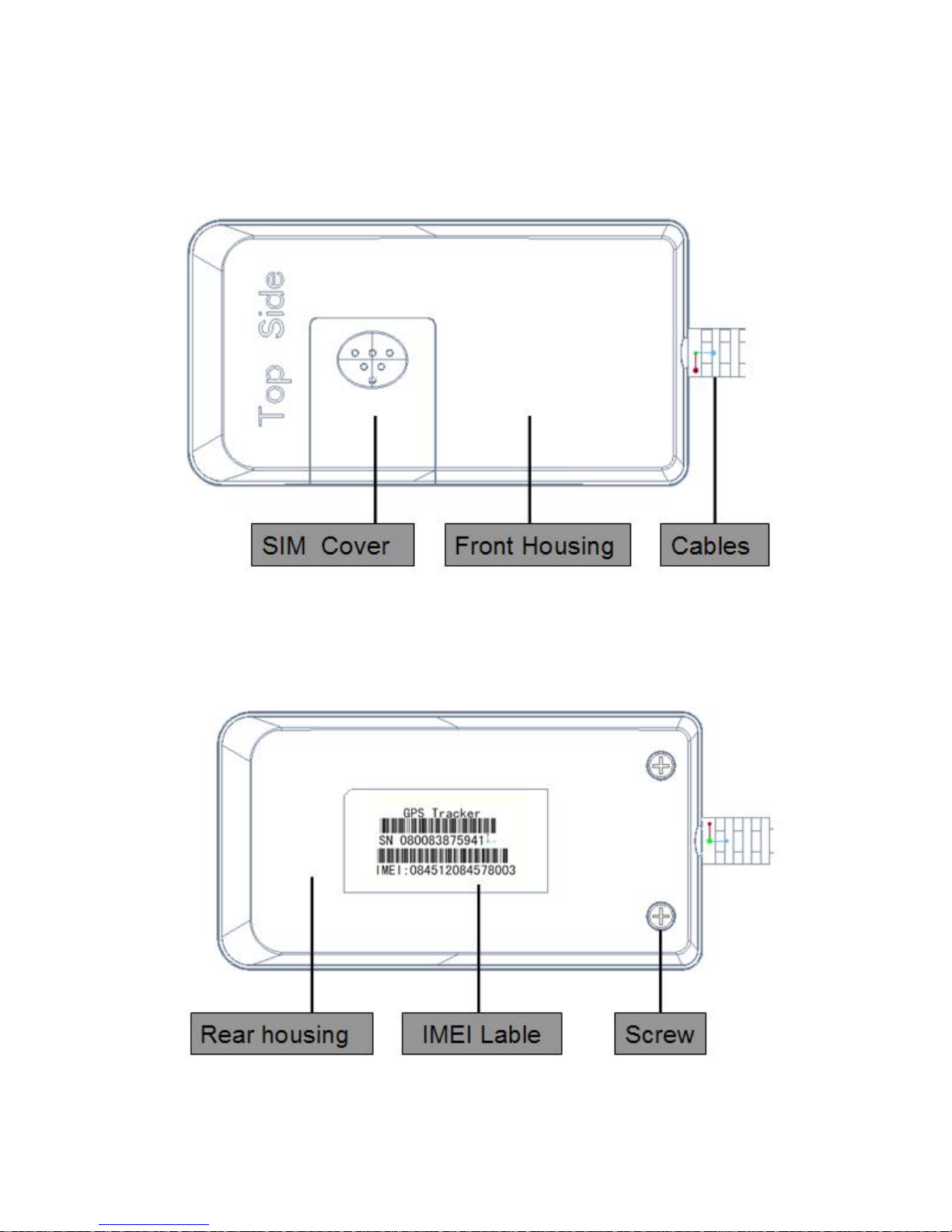
■ 2.1 Components
-Top Front-
-Top Back-
Page 8
8
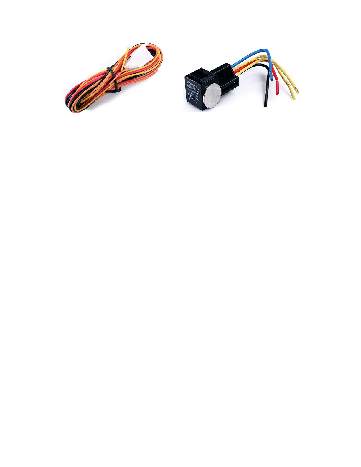
■ Accessories(reference pictures)
Power Cables(Default) Relay(Optional)
Relay for remote cut off / resume oil, Please
note that function need the device equipped
with the matched accessories.
Ⅲ. SIM card Installation
3.1 Before Installation
Check device and accessories are intact, or
please contact your dealer;
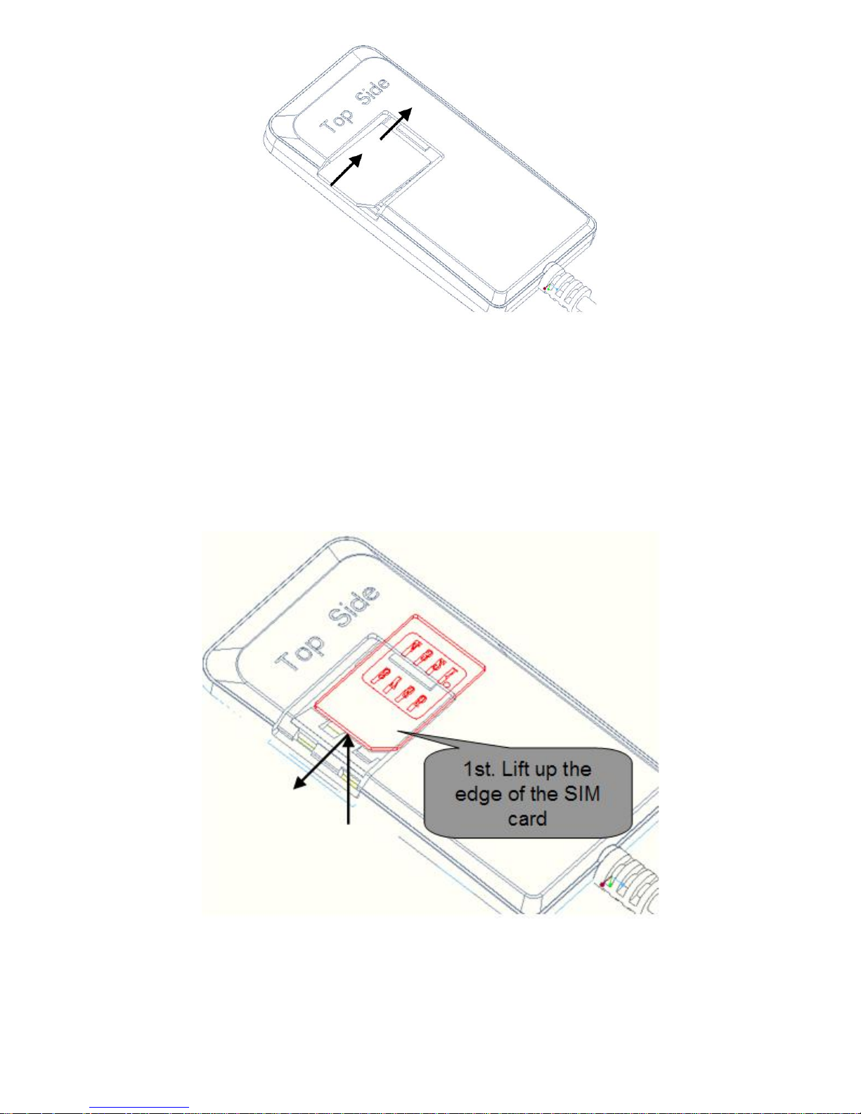
3.2 Install SIM card
A suitable SIM card needed for using terminal;
Page 9
9
1. Insert the SIM card until cannot move it inside
anymore;
2. Pull the SIM card back a bit;
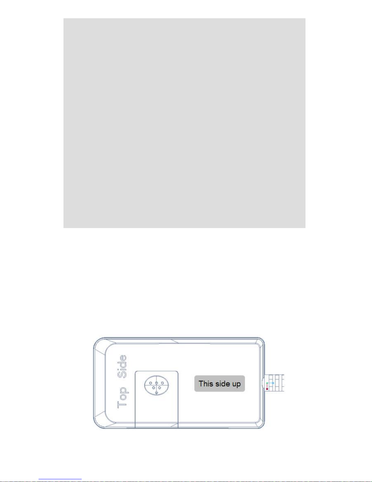
3.3 Uninstall SIM card
1. Lift up the edge of the SIM card;
2. Pull out the SIM card.
Note:
Page 10
10
●Please cut off the power before installing or
uninstalling the SIM card.
●The SIM card should support GPRS and the
GPRS should be opening.
●Inquiry by call needs the SIM card supporting the
calling line identification presentation.
●If you enable the PIN code of the SIM card,
please use your mobile phone to disable the PIN
code.
●Please make sure that the SIM card has sufficient
balance.
Ⅳ. Terminal Installation
4.1 Install terminal
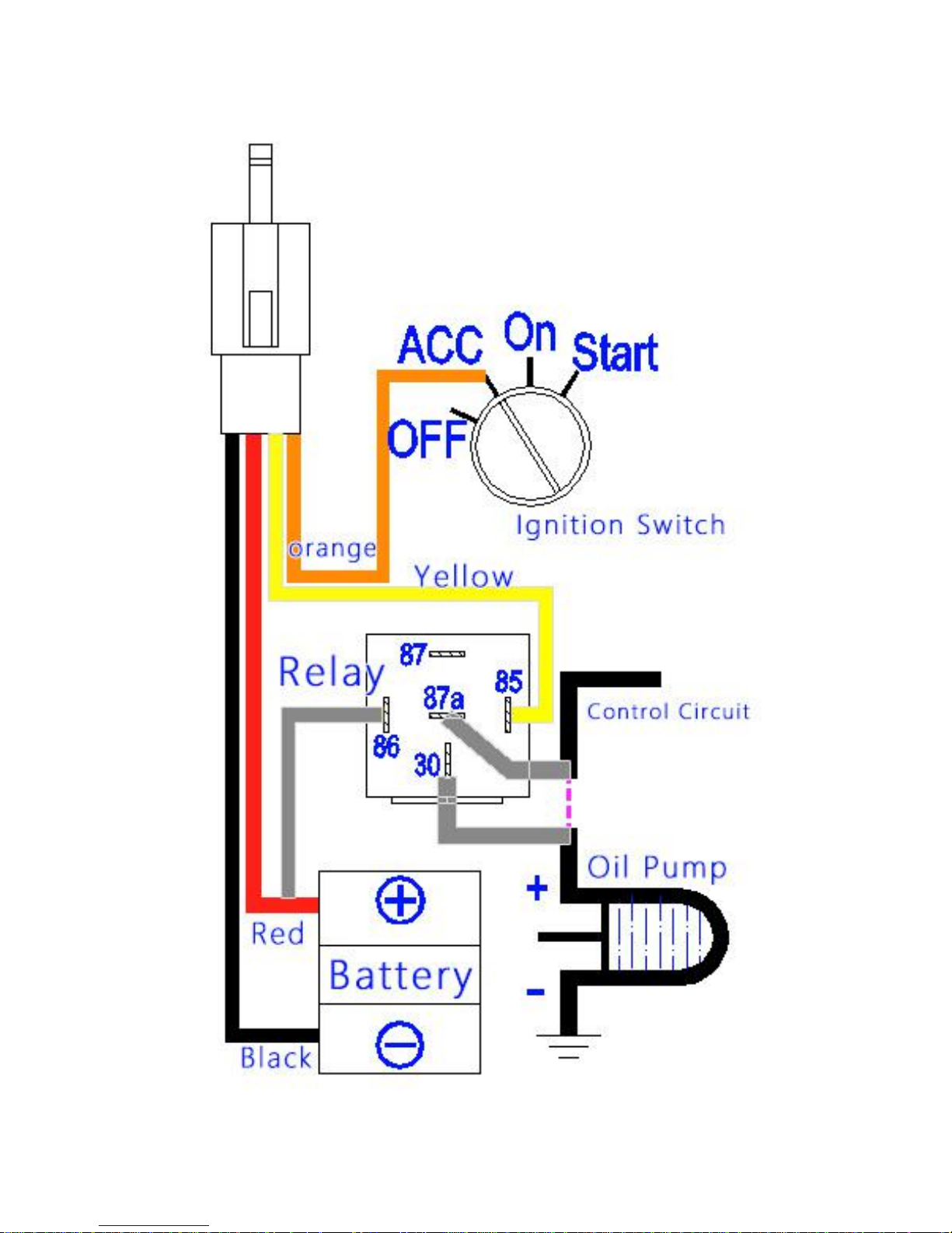
4.1.1 Suggest to install terminal concealed by the
dealer designated professional body.
Please make sure to install terminal with this side
Page 11

11
upward, and use wide strong double-sided
adhesive sponge to fix it.
4.1.2 Installation Notice
●Hide terminal properly inside the car body in order
to avoid damages.
●Keep terminal away from RF emission sources
such as backing radar, car burglar alarm and other
vehicle mounted communication devices.
●Suggest to use wide strong double-sided
adhesive sponge to fix it, or use cable ties and
other liable methods to fix it.
●Device Built-in GSM antenna and GPS antenna,
Installation should ensure that the receiving side
facing up (towards the sky) without metal cover on
the top of it, otherwise may weaken the antenna
signal,Cause the device to not work correctly.
The recommended installation location:
1)The hiding place below the front windshield trim
panel;
2)The hiding place around the front dash(if the
surface is not made of metal);
3)The place under the rear windshield;
Page 12
12
4.2 Terminal wiring definition
Total schematic wiring terminal
Page 13
13
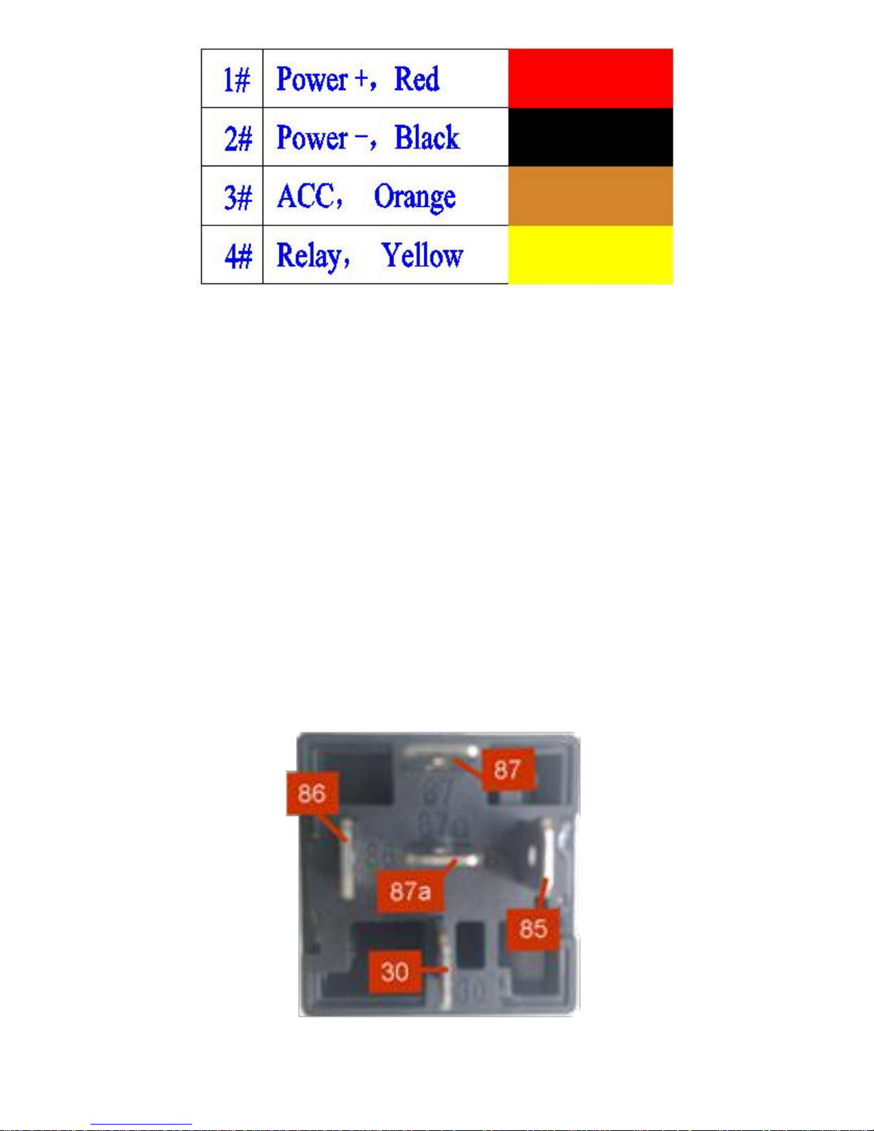
4.2.1 Power cables and other interface for remote
control
The standard input voltage of terminal is 9V-60VDC,
so please choose the our original power cables, the
red cable is positive and the black cable is negative;
Please ground the negative pole separately or
ground it to ground connection, not to any other
ground.
Connect the ACC cable (orange cable) to ACC
switch of the vehicle, then the position server can
get the information about the vehicle power; the
ACC cable can also be connected directly to the
positive pole of the vehicle power, then the position
server think that the vehicle is always ignited.
Connect the 4# cable (yellow cable) to the 85
terminal(with small yellow cable) of the relay. Use
cable ties to fix the relay to waterproof place, or use
plastic bags to cover the relay..
Page 14
14
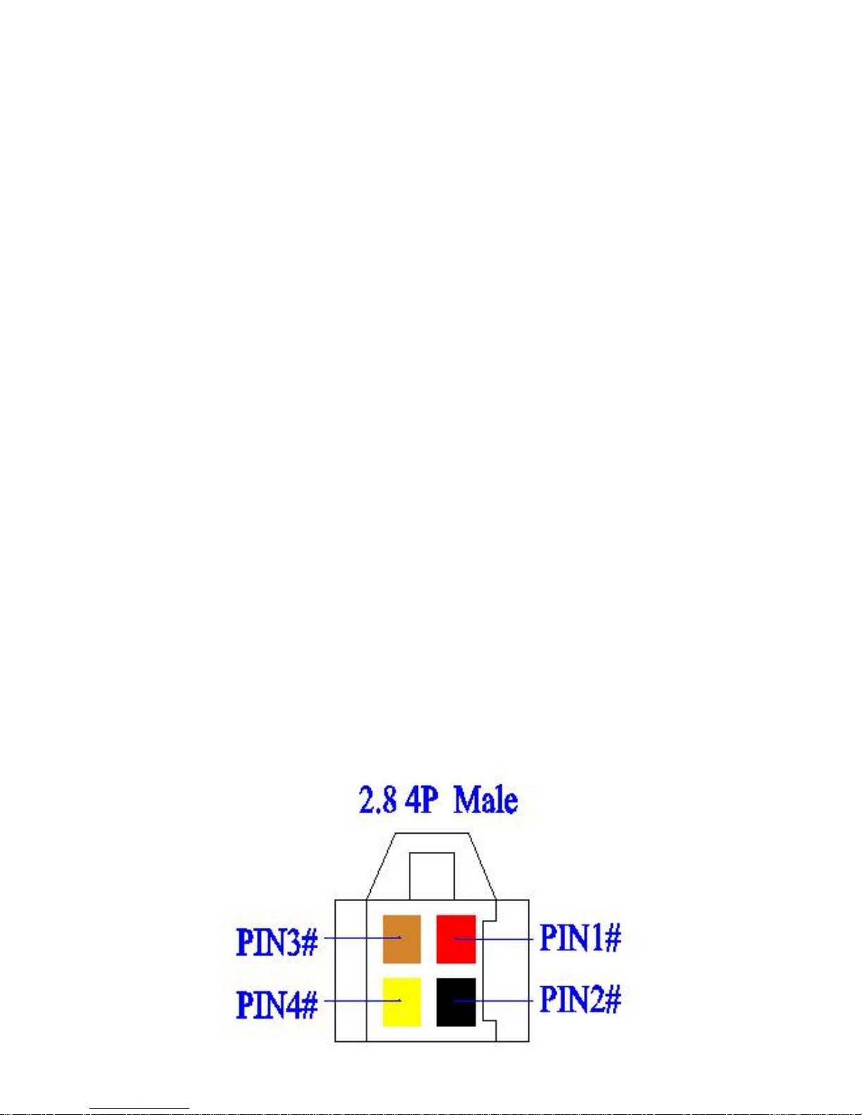
4.3 Relay wiring
Relay wiring diagram shows how to wire the relay to
control the fuel pump:
4.3.1 Connect the 86 port to the positive pole of the
vehicle power (+12V/+24V), connect the 85 port to
the 4# cable (Yellow) of terminal .
4.3.2 Cut off the positive pole of the fuel pump, next
serial connect the positive pole to the 87a port of
the relay, and connect another pole to 30 port,
showing as in the figure.
Bottom of relay Wiring Diagram
Page 15
15
Notice: Be sure that the voltage of the vehicle
power should match up to the working voltage of
the relay, or relay will be damaged.
Ⅴ. Power on terminal
5.1 Power on
Power on: insert a valid SIM card and wire all the
cables, then terminal power on itself.
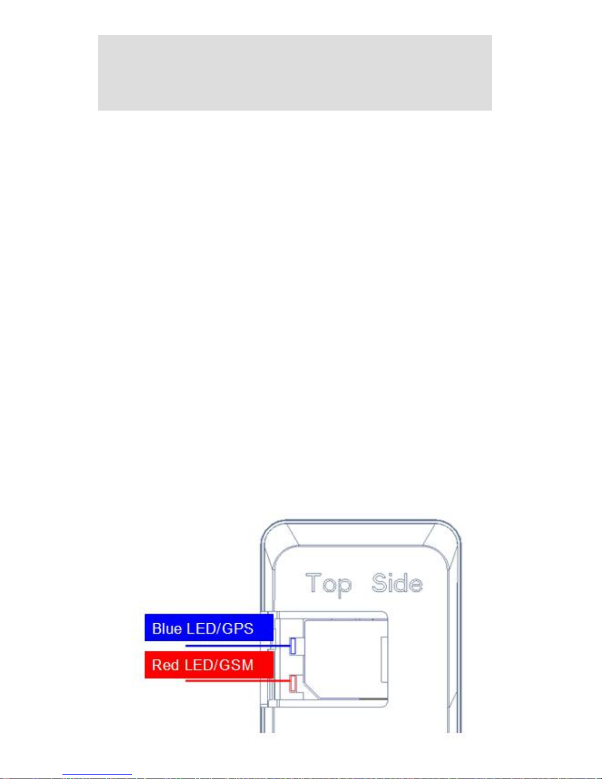
5.2 LED Indicators
The red LED flickers fast when terminal is
searching for GSM network, it flickers intermittently
when terminal has registered GSM network
successfully.
The blue LED flickers fast when terminal is
searching for the GPS satellite signal, it flickers
intermittently when terminal when terminal has
searched the satellites and can be positioned.
Page 16
16
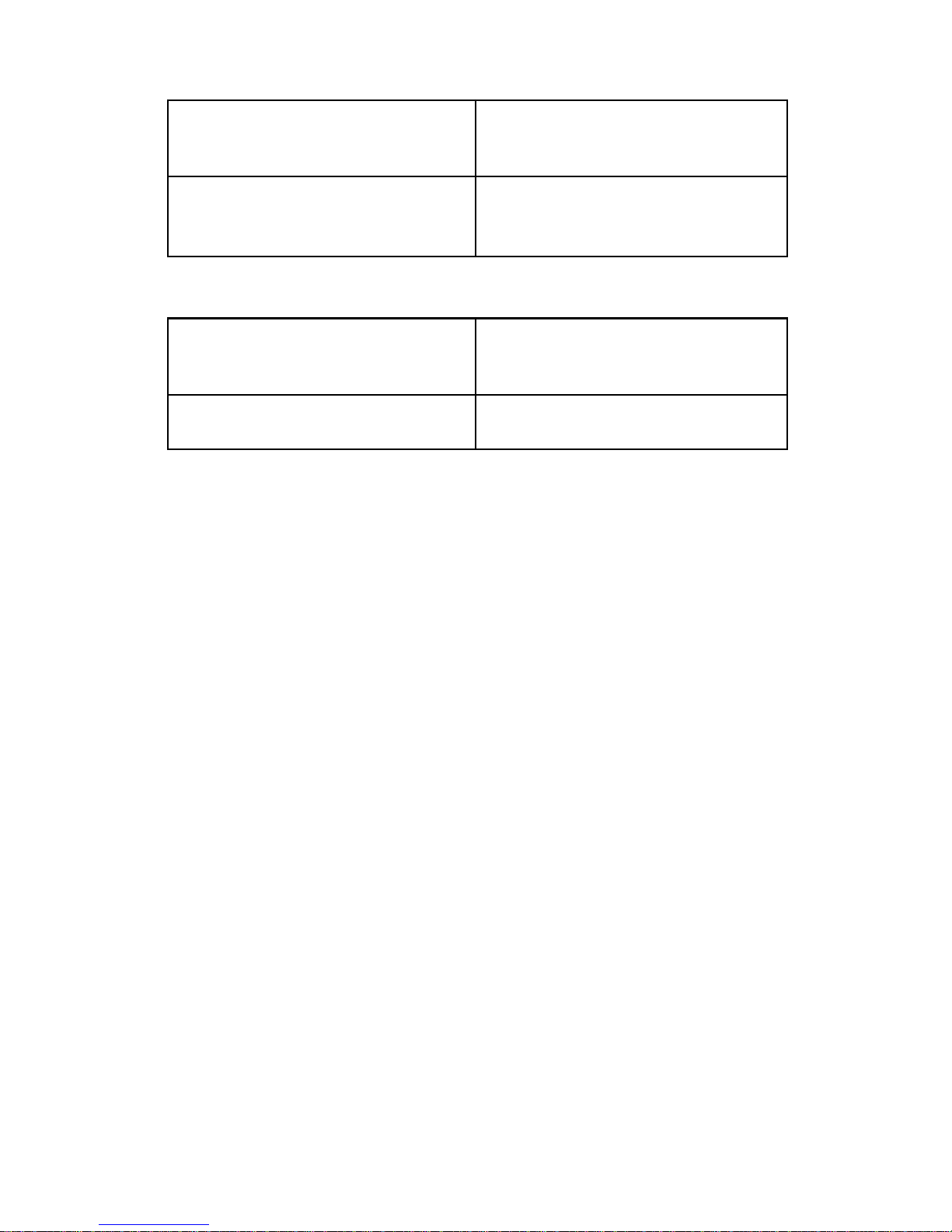
1. Red LED(indicates GSM working state)
fast flicker
Searching for GSM
network
intermittently flicker
GSM/GPRS works
normally
2. Blue LED(indicates GPS signal state)
fast flicker
Searching GPS
Satellites
intermittently flicker
GPS works normally
Ⅵ. Inquiry/Monitoring/Cut Oil
6.1 Inquiry by SMS
You can write a positioning SMS sending to terminal
to inquiry terminal position, terminal will reply
position SMS or map link. The SMS commands
please refer to the Operation Commands
6.2 Inquiry by service platform
6.2.1 Web platform
You can login the service platform and Register &
enter your ID and password to check the position of
your terminal. Ask your dealer about the URL of
Web platform.
6.2.2 Smart phone APP
You can use a smart phone to check terminal’s
Page 17

17
position.We have prepare for you the Android client
(Android), Apple clients (IOS), please check with
your dealer to get installation package.
6.3 Cut off/Recover Oil circuits
6.3.1 Cut off oil circuits
Server(GPRS) or Center number (SMS)can send
cut-off fuel commands when needed. The fuel of the
vehicle will be cut off on the premise of safety.
To make sure the safety of vehicle, the fuel of the
vehicle will be cut off only if terminal has positioned
by GPS and the speed of the vehicle is less than
20KM/h or the vehicle is not moving.
6.3.2 Recover oil circuits
Server(GPRS) or Center number (SMS) can send
recover-fuel-circuit commands to terminal when
needed, terminal will recover fuel circuits of vehicle.
Ⅶ. Set up terminal
Please refer to the《Operation Commands》
Ⅷ. Terminal Alarm
8.1 Vibration Alarm(only B type)
Conditions: There is a Vehicle Vibration.
Page 18

18
Note: You need to set vibration sensitivity and time,
there are arm / disarm switch.
8.2 Collision / Falling Alarm(only B
type)
Conditions: There is a Vehicle Collision or it’s falling
down.
8.3 Speed Alarm
Conditions: When the vehicle over and below the
set speed.
Note: You need to set the low speed limit and high
speed limit.
8.4 Geo-fence Alarm
Conditions: when the vehicle entry / exit / across
the Geo-fence.
Note: You need to set the conditions of crossing
fence, fence types and so on.
Note: When above alarm occurs,terminal will send
alarm to service platform, meanwhile send a SMS
message to the device administrator number if the
number is set up.
Note: 8.1 and 8.2 is the alarm for B type(add
acceleration sensor component); 8.3 and 8.4 alarm
parameters must be set before work, Please refer
to the《Operation Commands》
Page 19

19
Ⅸ. Trouble shooting
9.1 Cannot connect to the platform
terminal is never online on the position server when
installed at the first time. Please check terminal:
1)If the power cables are wired correctly? Pay
attention to not connect them to the controlling
cables of the vehicle.
2)If the SIM card is installed correctly? Please refer
to the installation instructions.
3)Check the status of the LED indicators. If
terminal is OK, the red LED and the blue LED will
intermittently flick.
4)Inquiry the parameters of terminal via commands
and check the accuracy of the parameters.
9.2 Offline status on the platform
First check if the LED indicators are OK, if cannot
check them, you can check the SIM card following
next steps:
1)call the SIM card of terminal and check if you can
hear the connecting ring.
Page 20

20
2)Check if the vehicle is in the area where there is
no GSM signal.
3)Check if one terminal or all terminals are offline
in the area where terminal is offline. If all terminals
are offline, you should ask the network operator If
the network is OK.
4)Check if the SIM card has enough balance.
5)If terminal becomes offline on the last day of one
month, please check GPRS is closed or not.
6)Inquiry the parameters of terminal via commands
and check the accuracy of the parameters.
9.3 Not positioning for a long time
If the GPS is active, but terminal cannot be
positioned for long time, please check terminal:
1)Check If vehicle is in the place where there is no
GPS signal.
2)The upside of terminal should be installed with
face toward the sky.
3)The GSM and GPS signal may be weakened if
terminal is installed in the place with
electromagnetic wave absorption material(such as
Page 21

21
metal blocks), special attention should be paid if
there is metal thermal insulation layer or heating
layer on the front windshield, so that the position
accuracy will decline, and the severe ones will not
be positioned.
9.4 Position drift is serious
Serious position drift will be found in places where
GPS signal is poor. Please drive the vehicle to the
open places.
9.5 Commands receiving abnormally
1)Check the commands format.
2)Check if the vehicle is in the places where there
is GSM signal.
3)Check if the SIM card is properly installed.
Ⅹ. Warranty Rules
10.1 Special statement
1)Technology change without notice.
2) If the color and appearance are inconsistent with
those for the actual product, Please according to
the actual device received.
Page 22

22
3)Warranty card is only valid for terminals with the
following IMEI.
4)Please take care of the warranty card and show
it with the original purchase receipts when enjoying
the warranty service.
10.2 Warranty period
One year warranty from the purchase date if it
is not artificially damaged.
10.3 After sales
Any of the following circumstances not
covered by the warranty, but may be
appropriate to pay repair:
1)More than the warranty period.
2)Unauthorized removal or repair damaged.
3)Damage caused by improper installation, use,
maintenance, custody.
4)The IMEI label is torn or Obscure.
5)Warranty certificate and product models do not
match or warranty certificate be altered.
6)Damage caused by force majeure.
Page 23

23
Warranty Card
NAME
TEL
Address
Model
IMEI Number
Selling Unit
Purchase Date
YY MM DD
Page 24

24
Maintenance Records
Engineer
Completion Date
Records
Description
Date
 Loading...