

Eelectron VS00ExxKNX User Manual
VS00E01KNXFI01010007.DOC
Eelecta® Touch Panel 3,5 KNX – Product Handbook
1/156
Eelectron SpA, Via Magenta 77/22, I-20017 Rho (MI), Italia
+39 02.9316681 +39 02.93507688
info@eelectron.com www.eelectron.com
VS00E01KNXFI01010007.doc
C.F. e P.IVA 11666760159
Capitale sociale: 250.000,00€ interamente versato
Tribunale di Milano 359157-8760-07
CCIAA Milano 148549
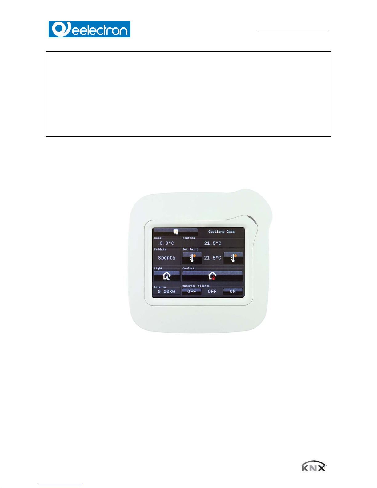
Touch Panel 3,5 KNX
VS00ExxKNX
Product Handbook
Product: Touch Panel 3,5 KNX
Order Code: VS00ExxKNX

VS00E01KNXFI01010007.DOC
Eelecta® Touch Panel 3,5 KNX – Product Handbook
2/156
Eelectron SpA, Via Magenta 77/22, I-20017 Rho (MI), Italia
+39 02.9316681 +39 02.93507688
info@eelectron.com www.eelectron.com
VS00E01KNXFI01010007.doc
C.F. e P.IVA 11666760159
Capitale sociale: 250.000,00€ interamente versato
Tribunale di Milano 359157-8760-07
CCIAA Milano 148549
INDEX
1. Application description .................................................................................................... 8
1.1 Main ................................................................................................................................ 8
1.2 Master password ............................................................................................................ 8
1.3 Main Format String and Additional Parameters .............................................................. 9
1.4 OBJ194OUT ................................................................................................................... 9
1.5 OBJ194IN ....................................................................................................................... 9
1.6 Pages ............................................................................................................................ 10
1.7 Use Password for Settings Dialog: ............................................................................... 10
1.8 Page 1-5 Name; Format: .............................................................................................. 10
1.9 Use Password for Pages 2-5 ........................................................................................ 10
1.10 Page 6 (Alarm) Name; Format ................................................................................. 10
1.11 Using Logic Functions: ............................................................................................. 10
1.12 Using Temperature Control: ..................................................................................... 10
1.13 ETS Objects ............................................................................................................. 10
2. Product Page ................................................................................................................ 11
2.1 Installation ..................................................................................................................... 11
2.2 Technical data .............................................................................................................. 12
2.3 Commissioning ............................................................................................................. 13
2.4 Behaviour at bus voltage recovery: .............................................................................. 13
2.5 Discharging program and resetting device: .................................................................. 13
2.6 Arrangement of the control elements ............................................................................ 13
3. Description of the control elements .............................................................................. 15
3.1 Selecting and presetting control elements .................................................................... 15
4.
Overview 1bit Elements ................................................................................................ 16
4.1 1-bit-ON/OFF-Toggle-Text ............................................................................................ 17
4.2 1-bit-ON/OFF-Toggle-Picture ....................................................................................... 18
4.3 1-bit-ON/OFF-Toggle-Text with Value .......................................................................... 19
4.4 1-bit-ON/OFF-Toggle-Picture with Value ...................................................................... 20
4.5 1-bit-ON/OFF-Text with Value ...................................................................................... 21
4.6 1-bit-ON/OFF-Picture with Value .................................................................................. 22
4.7 1-Bit-Value-Pushbutton ................................................................................................. 23
4.8 1-Bit-Timer-Profile ......................................................................................................... 24
4.9 1-bit-Quad-ON/OFF-Status/Toggle-Text ...................................................................... 26
4.10 1-bit-Quad-ON/OFF-Status/Toggle-Picture .............................................................. 27
4.11 . 1-bit-Quad-Value-Pushbutton-Text ........................................................................ 28
4.12 1-bit-Quad-Value-Pushbutton-Picture ...................................................................... 29
5. Overview 1Byte Elements ............................................................................................. 30
5.1 1-Byte-Value-Text-Button 0..255 .................................................................................. 32
5.2 1-Byte-Value-Picture-Button 0..255 .............................................................................. 33
5.3 1-Byte-Value-Slider 0..255 ............................................................................................ 34
5.4 1-Byte-Value-Text-Button -128..127 ............................................................................. 35
5.5 1-Byte-Value-Picture-Button -128..127 ......................................................................... 36
5.6 1-Byte-Value-Slider -128..127 ...................................................................................... 37
5.7 1-Byte-Value-Text-Button 0..100% ............................................................................... 38
5.8 1-Byte-Value-Picture-Button 0..100% ........................................................................... 39
5.9 1-Byte-Value-Slider 0..100% ........................................................................................ 40
5.10 1-Byte-Value-Text-Button 0..360° ............................................................................ 41
5.11 1-Byte-Value-Picture-Button 0..360° ........................................................................ 42
5.12 1-Byte-Value-Slider 0..360° ...................................................................................... 43

VS00E01KNXFI01010007.DOC
Eelecta® Touch Panel 3,5 KNX – Product Handbook
3/156
Eelectron SpA, Via Magenta 77/22, I-20017 Rho (MI), Italia
+39 02.9316681 +39 02.93507688
info@eelectron.com www.eelectron.com
VS00E01KNXFI01010007.doc
C.F. e P.IVA 11666760159
Capitale sociale: 250.000,00€ interamente versato
Tribunale di Milano 359157-8760-07
CCIAA Milano 148549
5.13 1-Byte-Value-Pushbutton ......................................................................................... 44
5.14 1-Byte-Timer-Profile 0..100% ................................................................................... 45
5.15 1-Byte-Timer-Profile 0..255 ...................................................................................... 46
5.16 1-Byte-Quad-Value/Change 0..255 .......................................................................... 48
5.17 1-Byte-Quad-Value/Change -128..127 ..................................................................... 48
5.18 1-Byte-Quad-Value/Change 0..100% ....................................................................... 49
5.19 1-Byte-Quad-Value/Change 0..360° ........................................................................ 49
6. Overview 2Byte Elements ............................................................................................. 50
6.1. 2-Byte-Value-Text-Button 0..65535 .......................................................................... 52
6.2. 2-Byte-Value-Picture-Button 0..65535 ..................................................................... 53
6.3. 2-Byte-Value-Slider 0..65535 ................................................................................... 54
6.4. 2-Byte-Value-Text-Button -32768..32767 ................................................................ 55
6.5. 2-Byte-Value-Picture-Button -32768..32767 ............................................................ 56
6.6. 2-Byte-Value-Slider -32768..32767 .......................................................................... 57
6.7. 2-Byte-Float-Text-Button .......................................................................................... 58
6.8. 2-Byte-Float-Picture-Button ...................................................................................... 59
6.9. 2-Byte-Float-Slider ................................................................................................... 60
6.10. 2-Byte-Value-Pushbutton ......................................................................................... 61
6.11. 2-Byte-Float-Value-Pushbtton .................................................................................. 62
6.12. 2-Byte-Float-Timer-Profile ........................................................................................ 63
7. Overview Time/Date Elements ..................................................................................... 64
7.1. 3-Byte-Time .............................................................................................................. 64
7.2. 3-Byte-Date .............................................................................................................. 65
7.3. Alarmclock
................................................................................................................ 66
7.4. Alarmtimer ................................................................................................................ 67
8. Overview 4Byte Elements ............................................................................................. 68
8.1. 4-Byte-Float-Text-Button .......................................................................................... 69
8.2. 4-Byte-Float-Picture-Button ...................................................................................... 70
8.3. 4-Byte-Float-Slider ................................................................................................... 71
8.4. 4-Byte-Value-Pushbutton ......................................................................................... 72
8.5. 4-Byte-Float-Value-Pushbutton ................................................................................ 73
9. Overview 14Byte Elements ........................................................................................... 74
9.1. 14-Byte-String-Pushbutton ....................................................................................... 75
9.2. 14-Byte-String .......................................................................................................... 76
10. Overview Scene Elements ............................................................................................ 77
10.1. Scene-Control-Recall-Save (Until FW version 2.15) ................................................ 78
10.2. Scene-Control-Recall-Save (From FW version 2.16) ............................................... 79
10.3. Scene-Control-Recall-Only (Until FW version 2.15) ................................................. 80
10.4. Scene-Control-Recall-Only (From FW version 2.16) ............................................... 81
10.5. Scene-Control-Save-Only (Until FW version 2.15) .................................................. 82
10.6. Scene-Control-Save-Only (From FW version 2.16) ................................................. 83
11. Overview RGB Elements .............................................................................................. 84
11.1. RGB-Dimmer-A ........................................................................................................ 85
11.2. RGB-Dimmer-B ........................................................................................................ 86
11.3. RGB-Dimmer-C ........................................................................................................ 87
11.4. RGB-Dimmer-D ........................................................................................................ 88
12. Overview Dimmer Elements ......................................................................................... 89
12.1.
4-Bit-Dimmer-Start-Stop ........................................................................................... 90
12.2. 4-Bit-Dimmer-Repeat ............................................................................................... 91
12.3. 8-Bit-Dimmer-Repeat ............................................................................................... 92

VS00E01KNXFI01010007.DOC
Eelecta® Touch Panel 3,5 KNX – Product Handbook
4/156
Eelectron SpA, Via Magenta 77/22, I-20017 Rho (MI), Italia
+39 02.9316681 +39 02.93507688
info@eelectron.com www.eelectron.com
VS00E01KNXFI01010007.doc
C.F. e P.IVA 11666760159
Capitale sociale: 250.000,00€ interamente versato
Tribunale di Milano 359157-8760-07
CCIAA Milano 148549
13. Overview Shutter-Blinds Elements ............................................................................... 93
13.1. Shutter-Blinds-Control-A .......................................................................................... 94
13.2. Shutter-Blinds-Control-B .......................................................................................... 95
13.3. Shutter-Blinds-Control-C .......................................................................................... 96
14. Overview HVAC Elements ............................................................................................ 97
14.1. HVAC Setpoint-Control ............................................................................................ 98
14.2. HVAC Mode-Control ................................................................................................ 99
14.3. HVAC Mode-Control-Text ...................................................................................... 100
14.4. 1-Byte-Timer-Profile HVAC .................................................................................... 101
15. System settings .......................................................................................................... 102
15.1. Main ....................................................................................................................... 102
15.2. Time & date ............................................................................................................ 103
15.3. Standby .................................................................................................................. 103
15.4. Audio signals .......................................................................................................... 104
15.5. Fonts ...................................................................................................................... 104
15.6. System & SD card .................................................................................................. 105
15.7. Layouts & language ............................................................................................... 106
16. Screensaver ................................................................................................................ 107
16.1. ETS ........................................................................................................................ 107
16.2. Parameter setting ................................................................................................... 107
17. RTC General Information ............................................................................................ 109
17.1. Structure of this section .......................................................................................... 109
17.2. How to read this ..................................................................................................... 109
17.3. Overview ................................................................................................................ 111
17.4. Important ................................................................................................................ 112
17.5. Device-internal communication to control the RTC ................................................ 112
17.6. PI-Controller set up ................................................................................................ 112
17.6.1. Adjusting the PI Controller: ................................................................................ 112
17.6.2. General basic rules:........................................................................................... 113
17.6.3. Setpoint handling ............................................................................................... 113
17.6.4. Setpoint adjustment ........................................................................................... 113
17.6.5. Absolute vs. relative setpoint ............................................................................. 113
17.6.6. Heating/Cooling gap .......................................................................................... 113
17.6.7. Illustrated Examples .......................................................................................... 114
17.7. Room temperature controllers ................................................................................ 116
17.7.1. Heating vs. Cooling controller ............................................................................ 116
17.7.2. One- vs. Two-stage controllers .......................................................................... 116
17.7.3. Heating/Cooling switched vs. gap controller ...................................................... 117
17.7.4. 2 vs. 4-Pipes Fancoil ......................................................................................... 119
17.7.5. Switched vs. gap fancoil controller .................................................................... 119
17.7.6. Controller output objects.................................................................................... 119
18. RTC Parameter ........................................................................................................... 121
18.1. 1st/2nd stage bandgap (Temp. Controller Heating/Cooling) .................................. 121
18.2. 3-point bandgap (Temp. Controller Heating/Cooling) ............................................ 121
18.3. Absolute/relative setpoints (Temp. controller Settings) .......................................... 122
18.4. Relative .................................................................................................................. 122
18.5. Absolute ................................................................................................................. 122
18.6. Comfort setpoint temperature (absolute) (Temp. Controller Settings) ................... 122
18.7. Controller Fan Limit 1 [%] (Controller Page Fan) ................................................... 122
18.8. Controller Fan Limit 2 [%] (Controller Page Fan) ................................................... 123

VS00E01KNXFI01010007.DOC
Eelecta® Touch Panel 3,5 KNX – Product Handbook
5/156
Eelectron SpA, Via Magenta 77/22, I-20017 Rho (MI), Italia
+39 02.9316681 +39 02.93507688
info@eelectron.com www.eelectron.com
VS00E01KNXFI01010007.doc
C.F. e P.IVA 11666760159
Capitale sociale: 250.000,00€ interamente versato
Tribunale di Milano 359157-8760-07
CCIAA Milano 148549
18.9. Controller Fan Limit 3 [%] (Controller Page Fan) ................................................... 123
18.10. Controller Fan Proportional Part (Controller Page Fan) ......................................... 124
18.11. Controller proportional band style (Temp. Controller Settings) .............................. 124
18.12. Symmetric to setpoint ............................................................................................. 124
18.13. Asymmetric to setpoint ........................................................................................... 125
18.14. Controller type (Temp. Controller Heating/Cooling) ............................................... 125
18.14.1. 2-point controller ................................................................................................ 126
18.14.2. 3-point controller ................................................................................................ 126
18.14.3. PI-controller ....................................................................................................... 127
18.14.4. PI-controller with PWM ...................................................................................... 127
18.15. Economy setpoint temperature (absolute) (Temp. Contr. Settings) ....................... 128
18.16. Economy setpoint temperature (heating, absolute) (Temp. Contr. Settings) ......... 128
18.17. Economy setpoint temperature decrease (Temp. Contr. Settings) ........................ 128
18.18. Economy setpoint temperature increase (Temp. Contr. Settings) ......................... 128
18.19. Economy setpoint temperature de-/increase (Temp. Contr. Settings) ................... 128
18.20. External temperature weight [ % ] (Temp. Controller Settings) .............................. 128
18.21. Fan lag-time [sec] (Controller Page Fan) ............................................................... 129
18.22. Fan Lead-time [sec] (Controller Page Fan) ............................................................ 129
18.23. Fan Steadyoutput Stepwidth [%] (Controller Page Fan) ........................................ 129
18.24. Heating/cooling bandgap (Temp. Controller Settings) ........................................... 129
18.25. Heating/cooling changeover deadtime (Temp. Contr. Settings) ............................ 130
18.26. Hysteresis (Temp. Controller Heating/Cooling) ...................................................... 130
18.27. Integration time [ minutes ] (Temp. Controller Heating/Cooling) ............................ 130
18.28. Minimum/maximum gap [ % ] (Temp. Controller Heating/Cooling) ........................ 130
18.29. Output send on change off (Temp. Controller Heating/Cooling) ............................ 131
18.30. Outputs sending cycle [ minutes ] (Temp. Controller Settings) .............................. 131
18.31. Overwrite timeout [ minutes ] (Temp. Controller Settings) ..................................... 131
18.32. Proportional band (Temp. Controller Heating/Cooling] .......................................... 132
18.33. Protection setpoint temperature high (absolute) [ °C ] (Temp. Controller Settings) 132
18.34. Protection setpoint temperature low (absolute) [ °C ] (Temp. Controller Settings) 132
18.35. PWM cycletime [ seconds ] ( *10 ) (Temp. Contr. Heating/Cooling) ...................... 132
18.36. Setpoint adjustment range (Temp. Controller Settings) ......................................... 133
18.37. Stand-by setpoint temperature (absolute) (Temp. Contr. Settings) ....................... 134
18.38. Stand-By setpoint temperature (heating, absolute) (Temp. Contr. Settings) ......... 134
18.39. Stand-by setpoint temperature de-/increase (Temp .Controller Settings) .............. 134
18.40. Stand-By setpoint temperature decrease (Temp. Controller Settings) .................. 134
18.41. Standby setpoint temperature increase (Temp. Controller Settings) ..................... 134
18.42. Steady-output value (Controller Page Fan) ............................................................ 134
18.43. Temperature offset [ * 0,1 °C ] (Temp. Controller Settings) ................................... 135
18.44. Temperature send cycle [ minutes ] (Temp. Controller Settings) ........................... 135
18.45. Temperature send on change of (Temp. Controller Settings) ................................ 135
19. RTC Communication Objects ..................................................................................... 136
19.1. Output, actual Temperature [196] .......................................................................... 136
19.2. Input, external Temperature [197] .......................................................................... 136
19.3. Input, HVAC-Mode [198] ........................................................................................ 136
19.4. Input, Setpoint Comfort Mode ( absolute ) [199] .................................................... 137
19.5. Input, Setpoint Economy Mode decrease [200] ..................................................... 137
19.6. Input, Setpoint Standby Mode decrease [201] ....................................................... 137
19.7. Input, Set Protection Mode [202] ............................................................................ 137
19.8.
Input, Set Comfort Mode (overwrite) [203] ............................................................. 137

VS00E01KNXFI01010007.DOC
Eelecta® Touch Panel 3,5 KNX – Product Handbook
6/156
Eelectron SpA, Via Magenta 77/22, I-20017 Rho (MI), Italia
+39 02.9316681 +39 02.93507688
info@eelectron.com www.eelectron.com
VS00E01KNXFI01010007.doc
C.F. e P.IVA 11666760159
Capitale sociale: 250.000,00€ interamente versato
Tribunale di Milano 359157-8760-07
CCIAA Milano 148549
19.9. Input, Set Comfort Mode [204] ............................................................................... 137
19.10. Input, Set Economy Mode [205] ............................................................................. 137
19.11. Input, Set OFF Mode [206] ..................................................................................... 138
19.12. Input, Setpoint Adjust [207] .................................................................................... 138
19.13. Output, Setpoint [208] ............................................................................................ 138
19.14. Input, Setpoint Economy Mode ( absolute ) [200] .................................................. 138
19.15. Input, Setpoint Economy Mode ( heating, absolute ) [200] .................................... 138
19.16. Input, Setpoint Economy Mode de-/increase [200] ................................................ 138
19.17. Input, Setpoint Economy Mode increase [200] ...................................................... 139
19.18. Input, Setpoint Standby Mode ( absolute ) [201] .................................................... 139
19.19. Input, Setpoint Standby Mode ( heating, absolute ) [201] ...................................... 139
19.20. Input, Setpoint Standby Mode de-/increase [201] .................................................. 139
19.21. Input, Setpoint Standby Mode increase [201] ........................................................ 139
19.22. Input, Heating/Cooling [219] ................................................................................... 139
19.23. Output, Heating/Cooling [219] ................................................................................ 139
19.24. Output, Heating/Cooling, 1st Level Switch [210/214] ............................................. 140
19.25. Output, Heating/Cooling, 2nd Level Switch [212/216] ............................................ 140
19.26. Output, Heating/Cooling, PWM Output [210/214] .................................................. 140
19.27. Output, Heating/Cooling, Steady Output [209/213] ................................................ 140
19.28. Output, Heating/Cooling, Steady Output non-zero [210/214] ................................. 140
19.29. Output, Heating/Cooling, Switch [210/214] ............................................................ 140
19.30. Output, Cooling 1st Stage, 1st Level Switch [214] ................................................. 140
19.31. Output, Cooling 1st Stage, 2nd Level Switch [216] ................................................ 140
19.32. Output, Cooling 1st Stage, PWM Output [214] ...................................................... 140
19.33.
Output, Cooling 1st Stage, Steady Output [213] .................................................... 140
19.34. Output, Cooling 1st Stage, Steady Output non-zero [214] ..................................... 141
19.35. Output, Cooling 1st Stage, Switch [214] ................................................................ 141
19.36. Output, Cooling 2nd Stage, 1st Level Switch [214] ................................................ 141
19.37. Output, Cooling 2nd Stage, 2nd Level Switch [216] ............................................... 141
19.38. Output, Cooling 2nd Stage, PWM Output [216] ..................................................... 141
19.39. Output, Cooling 2nd Stage, Steady Output [215] ................................................... 141
19.40. Output, Cooling 2nd Stage, Steady Output non-zero [216] .................................... 141
19.41. Output, Cooling 2nd Stage, Switch [216] ............................................................... 141
19.42. Output, Cooling, 1st Level Switch [213] ................................................................. 141
19.43. Output, Cooling, 2nd Level Switch [214] ................................................................ 141
19.44. Output, Cooling, PWM Output [214] ....................................................................... 141
19.45. Output, Cooling, Steady Output [216] .................................................................... 142
19.46. Output, Cooling, Steady Output non-zero [214] ..................................................... 142
19.47. Output, Cooling, Switch [214] ................................................................................. 142
19.48. Output, Heating 1st Stage, 1st Level Switch [209] ................................................. 142
19.49. Output, Heating 1st Stage, 2nd Level Switch [210] ................................................ 142
19.50. Output, Heating 1st Stage, PWM Output [210] ...................................................... 142
19.51. Output, Heating 1st Stage, Steady Ouptut non-zero [210] ..................................... 142
19.52. Output, Heating 1st Stage, Steady Output [209] .................................................... 142
19.53. Output, Heating 1st Stage, Switch [210] ................................................................ 142
19.54. Output, Heating 2nd Stage, 1st Level Switch [211] ................................................ 142
19.55. Output, Heating 2nd Stage, 2nd Level Switch [212] .............................................. 142
19.56. Output, Heating 2nd Stage, PWM Output [212] ..................................................... 143
19.57. Output, Heating 2nd Stage, Steady Output [211] ................................................... 143
19.58. Output, Heating 2nd Stage, Steady Output non-zero [212] ................................... 143

VS00E01KNXFI01010007.DOC
Eelecta® Touch Panel 3,5 KNX – Product Handbook
7/156
Eelectron SpA, Via Magenta 77/22, I-20017 Rho (MI), Italia
+39 02.9316681 +39 02.93507688
info@eelectron.com www.eelectron.com
VS00E01KNXFI01010007.doc
C.F. e P.IVA 11666760159
Capitale sociale: 250.000,00€ interamente versato
Tribunale di Milano 359157-8760-07
CCIAA Milano 148549
19.59. Output, Heating 2nd Stage, Switch [212] ............................................................... 143
19.60. Output, Heating, 1st Level Switch [209] ................................................................. 143
19.61. Output, Heating, 2nd Level Switch [210] ................................................................ 143
19.62. Output, Heating, PWM Output [210] ...................................................................... 143
19.63. Output, Heating, Steady Output [209] .................................................................... 143
19.64. Output, Heating, Steady Output non-zero [210] ..................................................... 143
19.65. Output, Heating, Switch [210] ................................................................................ 143
19.66. Output, Fan Continuous [%] [211] .......................................................................... 144
19.67. Output, Fan V1 [212] .............................................................................................. 144
19.68. Output, Fan V2 [215] .............................................................................................. 144
19.69. Output, Fan V3 [216] .............................................................................................. 144
19.70. Input, Fan Mode [217] ............................................................................................ 144
19.71. Input, Fan Speed [218] ........................................................................................... 145
19.72. Output, Status1 [220] ............................................................................................. 145
19.73. "Output, Status2" [221] ........................................................................................... 146
20. Logic ........................................................................................................................... 146
20.1. ETS ........................................................................................................................ 146
20.2. Functions ................................................................................................................ 147
20.2.1. KNX functions .................................................................................................... 147
20.2.2. System functions ............................................................................................... 148
20.2.3. Callback functions ............................................................................................. 148
20.2.4. Example applications ......................................................................................... 149
21. Custom Properties ...................................................................................................... 153
21.1. General .................................................................................................................. 153
21.2. Default set of icons ................................................................................................. 155
Any information inside this manual can be changed without advice.
This handbook can be download freely from the website: www.eelectron.com
Exclusion of liability:
Despite checking that the contents of this document match the hardware and software,
deviations cannot be completely excluded. We therefore cannot accept any liability for this.
Any necessary corrections will be incorporated into newer versions of this manual.
VS00E01KNXFI01010007.DOC
Eelecta® Touch Panel 3,5 KNX – Product Handbook
8/156
Eelectron SpA, Via Magenta 77/22, I-20017 Rho (MI), Italia
+39 02.9316681 +39 02.93507688
info@eelectron.com www.eelectron.com
VS00E01KNXFI01010007.doc
C.F. e P.IVA 11666760159
Capitale sociale: 250.000,00€ interamente versato
Tribunale di Milano 359157-8760-07
CCIAA Milano 148549
1. Application description
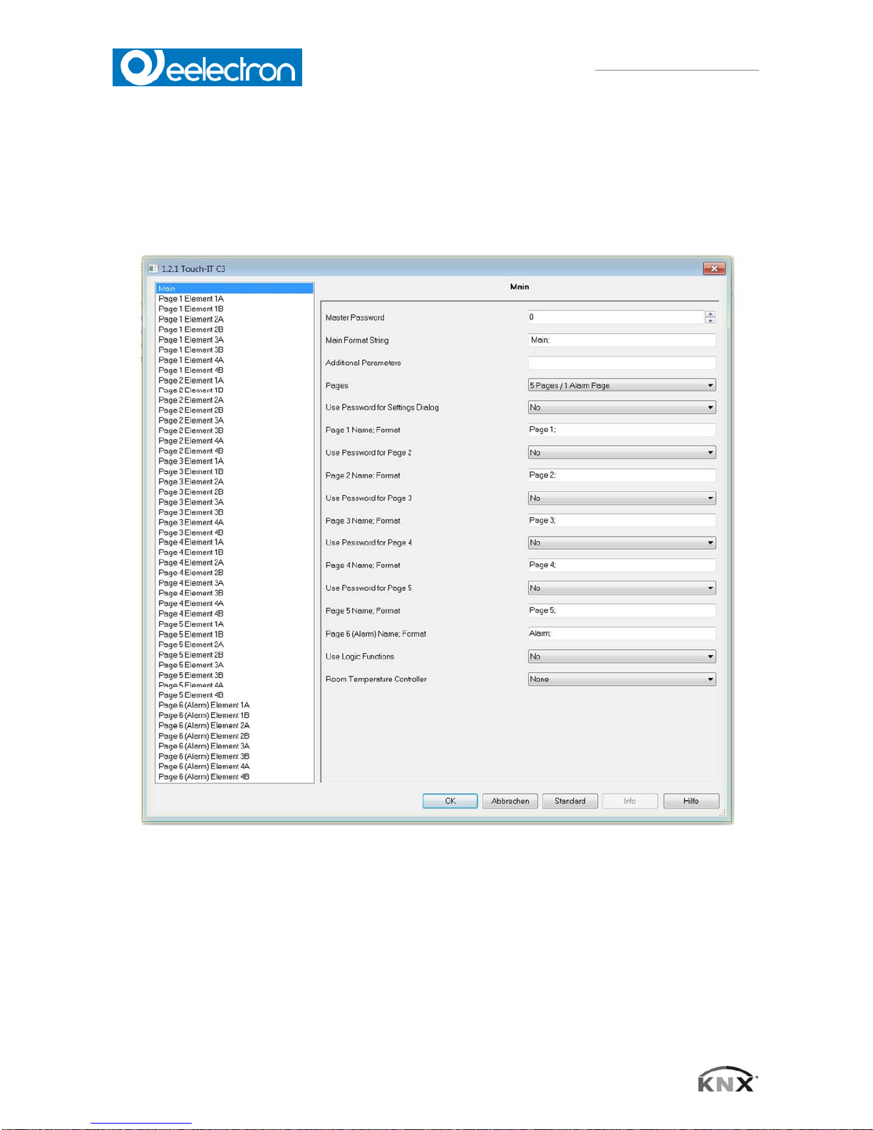
1.1 Main
1.2 Master password
A 4-digit password can be assigned to protect the different pages or object functions. In case that
the value is „0“, this function is inactive.
e.g. In case that the password is „1“, „0001“ must be entered on the Eelecta Touch Panel in
order to access the protected page or to execute a function of the protected element.
VS00E01KNXFI01010007.DOC
Eelecta® Touch Panel 3,5 KNX – Product Handbook
9/156
Eelectron SpA, Via Magenta 77/22, I-20017 Rho (MI), Italia
+39 02.9316681 +39 02.93507688
info@eelectron.com www.eelectron.com
VS00E01KNXFI01010007.doc
C.F. e P.IVA 11666760159
Capitale sociale: 250.000,00€ interamente versato
Tribunale di Milano 359157-8760-07
CCIAA Milano 148549
1.3 Main Format String and Additional Parameters
These fields are used for global parameter setting. The following parameters can be used:
TDSEND
No default value assigned. Date and time will not be sent.
TDSEND=xx
Time allowance for sending time and date. Specified in solid hours.
e.g. TDSEND=17 (Time and date will be sent every day at 5 pm)
STDLONG
Interpretation of a manual input as LONG (Default 500ms)
STDLONG=xx
Determines the time (in ms) from which the manual input will be taken as LONG.
STDREP
Default use of the general repetition rate. (Default 300ms)
STDREP=xx
Sets the repetition rate (in ms)
Two more parameters can be set in order to control standby object 194.
1.4 OBJ194OUT
This parameter determines how the output object reacts when the screen saver mode is changed.
Values can be sent when activating and leaving the screen saver. The following scheme
demonstrates the settings in dependency on the desired actions. Standby mode will be interpreted
as an extended screen saver mode.
Screensaver inactive Demonstration:
Standby object parameters are to be set as follows: „Send a 1 when
activating and a 0 when leaving the screen saver mode“. The
outcome of this is:
OBJ194OUT=WS;
Screen saver
(or standby )
active
0 1 x
0
-- SW Sx
1
WS -- xS
x
Wx xW --
1.5 OBJ194IN
Incoming telegrams on the system standby object can change the current status of the screen
saver. The changes can be defined for the values 0/1, as demonstrated in the following scheme.
Possible settings Demonstration:
The interpretation of an incoming telegram is
to be carried out as follows:
Change into standby mode at 0, and into
wake-up mode at 1
OBJ194IN=OW;
Input
xx Ox Sx Wx
0
-- Standby Screensaver Wake-Up
1
-- -- -- --
xO OO SO WO
0
-- Standby Screensaver Wake-Up
1
Standby Standby Standby Standby
xS OS SS WS
0
-- Standby Standby Wake-Up
1
Screensaver Screensaver Screensaver Screensaver
xW OW SW WW
0
-- Standby Screensaver Wake-Up
1
Wake-Up Wake-Up Wake-Up Wake-Up

VS00E01KNXFI01010007.DOC
Eelecta® Touch Panel 3,5 KNX – Product Handbook
10/156
Eelectron SpA, Via Magenta 77/22, I-20017 Rho (MI), Italia
+39 02.9316681 +39 02.93507688
info@eelectron.com www.eelectron.com
VS00E01KNXFI01010007.doc
C.F. e P.IVA 11666760159
Capitale sociale: 250.000,00€ interamente versato
Tribunale di Milano 359157-8760-07
CCIAA Milano 148549
1.6 Pages
There are two possible option:
5 control pages + 1 alarm page
control pages
1.7 Use Password for Settings Dialog:
Protect system page with a 4-digit password.
1.8 Page 1-5 Name; Format:
The names of the control pages that appear in the layout menu can be assigned here.
1.9 Use Password for Pages 2-5
Except for control page 1, all service pages can be protected/locked with a password.
(Exception: When 6 control pages are defined, page 6 cannot be protected with a password.)
1.10 Page 6 (Alarm) Name; Format
The name of the control or alarm page that appears in the layout menu can be assigned here.
In addition, global alarm settings can be set here.
RESCAN= Defines the time (in seconds) when alarm object is rescanned.
BEEPOFF= Number of acoustic alarm signals
AUTOHIDE = Leave alarm page if alarm condition is changed or confirmed in a different
point.
1.11 Using Logic Functions:
Further information on the logic functions is given in chapter 20 Logic.
1.12 Using Temperature Control:
Further information on the regulation of the room temperature is given in chapter 17 RTC General
Information.
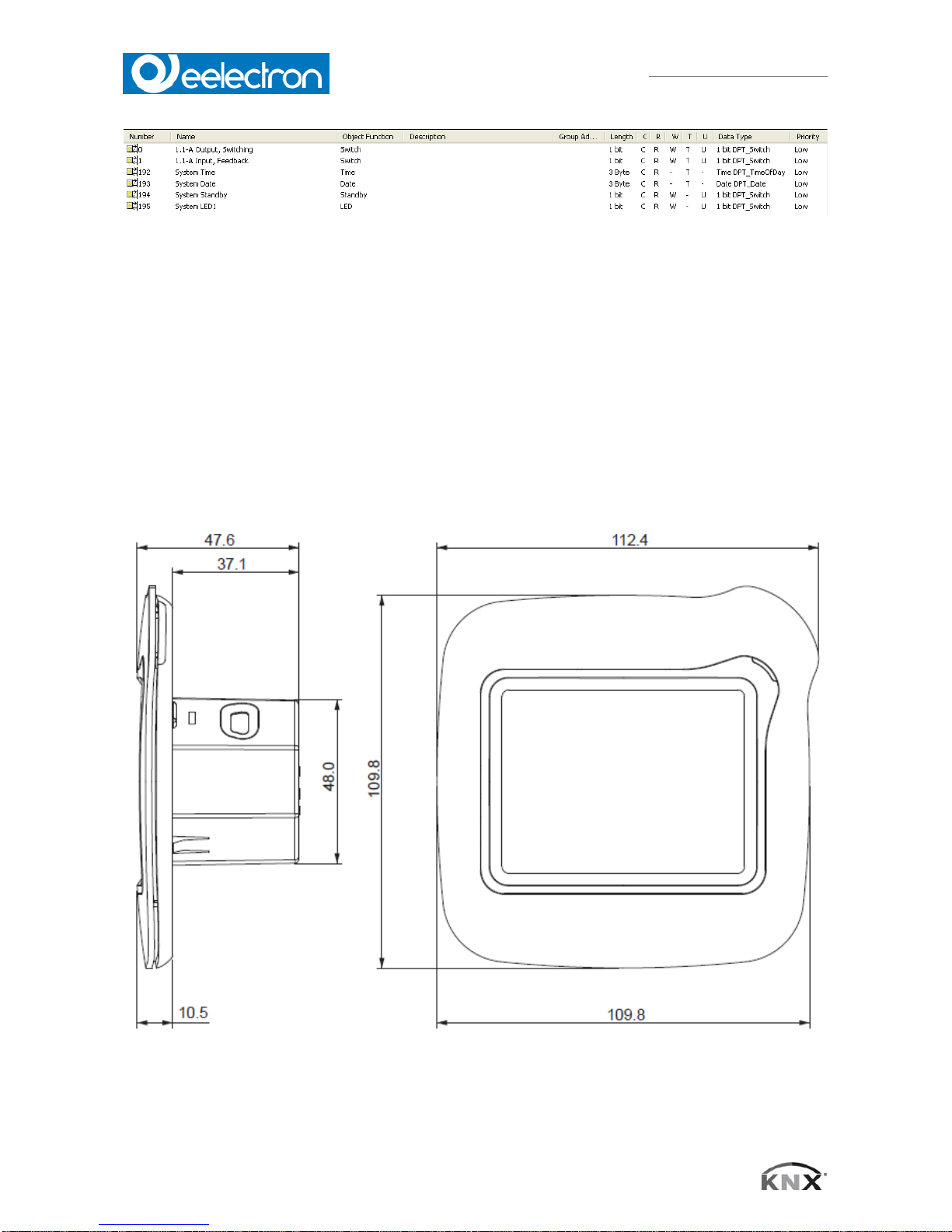
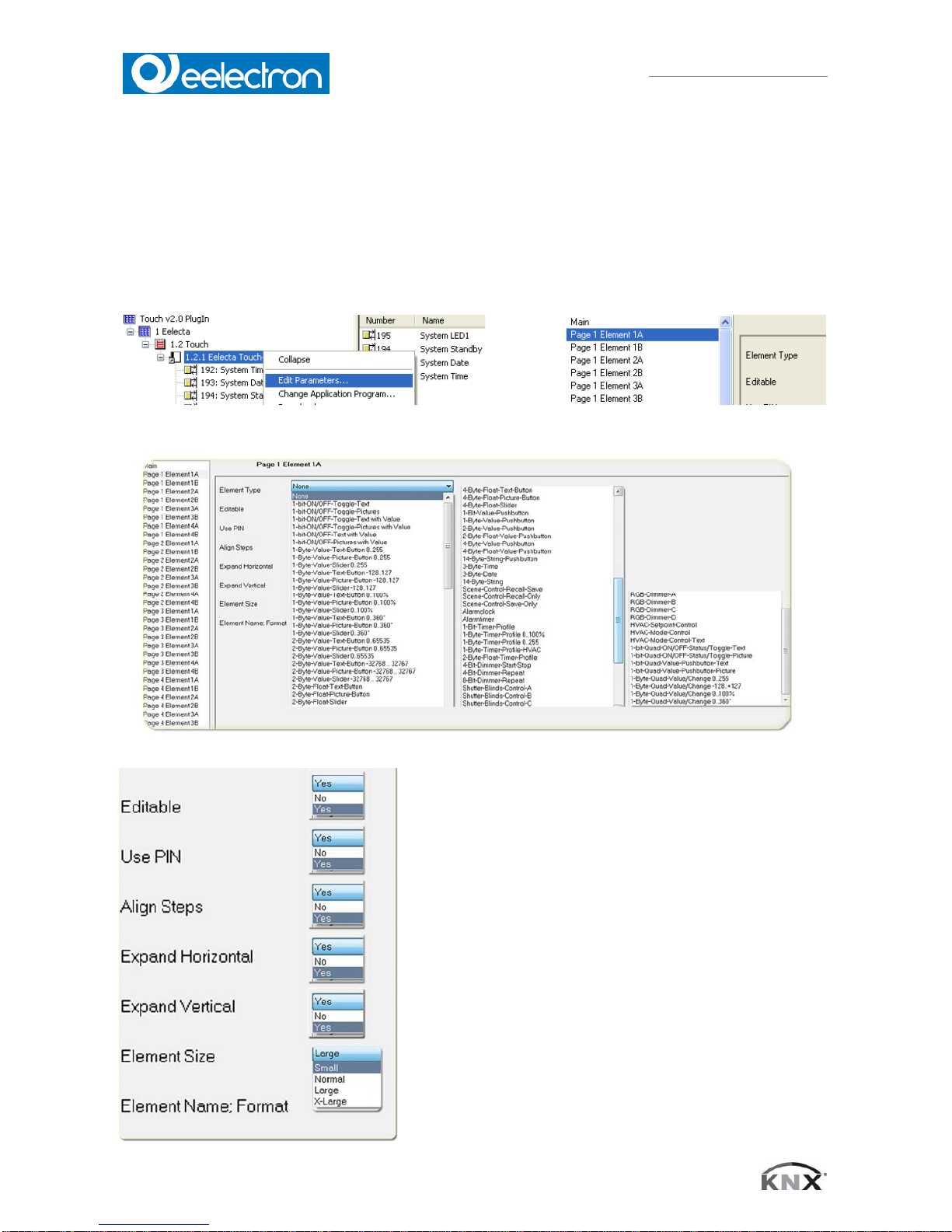
1.13 ETS Objects
Up to 196 group addressed can be administrated. If no elements are activated yet, only the system
objects within topology are displayed.
e.g. Element 1A is active on page 1 and defined as a 1-bit object. Topology will change as follows:
VS00E01KNXFI01010007.DOC
Eelecta® Touch Panel 3,5 KNX – Product Handbook
11/156
Eelectron SpA, Via Magenta 77/22, I-20017 Rho (MI), Italia
+39 02.9316681 +39 02.93507688
info@eelectron.com www.eelectron.com
VS00E01KNXFI01010007.doc
C.F. e P.IVA 11666760159
Capitale sociale: 250.000,00€ interamente versato
Tribunale di Milano 359157-8760-07
CCIAA Milano 148549
Every element includes function-specific objects that can be linked (Cf. chapter 3 Description of
the control elements). The exact analogy between parameter view and object view within
topology will be displayed as follows:
e.g. Page 3,element 2B equals 3.2-B within topology.
2. Product Page
2.1 Installation
3,5" display for visualization and control in a KNX bus, Installation is carried out using a mounting
ring.
VS00E01KNXFI01010007.DOC
Eelecta® Touch Panel 3,5 KNX – Product Handbook
12/156
Eelectron SpA, Via Magenta 77/22, I-20017 Rho (MI), Italia
+39 02.9316681 +39 02.93507688
info@eelectron.com www.eelectron.com
VS00E01KNXFI01010007.doc
C.F. e P.IVA 11666760159
Capitale sociale: 250.000,00€ interamente versato
Tribunale di Milano 359157-8760-07
CCIAA Milano 148549
Areas of application:
Switching and dimming of lights
Adjustment of color and brightness in RGB lights
Displaying switching states in a building
Operating blinds
Alarm functions, acoustic and optical
Alarm display of motion sensors with clear text
Displaying and setting heating adjustments
Displaying indoor and outdoor temperature
Weekly time switch
2.2 Technical data
Technical data Touch_IT C3
Display 3,5" TFT color display (320x240) (256k color) touch screen
Processor 200MHz 32 Bit ARM
Operating system Linux
Background Adjustable LED background light
Parameterization ETS
Max. Number of elements / Max. number of pages 8 / (5 control pages + 1 alarm page or 6 control pages)
Ambient temperature, storage (operation) -5 … +50°C (+45°C)
Operational voltage EIB/KNX bus voltage 21-32V DC
Approx. power consumption from KNX bus < 10 mA ( at 24V DC )
Auxiliary voltage DC 9-32 V, approx. 1.5 VA
Bus coupler integrated
Connections EIB-polar term.l (red/black); AUX-polar terminal (yell/white)
Degree of protection IP20
Installation type Installation with a metal frame adapter
Casing measurements 110 mm x 110 mm x 10 mm (W x H x D)
Article number:
VS00E11KNX 3,5" TOUCH PANEL KNX EELECTA - IVORY
VS00E20KNX 3,5" TOUCH PANEL KNX EELECTA - CHROMO
VS00E21KNX 3,5" TOUCH PANEL KNX EELECTA - CHROMO WITH BLACK FRAME
VS00E30KNX 3,5" TOUCH PANEL KNX EELECTA - BLACK MATTE
VS00E31KNX 3,5" TOUCH PANEL KNX EELECTA - BLACK MATTE - FRAME CHROMO
VS00E32KNX 3,5" TOUCH PANEL KNX EELECTA - BLACK WEAVE
VS00E40KNX 3,5" TOUCH PANEL KNX EELECTA - GOLD
VS00E50KNX 3,5" TOUCH PANEL KNX EELECTA - BRONZE

VS00E01KNXFI01010007.DOC
Eelecta® Touch Panel 3,5 KNX – Product Handbook
13/156
Eelectron SpA, Via Magenta 77/22, I-20017 Rho (MI), Italia
+39 02.9316681 +39 02.93507688
info@eelectron.com www.eelectron.com
VS00E01KNXFI01010007.doc
C.F. e P.IVA 11666760159
Capitale sociale: 250.000,00€ interamente versato
Tribunale di Milano 359157-8760-07
CCIAA Milano 148549
2.3 Commissioning
Commissioning the Eelecta Touch Panel is carried out using the ETS (EIB Tool Software) and the
corresponding application software. At delivery, the device is unprogrammed. All functions must be
parameterized and programmed using the ETS.
2.4 Behaviour at bus voltage recovery:
All settings carried out using the ETS will be preserved.
2.5 Discharging program and resetting device:
If the visualization does not react due to a malfunction or incorrect configuration of the
programming, the entire project work can be deleted by pressing the programming button. The
device will be reset to delivery status. Please hold the programming button while connecting power
supply and wait until the application for touch screen calibration appears. Normally, this takes 4060 seconds. After entering the 5 calibration points, you can download your application once again.
If the reset ex fabrica is performed all the default icons must be reload, to perform this operation
follow the instruction described in the document downloadable from eelectron website:
http://www.eelectron.com/download/120911042536_VS00E01KNXFI01020004.zip
And use the snapshot dowloadable from :
xxxxxxxxxxxxxxxxxxxxxxxxxxxxxx
2.6 Arrangement of the control elements
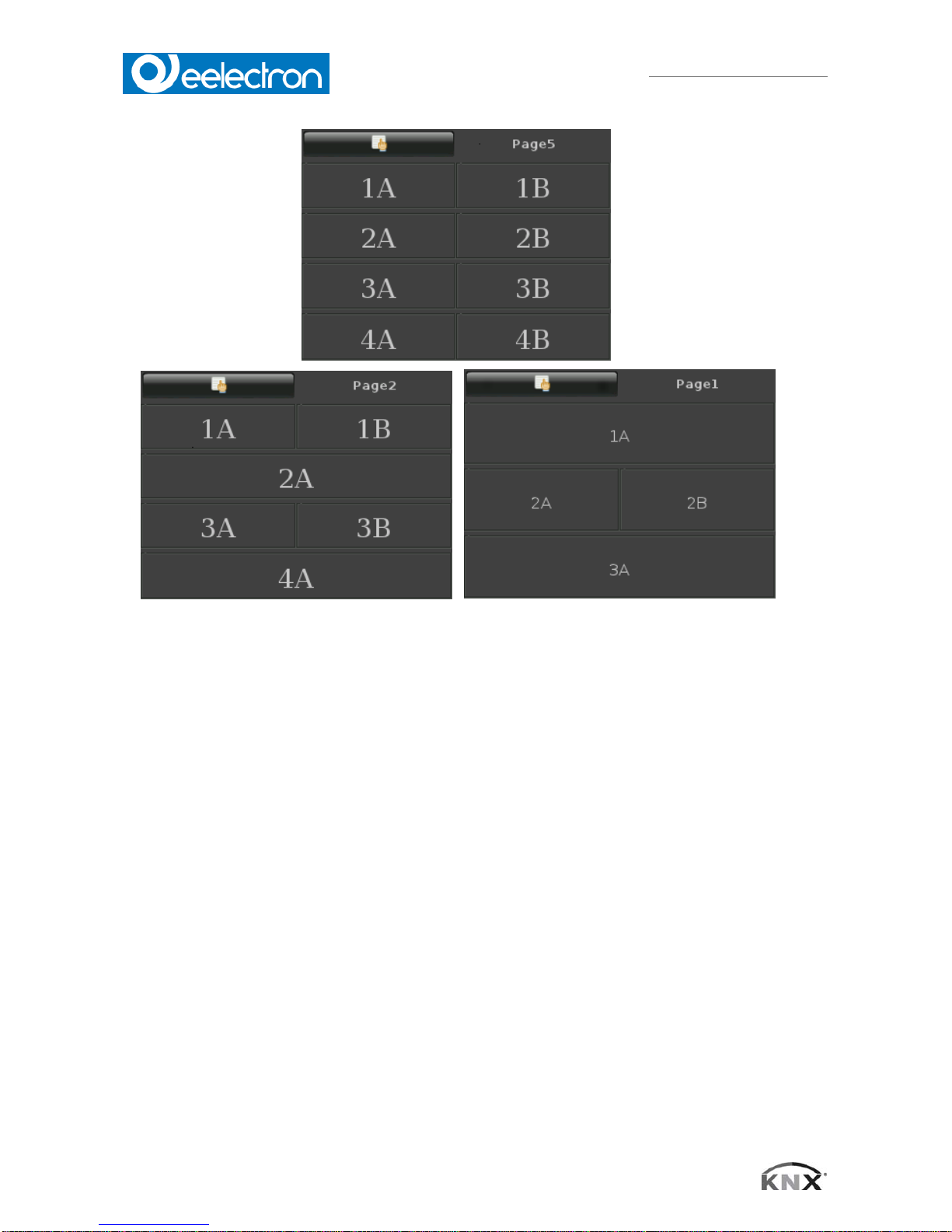
A maximum of 8 elements can be placed on each Eelecta Touch Panel page.
After uploading the parameters, the pages will be formatted automatically.
If there is a smaller number of elements on a page, they will be maximized to the available surface
VS00E01KNXFI01010007.DOC
Eelecta® Touch Panel 3,5 KNX – Product Handbook
14/156
Eelectron SpA, Via Magenta 77/22, I-20017 Rho (MI), Italia
+39 02.9316681 +39 02.93507688
info@eelectron.com www.eelectron.com
VS00E01KNXFI01010007.doc
C.F. e P.IVA 11666760159
Capitale sociale: 250.000,00€ interamente versato
Tribunale di Milano 359157-8760-07
CCIAA Milano 148549
(in case that the expand-settings (vertically and horizontally) are enabled).
VS00E01KNXFI01010007.DOC
Eelecta® Touch Panel 3,5 KNX – Product Handbook
15/156
Eelectron SpA, Via Magenta 77/22, I-20017 Rho (MI), Italia
+39 02.9316681 +39 02.93507688
info@eelectron.com www.eelectron.com
VS00E01KNXFI01010007.doc
C.F. e P.IVA 11666760159
Capitale sociale: 250.000,00€ interamente versato
Tribunale di Milano 359157-8760-07
CCIAA Milano 148549
3. Description of the control elements
3.1 Selecting and presetting control elements
The selection of control elements is carried out through a parameterization within the ETS.
Subsequently, various presets can be adjusted.
Editable
YES: Element is used as a display with a control element.
NO: Control element is solely used as a display.
Use Pin
Protect control element with a password.
Align Steps
Round value up or down to a multiple of the stepwidth.
Expand Horizontal
Maximize control element horizontally.
Expand Vertical
Maximize control element vertically.
Element Size
Determines, which element size is used.
There are 4 sizes available (Small, Normal, Large, X- Large).
VS00E01KNXFI01010007.DOC
Eelecta® Touch Panel 3,5 KNX – Product Handbook
16/156
Eelectron SpA, Via Magenta 77/22, I-20017 Rho (MI), Italia
+39 02.9316681 +39 02.93507688
info@eelectron.com www.eelectron.com
VS00E01KNXFI01010007.doc
C.F. e P.IVA 11666760159
Capitale sociale: 250.000,00€ interamente versato
Tribunale di Milano 359157-8760-07
CCIAA Milano 148549
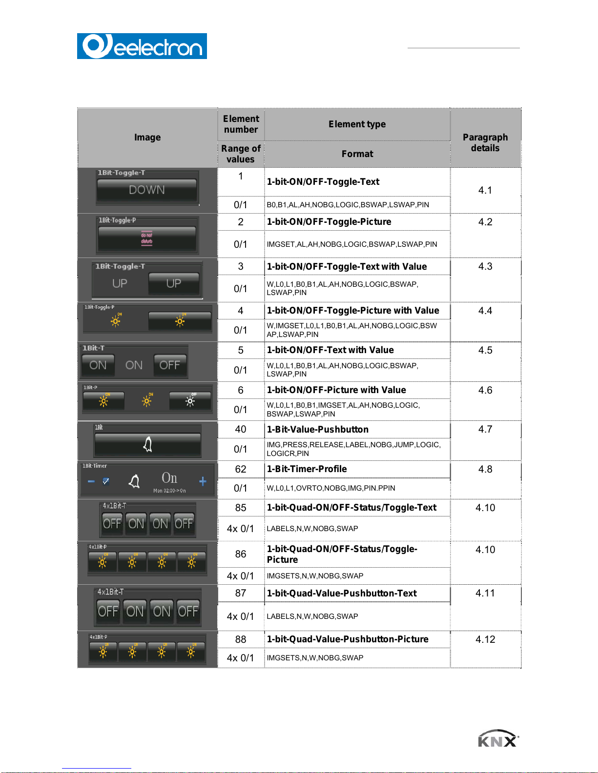
4. Overview 1bit Elements
Image
Element
number
Element type
Paragraph
details
Range of
values
Format
1
1-bit-ON/OFF-Toggle-Text
4.1
0/1
B0,B1,AL,AH,NOBG,LOGIC,BSWAP,LSWAP,PIN
2
1-bit-ON/OFF-Toggle-Picture
4.2
0/1
IMGSET,AL,AH,NOBG,LOGIC,BSWAP,LSWAP,PIN
3
1-bit-ON/OFF-Toggle-Text with Value
4.3
0/1
W,L0,L1,B0,B1,AL,AH,NOBG,LOGIC,BSWAP,
LSWAP,PIN
4
1-bit-ON/OFF-Toggle-Picture with Value
4.4
0/1
W,IMGSET,L0,L1,B0,B1,AL,AH,NOBG,LOGIC,BSW
AP,LSWAP,PIN
5
1-bit-ON/OFF-Text with Value
4.5
0/1
W,L0,L1,B0,B1,AL,AH,NOBG,LOGIC,BSWAP,
LSWAP,PIN
6
1-bit-ON/OFF-Picture with Value
4.6
0/1
W,L0,L1,B0,B1,IMGSET,AL,AH,NOBG,LOGIC,
BSWAP,LSWAP,PIN
40
1-Bit-Value-Pushbutton
4.7
0/1
IMG,PRESS,RELEASE,LABEL,NOBG,JUMP,LOGIC,
LOGICR,PIN
62
1-Bit-Timer-Profile
4.8
0/1
W,L0,L1,OVRTO,NOBG,IMG,PIN.PPIN
85
1-bit-Quad-ON/OFF-Status/Toggle-Text
4.10
4x 0/1
LABELS,N,W,NOBG,SWAP
86
1-bit-Quad-ON/OFF-Status/Toggle-
Picture
4.10
4x 0/1
IMGSETS,N,W,NOBG,SWAP
87
1-bit-Quad-Value-Pushbutton-Text
4.11
4x 0/1
LABELS,N,W,NOBG,SWAP
88
1-bit-Quad-Value-Pushbutton-Picture
4.12
4x 0/1
IMGSETS,N,W,NOBG,SWAP
VS00E01KNXFI01010007.DOC
Eelecta® Touch Panel 3,5 KNX – Product Handbook
17/156
Eelectron SpA, Via Magenta 77/22, I-20017 Rho (MI), Italia
+39 02.9316681 +39 02.93507688
info@eelectron.com www.eelectron.com
VS00E01KNXFI01010007.doc
C.F. e P.IVA 11666760159
Capitale sociale: 250.000,00€ interamente versato
Tribunale di Milano 359157-8760-07
CCIAA Milano 148549
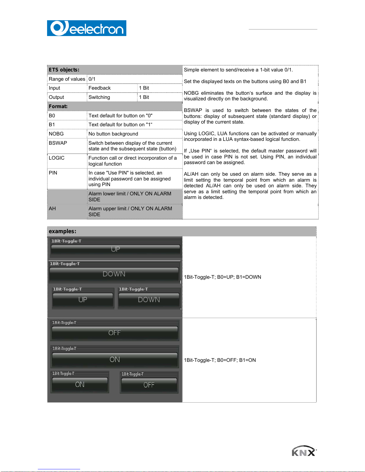
4.1 1-bit-ON/OFF-Toggle-Text
ETS objects:
Simple element to send/receive a 1-bit value 0/1.
Set the displayed texts on the buttons using B0 and B1
NOBG eliminates the button‘s surface and the display is
visualized directly on the background.
BSWAP is used to switch between the states of the
buttons: display of subsequent state (standard display) or
display of the current state.
Using LOGIC, LUA functions can be activated or manually
incorporated in a LUA syntax-based logical function.
If „Use PIN“ is selected, the default master password will
be used in case PIN is not set. Using PIN, an individual
password can be assigned.
AL/AH can only be used on alarm side. They serve as a
limit setting the temporal point from which an alarm is
detected AL/AH can only be used on alarm side. They
serve as a limit setting the temporal point from which an
alarm is detected.
Range of values 0/1
Input Feedback 1 Bit
Output Switching 1 Bit
Format:
B0 Text default for button on "0"
B1 Text default for button on "1“
NOBG No button background
BSWAP Switch between display of the current
state and the subsequent state (button)
LOGIC Function call or direct incorporation of a
logical function
PIN In case "Use PIN" is selected, an
individual password can be assigned
using PIN
AL Alarm lower limit / ONLY ON ALARM
SIDE
AH Alarm upper limit / ONLY ON ALARM
SIDE
examples:
1Bit-Toggle-T; B0=UP; B1=DOWN
1Bit-Toggle-T; B0=OFF; B1=ON
VS00E01KNXFI01010007.DOC
Eelecta® Touch Panel 3,5 KNX – Product Handbook
18/156
Eelectron SpA, Via Magenta 77/22, I-20017 Rho (MI), Italia
+39 02.9316681 +39 02.93507688
info@eelectron.com www.eelectron.com
VS00E01KNXFI01010007.doc
C.F. e P.IVA 11666760159
Capitale sociale: 250.000,00€ interamente versato
Tribunale di Milano 359157-8760-07
CCIAA Milano 148549
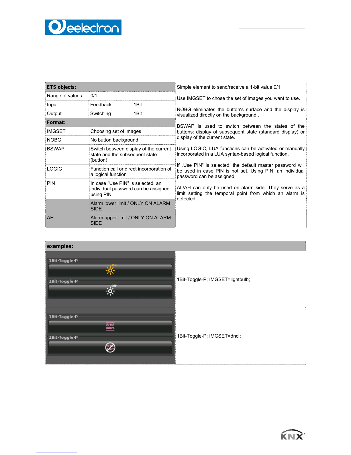
4.2 1-bit-ON/OFF-Toggle-Picture
ETS objects:
Simple element to send/receive a 1-bit value 0/1.
Use IMGSET to chose the set of images you want to use.
NOBG eliminates the button‘s surface and the display is
visualized directly on the background..
BSWAP is used to switch between the states of the
buttons: display of subsequent state (standard display) or
display of the current state.
Using LOGIC, LUA functions can be activated or manually
incorporated in a LUA syntax-based logical function.
If „Use PIN“ is selected, the default master password will
be used in case PIN is not set. Using PIN, an individual
password can be assigned.
AL/AH can only be used on alarm side. They serve as a
limit setting the temporal point from which an alarm is
detected.
Range of values 0/1
Input Feedback 1Bit
Output Switching 1Bit
Format:
IMGSET Choosing set of images
NOBG No button background
BSWAP Switch between display of the current
state and the subsequent state
(button)
LOGIC Function call or direct incorporation of
a logical function
PIN In case "Use PIN" is selected, an
individual password can be assigned
using PIN
AL Alarm lower limit / ONLY ON ALARM
SIDE
AH Alarm upper limit / ONLY ON ALARM
SIDE
examples:
1Bit-Toggle-P; IMGSET=lightbulb;
1Bit-Toggle-P; IMGSET=dnd ;
VS00E01KNXFI01010007.DOC
Eelecta® Touch Panel 3,5 KNX – Product Handbook
19/156
Eelectron SpA, Via Magenta 77/22, I-20017 Rho (MI), Italia
+39 02.9316681 +39 02.93507688
info@eelectron.com www.eelectron.com
VS00E01KNXFI01010007.doc
C.F. e P.IVA 11666760159
Capitale sociale: 250.000,00€ interamente versato
Tribunale di Milano 359157-8760-07
CCIAA Milano 148549
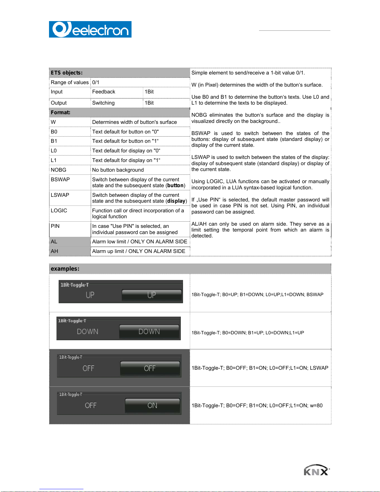
4.3 1-bit-ON/OFF-Toggle-Text with Value
ETS objects:
Simple element to send/receive a 1-bit value 0/1.
W (in Pixel) determines the width of the button‘s surface.
Use B0 and B1 to determine the button‘s texts. Use L0 and
L1 to determine the texts to be displayed.
NOBG eliminates the button‘s surface and the display is
visualized directly on the background..
BSWAP is used to switch between the states of the
buttons: display of subsequent state (standard display) or
display of the current state.
LSWAP is used to switch between the states of the display:
display of subsequent state (standard display) or display of
the current state.
Using LOGIC, LUA functions can be activated or manually
incorporated in a LUA syntax-based logical function.
If „Use PIN“ is selected, the default master password will
be used in case PIN is not set. Using PIN, an individual
password can be assigned.
AL/AH can only be used on alarm side. They serve as a
limit setting the temporal point from which an alarm is
detected.
Range of values 0/1
Input Feedback 1Bit
Output Switching 1Bit
Format:
W Determines width of button's surface
B0 Text default for button on "0"
B1 Text default for button on "1“
L0 Text default for display on "0“
L1 Text default for display on "1“
NOBG No button background
BSWAP Switch between display of the current
state and the subsequent state (button)
LSWAP Switch between display of the current
state and the subsequent state (display)
LOGIC Function call or direct incorporation of a
logical function
PIN In case "Use PIN" is selected, an
individual password can be assigned
AL Alarm low limit / ONLY ON ALARM SIDE
AH Alarm up limit / ONLY ON ALARM SIDE
examples:
1Bit-Toggle-T; B0=UP; B1=DOWN; L0=UP;L1=DOWN; BSWAP
1Bit-Toggle-T; B0=DOWN; B1=UP; L0=DOWN;L1=UP
1Bit-Toggle-T; B0=OFF; B1=ON; L0=OFF;L1=ON; LSWAP
1Bit-Toggle-T; B0=OFF; B1=ON; L0=OFF;L1=ON; w=80

VS00E01KNXFI01010007.DOC
Eelecta® Touch Panel 3,5 KNX – Product Handbook
20/156
Eelectron SpA, Via Magenta 77/22, I-20017 Rho (MI), Italia
+39 02.9316681 +39 02.93507688
info@eelectron.com www.eelectron.com
VS00E01KNXFI01010007.doc
C.F. e P.IVA 11666760159
Capitale sociale: 250.000,00€ interamente versato
Tribunale di Milano 359157-8760-07
CCIAA Milano 148549
4.4 1-bit-ON/OFF-Toggle-Picture with Value
ETS objects:
Simple element to send/receive a 1-bit value 0/1.
W (in Pixel) determines the width of the button‘s
surface.
Use IMGSET to chose the set of images you want to
use.
Use B0 and B1 to determine the button‘s texts.
Use L0 and L1 to determine the texts to be displayed.
NOBG eliminates the button‘s surface and the display
is visualized directly on the background..
BSWAP is used to switch between the states of the
buttons: display of subsequent state (standard
display) or display of the current state.
LSWAP is used to switch between the states of the
display: display of subsequent state (standard display)
or display of the current state.
Using LOGIC, LUA functions can be activated or
manually incorporated in a LUA syntax-based logical
function.
If "Use PIN" is selected, the default master password
will be used in case PIN is not set. Using PIN, an
individual password can be assigned.
AL/AH can only be used on alarm side. They serve as
a limit setting the temporal point from which an alarm
is detected.
Range of values 0/1
Input Feedback 1Bit
Output Switching 1Bit
Format:
W Determines width of button's surface
IMGSET Choosing set of images
B0 Text default for button on "0"
B1 Text default for button on "1“
L0 Text default for display on "0“
L1 Text default for display on "1“
NOBG No button background
BSWAP Switch between display of the current state
and the subsequent state (button)
LSWAP Switch between display of the current state
and the subsequent state (display)
LOGIC Function call or direct incorporation of a
logical function
PIN In case "Use PIN" is selected, an individual
password can be assigned using PIN
AL Alarm lower limit / ONLY ON ALARM SIDE
AH Alarm upper limit / ONLY ON ALARM SIDE
examples:
1Bit-Toggle-P; B0=UP; B1=DOWN;IMGSET=lightbulb
1Bit-Toggle-P; L0=UP; L1=DOWN;IMGSET=lightbulb
1Bit-Toggle-P;IMGSET=lightbulb;BSWAP
VS00E01KNXFI01010007.DOC
Eelecta® Touch Panel 3,5 KNX – Product Handbook
21/156
Eelectron SpA, Via Magenta 77/22, I-20017 Rho (MI), Italia
+39 02.9316681 +39 02.93507688
info@eelectron.com www.eelectron.com
VS00E01KNXFI01010007.doc
C.F. e P.IVA 11666760159
Capitale sociale: 250.000,00€ interamente versato
Tribunale di Milano 359157-8760-07
CCIAA Milano 148549
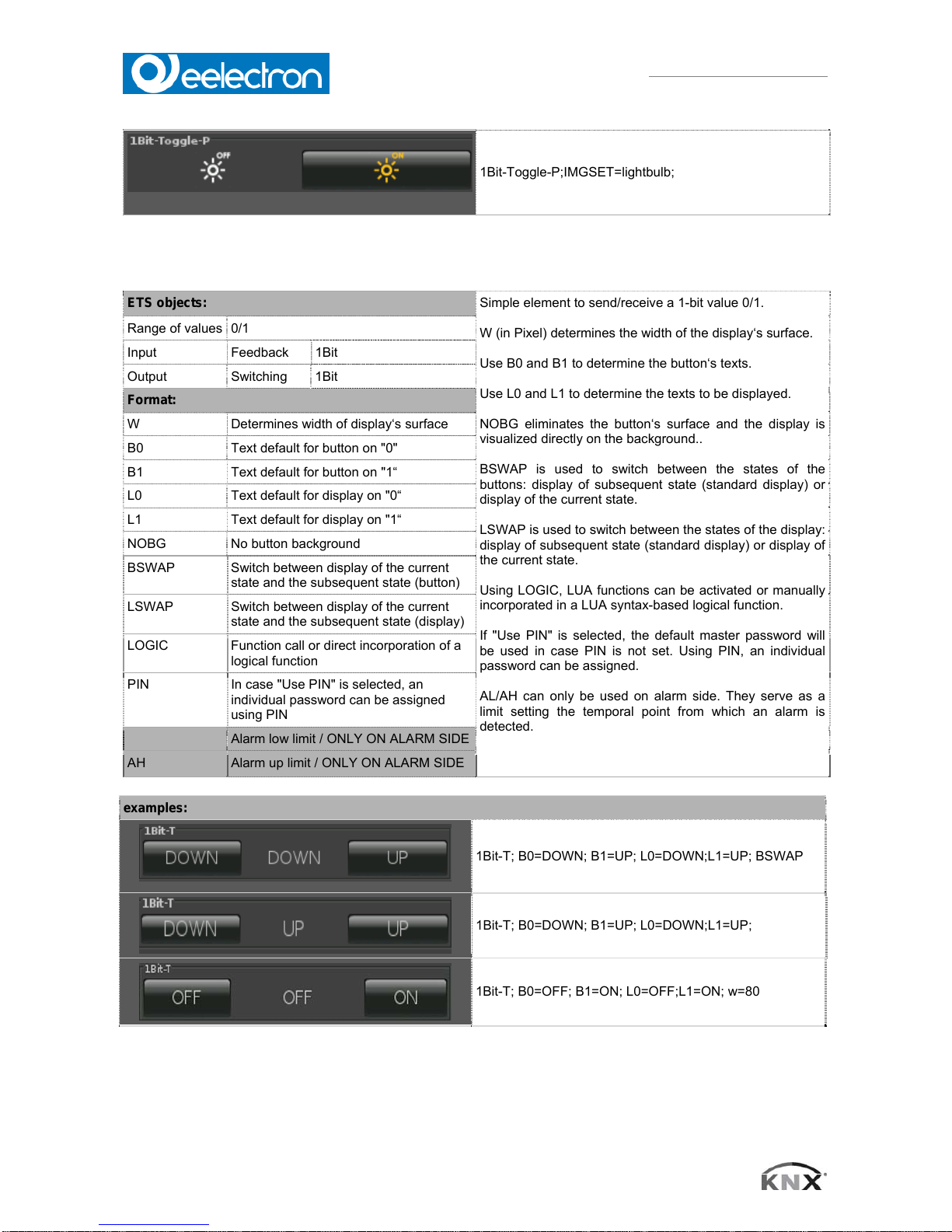
1Bit-Toggle-P;IMGSET=lightbulb;
4.5 1-bit-ON/OFF-Text with Value
ETS objects:
Simple element to send/receive a 1-bit value 0/1.
W (in Pixel) determines the width of the display‘s surface.
Use B0 and B1 to determine the button‘s texts.
Use L0 and L1 to determine the texts to be displayed.
NOBG eliminates the button‘s surface and the display is
visualized directly on the background..
BSWAP is used to switch between the states of the
buttons: display of subsequent state (standard display) or
display of the current state.
LSWAP is used to switch between the states of the display:
display of subsequent state (standard display) or display of
the current state.
Using LOGIC, LUA functions can be activated or manually
incorporated in a LUA syntax-based logical function.
If "Use PIN" is selected, the default master password will
be used in case PIN is not set. Using PIN, an individual
password can be assigned.
AL/AH can only be used on alarm side. They serve as a
limit setting the temporal point from which an alarm is
detected.
Range of values 0/1
Input Feedback 1Bit
Output Switching 1Bit
Format:
W Determines width of display‘s surface
B0 Text default for button on "0"
B1 Text default for button on "1“
L0 Text default for display on "0“
L1 Text default for display on "1“
NOBG No button background
BSWAP Switch between display of the current
state and the subsequent state (button)
LSWAP Switch between display of the current
state and the subsequent state (display)
LOGIC Function call or direct incorporation of a
logical function
PIN In case "Use PIN" is selected, an
individual password can be assigned
using PIN
AL Alarm low limit / ONLY ON ALARM SIDE
AH Alarm up limit / ONLY ON ALARM SIDE
examples:
1Bit-T; B0=DOWN; B1=UP; L0=DOWN;L1=UP; BSWAP
1Bit-T; B0=DOWN; B1=UP; L0=DOWN;L1=UP;
1Bit-T; B0=OFF; B1=ON; L0=OFF;L1=ON; w=80
VS00E01KNXFI01010007.DOC
Eelecta® Touch Panel 3,5 KNX – Product Handbook
22/156
Eelectron SpA, Via Magenta 77/22, I-20017 Rho (MI), Italia
+39 02.9316681 +39 02.93507688
info@eelectron.com www.eelectron.com
VS00E01KNXFI01010007.doc
C.F. e P.IVA 11666760159
Capitale sociale: 250.000,00€ interamente versato
Tribunale di Milano 359157-8760-07
CCIAA Milano 148549
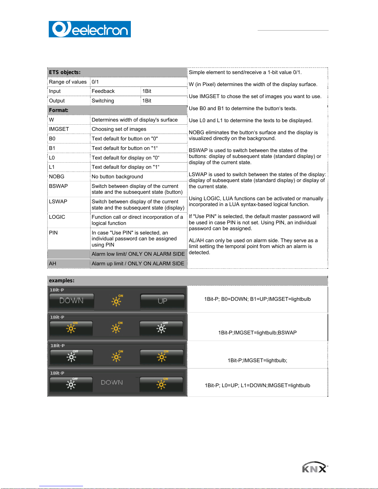
4.6 1-bit-ON/OFF-Picture with Value
ETS objects:
Simple element to send/receive a 1-bit value 0/1.
W (in Pixel) determines the width of the display surface.
Use IMGSET to chose the set of images you want to use.
Use B0 and B1 to determine the button‘s texts.
Use L0 and L1 to determine the texts to be displayed.
NOBG eliminates the button‘s surface and the display is
visualized directly on the background.
BSWAP is used to switch between the states of the
buttons: display of subsequent state (standard display) or
display of the current state.
LSWAP is used to switch between the states of the display:
display of subsequent state (standard display) or display of
the current state.
Using LOGIC, LUA functions can be activated or manually
incorporated in a LUA syntax-based logical function.
If "Use PIN" is selected, the default master password will
be used in case PIN is not set. Using PIN, an individual
password can be assigned.
AL/AH can only be used on alarm side. They serve as a
limit setting the temporal point from which an alarm is
detected.
Range of values 0/1
Input Feedback 1Bit
Output Switching 1Bit
Format:
W Determines width of display's surface
IMGSET Choosing set of images
B0 Text default for button on "0"
B1 Text default for button on "1“
L0 Text default for display on "0“
L1 Text default for display on "1“
NOBG No button background
BSWAP Switch between display of the current
state and the subsequent state (button)
LSWAP Switch between display of the current
state and the subsequent state (display)
LOGIC Function call or direct incorporation of a
logical function
PIN In case "Use PIN" is selected, an
individual password can be assigned
using PIN
AL Alarm low limit/ ONLY ON ALARM SIDE
AH Alarm up limit / ONLY ON ALARM SIDE
examples:
1Bit-P; B0=DOWN; B1=UP;IMGSET=lightbulb
1Bit-P;IMGSET=lightbulb;BSWAP
1Bit-P;IMGSET=lightbulb;
1Bit-P; L0=UP; L1=DOWN;IMGSET=lightbulb

VS00E01KNXFI01010007.DOC
Eelecta® Touch Panel 3,5 KNX – Product Handbook
23/156
Eelectron SpA, Via Magenta 77/22, I-20017 Rho (MI), Italia
+39 02.9316681 +39 02.93507688
info@eelectron.com www.eelectron.com
VS00E01KNXFI01010007.doc
C.F. e P.IVA 11666760159
Capitale sociale: 250.000,00€ interamente versato
Tribunale di Milano 359157-8760-07
CCIAA Milano 148549
4.7 1-Bit-Value-Pushbutton
ETS objects:
Simple button element to send a 1-bit value 0/1.
Using LABEL, you can define the text, or else an image
using IMG, on the button.
PRESS determines the value that will be sent when
pressing the button.
RELEASE determines the value that will be sent when
releasing the button.
NOBG eliminates the button‘s surface and the display is
visualized directly on the background.
Using LOGIC, LUA functions can be activated or manually
incorporated in a LUA syntax-based logical function which
is triggered when pressing the button.
Using LOGICR, LUA functions can be activated or
manually incorporated in a LUA syntax-based logical
function which is triggered when releasing the button.
If "Use PIN" is selected, the default master password will
be used in case PIN is not set. Using PIN, an individual
password can be assigned.
Range of values 0/1
Input - -
Output Value 1Bit
Input/Output Value B 1Bit
Format:
IMG Choosing an image
PRESS Value that will be sent when pressing
button
RELEASE Value that will be sent when releasing
button
LABEL Text default for button
NOBG No button background
JUMP Command to jump to any side
LOGIC Function call or direct incorporation of
a logical function
LOGICR Function call or direct incorporation of
a logical function
PIN In case "Use PIN" is selected, an
individual password can be assigned
using PIN
examples:
1Bit; PRESS=0;LABEL=ON
1Bit; PRESS=1;IMG=bell
1Bit; RELEASE=1;LABEL=OFF
1Bit; RELEASE=0;IMG=sound
VS00E01KNXFI01010007.DOC
Eelecta® Touch Panel 3,5 KNX – Product Handbook
24/156
Eelectron SpA, Via Magenta 77/22, I-20017 Rho (MI), Italia
+39 02.9316681 +39 02.93507688
info@eelectron.com www.eelectron.com
VS00E01KNXFI01010007.doc
C.F. e P.IVA 11666760159
Capitale sociale: 250.000,00€ interamente versato
Tribunale di Milano 359157-8760-07
CCIAA Milano 148549
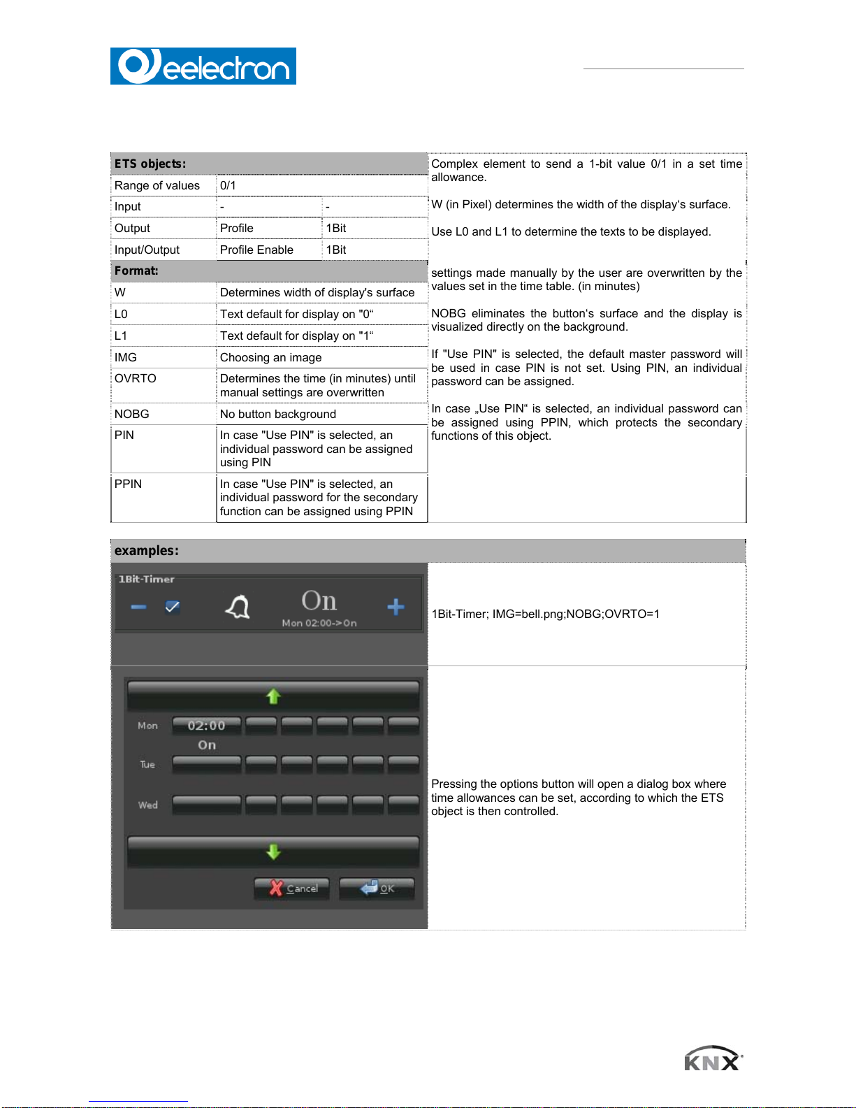
4.8 1-Bit-Timer-Profile
ETS objects:
Complex element to send a 1-bit value 0/1 in a set time
allowance.
W (in Pixel) determines the width of the display‘s surface.
Use L0 and L1 to determine the texts to be displayed.
OVRTO determines the span of time, after which the
settings made manually by the user are overwritten by the
values set in the time table. (in minutes)
NOBG eliminates the button‘s surface and the display is
visualized directly on the background.
If "Use PIN" is selected, the default master password will
be used in case PIN is not set. Using PIN, an individual
password can be assigned.
In case „Use PIN“ is selected, an individual password can
be assigned using PPIN, which protects the secondary
functions of this object.
Range of values 0/1
Input - -
Output Profile 1Bit
Input/Output Profile Enable 1Bit
Format:
W Determines width of display's surface
L0 Text default for display on "0“
L1 Text default for display on "1“
IMG Choosing an image
OVRTO Determines the time (in minutes) until
manual settings are overwritten
NOBG No button background
PIN In case "Use PIN" is selected, an
individual password can be assigned
using PIN
PPIN In case "Use PIN" is selected, an
individual password for the secondary
function can be assigned using PPIN
examples:
1Bit-Timer; IMG=bell.png;NOBG;OVRTO=1
Pressing the options button will open a dialog box where
time allowances can be set, according to which the ETS
object is then controlled.
VS00E01KNXFI01010007.DOC
Eelecta® Touch Panel 3,5 KNX – Product Handbook
25/156
Eelectron SpA, Via Magenta 77/22, I-20017 Rho (MI), Italia
+39 02.9316681 +39 02.93507688
info@eelectron.com www.eelectron.com
VS00E01KNXFI01010007.doc
C.F. e P.IVA 11666760159
Capitale sociale: 250.000,00€ interamente versato
Tribunale di Milano 359157-8760-07
CCIAA Milano 148549
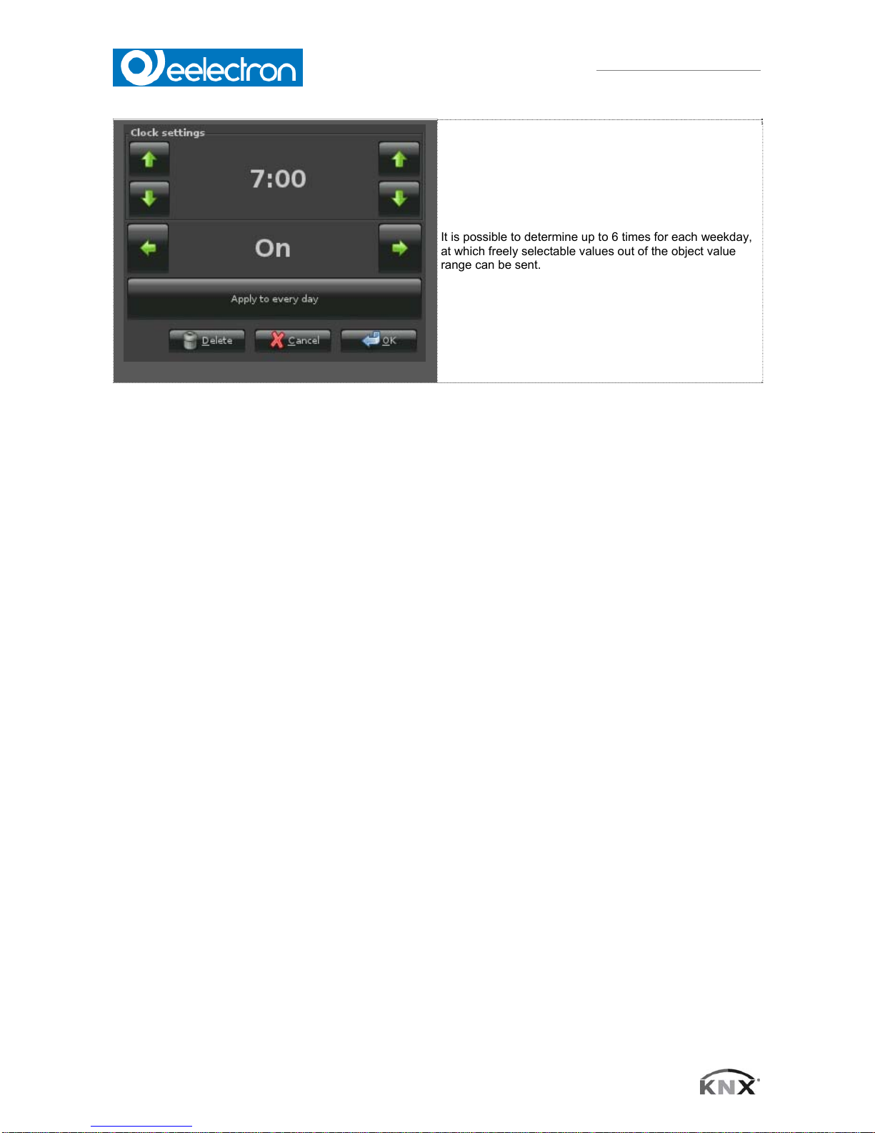
It is possible to determine up to 6 times for each weekday,
at which freely selectable values out of the object value
range can be sent.
VS00E01KNXFI01010007.DOC
Eelecta® Touch Panel 3,5 KNX – Product Handbook
26/156
Eelectron SpA, Via Magenta 77/22, I-20017 Rho (MI), Italia
+39 02.9316681 +39 02.93507688
info@eelectron.com www.eelectron.com
VS00E01KNXFI01010007.doc
C.F. e P.IVA 11666760159
Capitale sociale: 250.000,00€ interamente versato
Tribunale di Milano 359157-8760-07
CCIAA Milano 148549
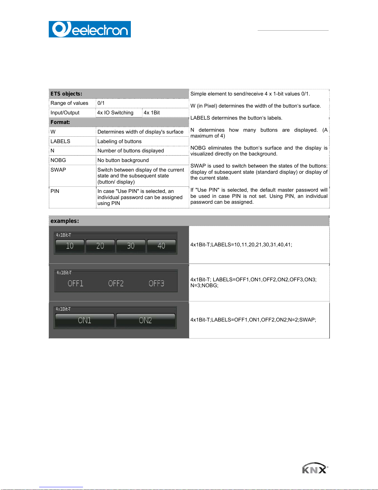
4.9 1-bit-Quad-ON/OFF-Status/Toggle-Text
ETS objects:
Simple element to send/receive 4 x 1-bit values 0/1.
W (in Pixel) determines the width of the button‘s surface.
LABELS determines the button‘s labels.
N determines how many buttons are displayed. (A
maximum of 4)
NOBG eliminates the button‘s surface and the display is
visualized directly on the background.
SWAP is used to switch between the states of the buttons:
display of subsequent state (standard display) or display of
the current state.
If "Use PIN" is selected, the default master password will
be used in case PIN is not set. Using PIN, an individual
password can be assigned.
Range of values 0/1
Input/Output 4x IO Switching 4x 1Bit
Format:
W Determines width of display's surface
LABELS Labeling of buttons
N Number of buttons displayed
NOBG No button background
SWAP Switch between display of the current
state and the subsequent state
(button/ display)
PIN In case "Use PIN" is selected, an
individual password can be assigned
using PIN
examples:
4x1Bit-T;LABELS=10,11,20,21,30,31,40,41;
4x1Bit-T; LABELS=OFF1,ON1,OFF2,ON2,OFF3,ON3;
N=3;NOBG;
4x1Bit-T;LABELS=OFF1,ON1,OFF2,ON2;N=2;SWAP;
VS00E01KNXFI01010007.DOC
Eelecta® Touch Panel 3,5 KNX – Product Handbook
27/156
Eelectron SpA, Via Magenta 77/22, I-20017 Rho (MI), Italia
+39 02.9316681 +39 02.93507688
info@eelectron.com www.eelectron.com
VS00E01KNXFI01010007.doc
C.F. e P.IVA 11666760159
Capitale sociale: 250.000,00€ interamente versato
Tribunale di Milano 359157-8760-07
CCIAA Milano 148549
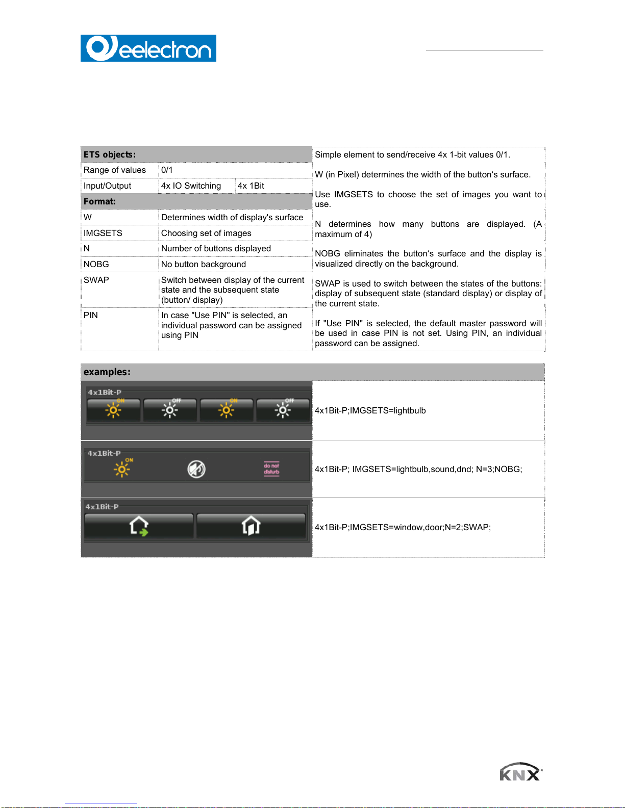
4.10 1-bit-Quad-ON/OFF-Status/Toggle-Picture
ETS objects:
Simple element to send/receive 4x 1-bit values 0/1.
W (in Pixel) determines the width of the button‘s surface.
Use IMGSETS to choose the set of images you want to
use.
N determines how many buttons are displayed. (A
maximum of 4)
NOBG eliminates the button‘s surface and the display is
visualized directly on the background.
SWAP is used to switch between the states of the buttons:
display of subsequent state (standard display) or display of
the current state.
If "Use PIN" is selected, the default master password will
be used in case PIN is not set. Using PIN, an individual
password can be assigned.
Range of values 0/1
Input/Output 4x IO Switching 4x 1Bit
Format:
W Determines width of display's surface
IMGSETS Choosing set of images
N Number of buttons displayed
NOBG No button background
SWAP Switch between display of the current
state and the subsequent state
(button/ display)
PIN In case "Use PIN" is selected, an
individual password can be assigned
using PIN
examples:
4x1Bit-P;IMGSETS=lightbulb
4x1Bit-P; IMGSETS=lightbulb,sound,dnd; N=3;NOBG;
4x1Bit-P;IMGSETS=window,door;N=2;SWAP;

VS00E01KNXFI01010007.DOC
Eelecta® Touch Panel 3,5 KNX – Product Handbook
28/156
Eelectron SpA, Via Magenta 77/22, I-20017 Rho (MI), Italia
+39 02.9316681 +39 02.93507688
info@eelectron.com www.eelectron.com
VS00E01KNXFI01010007.doc
C.F. e P.IVA 11666760159
Capitale sociale: 250.000,00€ interamente versato
Tribunale di Milano 359157-8760-07
CCIAA Milano 148549
4.11 . 1-bit-Quad-Value-Pushbutton-Text
ETS objects:
Simple element to send 4x 1-bit values "1“.
W (in Pixel) determines the width of the button‘s surface.
LABELS determines the button‘s labels
N determines how many buttons are displayed. (A
maximum of 4)
NOBG eliminates the button‘s surface and the display is
visualized directly on the background.
SWAP is used to switch between the states of the buttons:
display of subsequent state (standard display) or display of
the current state.
If "Use PIN" is selected, the default master password will
be used in case PIN is not set. Using PIN, an individual
password can be assigned
Range of values 1
Output 4x Switching 4x 1Bit
Format:
W Determines width of display's surface
LABELS Labeling of buttons
N Number of buttons displayed
NOBG No button background
SWAP Switch between display of the current
state and the subsequent state
(button/ display)
PIN In case "Use PIN" is selected, an
individual password can be assigned
using PIN
examples:
4x1Bit-T;LABELS=10,11,20,21,30,31,40,41;
4x1Bit-T; LABELS=OFF1,ON1,OFF2,ON2,OFF3,ON3;
N=3;NOBG;
4x1Bit-T;LABELS=OFF1,ON1,OFF2,ON2;N=2;SWAP;
VS00E01KNXFI01010007.DOC
Eelecta® Touch Panel 3,5 KNX – Product Handbook
29/156
Eelectron SpA, Via Magenta 77/22, I-20017 Rho (MI), Italia
+39 02.9316681 +39 02.93507688
info@eelectron.com www.eelectron.com
VS00E01KNXFI01010007.doc
C.F. e P.IVA 11666760159
Capitale sociale: 250.000,00€ interamente versato
Tribunale di Milano 359157-8760-07
CCIAA Milano 148549
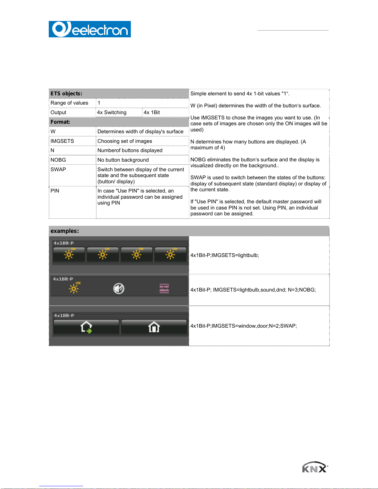
4.12 1-bit-Quad-Value-Pushbutton-Picture
ETS objects:
Simple element to send 4x 1-bit values "1“.
W (in Pixel) determines the width of the button‘s surface.
Use IMGSETS to chose the images you want to use. (In
case sets of images are chosen only the ON images will be
used)
N determines how many buttons are displayed. (A
maximum of 4)
NOBG eliminates the button‘s surface and the display is
visualized directly on the background..
SWAP is used to switch between the states of the buttons:
display of subsequent state (standard display) or display of
the current state.
If "Use PIN" is selected, the default master password will
be used in case PIN is not set. Using PIN, an individual
password can be assigned.
Range of values 1
Output 4x Switching 4x 1Bit
Format:
W Determines width of display's surface
IMGSETS Choosing set of images
N Numberof buttons displayed
NOBG No button background
SWAP Switch between display of the current
state and the subsequent state
(button/ display)
PIN In case "Use PIN" is selected, an
individual password can be assigned
using PIN
examples:
4x1Bit-P;IMGSETS=lightbulb;
4x1Bit-P; IMGSETS=lightbulb,sound,dnd; N=3;NOBG;
4x1Bit-P;IMGSETS=window,door;N=2;SWAP;
VS00E01KNXFI01010007.DOC
Eelecta® Touch Panel 3,5 KNX – Product Handbook
30/156
Eelectron SpA, Via Magenta 77/22, I-20017 Rho (MI), Italia
+39 02.9316681 +39 02.93507688
info@eelectron.com www.eelectron.com
VS00E01KNXFI01010007.doc
C.F. e P.IVA 11666760159
Capitale sociale: 250.000,00€ interamente versato
Tribunale di Milano 359157-8760-07
CCIAA Milano 148549
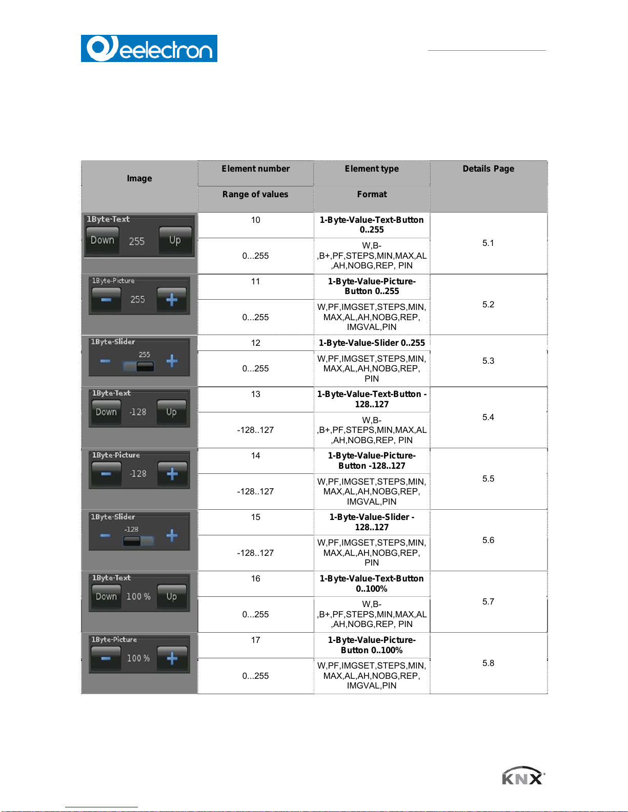
5. Overview 1Byte Elements
Image
Element number
Element type Details Page
Range of values
Format
10
1-Byte-
V
alue-Text-Button
0..255
5.1
0...255
W,B-
,B+,PF,STEPS,MIN,MAX,AL
,AH,NOBG,REP, PIN
11
1-Byte-
V
alue-Picture-
Button 0..255
5.2
0...255
W,PF,IMGSET,STEPS,MIN,
MAX,AL,AH,NOBG,REP,
IMGVAL,PIN
12
1-Byte-
V
alue-Slider 0..255
5.3
0...255
W,PF,IMGSET,STEPS,MIN,
MAX,AL,AH,NOBG,REP,
PIN
13
1-Byte-
V
alue-Text-Button -
128..127
5.4
-128..127
W,B-
,B+,PF,STEPS,MIN,MAX,AL
,AH,NOBG,REP, PIN
14
1-Byte-
V
alue-Picture-
Button -128..127
5.5
-128..127
W,PF,IMGSET,STEPS,MIN,
MAX,AL,AH,NOBG,REP,
IMGVAL,PIN
15
1-Byte-
V
alue-Slider -
128..127
5.6
-128..127
W,PF,IMGSET,STEPS,MIN,
MAX,AL,AH,NOBG,REP,
PIN
16
1-Byte-
V
alue-Text-Button
0..100%
5.7
0...255
W,B-
,B+,PF,STEPS,MIN,MAX,AL
,AH,NOBG,REP, PIN
17
1-Byte-
V
alue-Picture-
Button 0..100%
5.8
0...255
W,PF,IMGSET,STEPS,MIN,
MAX,AL,AH,NOBG,REP,
IMGVAL,PIN
 Loading...