

Eelectron TR22A01KNX, TR22A11KNX Product Handbook
Pagina 1 di 24
Transponder Reader
TR22A01KNX
TR22A11KNX
Product Handbook
Product: Transponder Reader
Order Code: TR22A01KNX - TR22A11KNX
Application Program ETS: EEL_RDT1_10 Transponder Card Reader

Pagina
2 di 24
Index
Pag.
1
General Introduction............................................................................................................ 3
2.
Technical data ......................................................................................................................... 4
2.1
Wiring Diagram....................................................................................................................... 5
2.2
Operating and display elements.................................................................................... 5
2.3
Dimension drawing............................................................................................................... 5
2.4
Mounting and wiring hints................................................................................................ 6
3.
Product and functional overview .................................................................................. 7
4.
Parameters................................................................................................................................ 9
4.1
Parameter window “General Configurations”........................................................ 9
4.2
Parameter Window “Relay 1 Configuration” ........................................................11
4.3
Parameter Window “Relay 2 Configuration” ........................................................14
4.4
Parameter Window “Input 1 Configuration” .........................................................15
5
Communication Objects..................................................................................................18
6
Application Notes................................................................................................................22

Pagina
3 di 24
1 General Introduction
Eelectron is an Italian company with a focus on designing and manufacturing electronic devices
dedicated to building and home evolution and closely related software tools.
As of year 2005, Eelectron applies to KNX association, fulfilling his requirements with the main
goal of giving a contribution to the diffusion of the world’s only open Standard for home and
building automation.
Eelectron philosophy of comprehensive aesthetic design and engagement in developing
highly innovative devices, matched with KNX Interoperability and compliance with international
requirements, has engendered Eelectron’s distinct reputation.
Eelectron experience is devoted to end users, with a constant training activity, assistance on
products and a continuous development that deserves particular attention to upcoming needs
and applications, to energy saving and to solutions directed to make Users life easier and simpler.

Pagina
4 di 24
2. Technical data
Power Supply
External Auxiliary Voltage
•
12 (24) V AC/DC ± 10%
Inputs
Number
Input Signal Voltage
Input Signal Current (close contact)
•
2 (potential free)
•
Un = 24V
•
In = 1ma
Outputs relays
Number
Output switching currents
•
2
•
24 VAC, 2A cosρ 0.6.
Control Elements
1 programming push button
Display elements
1 LED red (back) for ETS programming
1 LED red/green (front)
1 LED red (front)
1 LED amber (front)
1 LED green (front)
•
“Access Not Allowed/Allowed“
signalling
•
“Room Occupied” or “Do not
Disturb” o other alarm
•
“Room Service Call” o other alarm
•
“SOS alarm” o other alarm
Physical
specifications and
Dimensions
Housing
Colours
Dimensions
Weight
Installation
•
plastic
•
Light Grey Varnished
(TR22A01KNX),
Dark Grey (TR22A11KNX)
•
(WxHxD): 110 x 78 x 37,1 mm
•
ca. 120 g.
•
flash mounting in 2-3 modules or
wall round box Ø60mm, 40mm
deep
Electrical Safety
Pollution degree
Protection class
Safety class
Overvoltage category
•
2 (according to EN 60664-1)
•
IP20 (according to EN 60529)
•
III (according to EN 61140)
•
III (according to EN 60664-1)
CE Mark and
Certifications
CE
EIB/KNX
•
In accodance with EMC and Low
Voltage guidelines
•
According to EN 50090-1-2
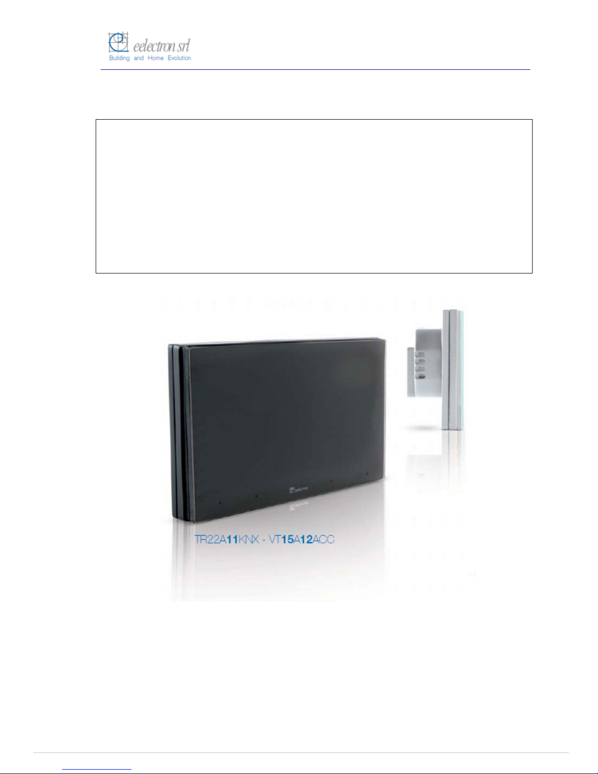
Transponder Reader
The Transponder Reader TR22A01KNX is an EIB/KNX wall
mounting device suitable to access control application.
This device can be used in any kind of building (Hotel,
Hospital, Offices, Parking, etc..) where the access control
application is required.
The device is equipped with two binary inputs (potential free
contacts) that can be used, for instance, to control whether the
door lock has been opened or closed or other signals coming
from external switches/contacts (i.e. windows, bathroom
emergency alarms, etc..).
The transponder reader is equipped also with two output relays
which can be used for any purposes, typically to open the door
or turning on the courtesy light inside the room.
The device configuration for commissioning in terms of
physical address, group addresses and parameters is done
with ETS ( Engineering Tool Software) through a download of
the Application Program.
Order Code :
TR22A01KNX (Light Grey Varnished)
TR22A11KNX (Dark Grey)
Pagina 5 di 24
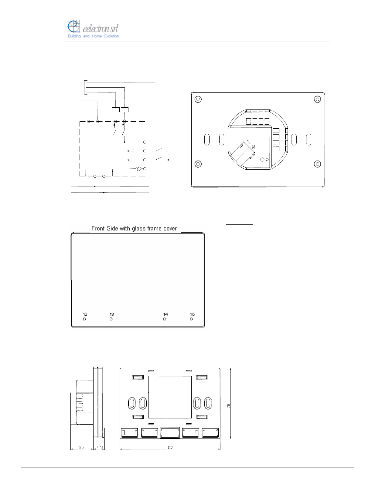
2.1 Wiring Diagram
2
.2 Operating and display elements
2.3 Dimension drawing
Connections:
1 Power Supply 12/24 Vcc/ac
2 Power Supply 12/24 Vcc/ac
3 OUT 1 terminal relay 1 (NO)
4 OUT2 terminal relay2 (NO)
5 COM Outputs
6 IN 1 (potential free)
7 IN 2 (potential free)
8 COM Inputs
11 Bus Connection Terminal:
Black = bus polarity (-)
Red = bus polarity (+)
Operating Elements:
9 Programming LED
10 Programming push button
12 Led 4
13 Led 3
14 Led 2
15 Led 1
1 2 3 4
5
6
7
8
KNX
9
10
(11)
Input 2
Out 2
Input 1
Interfaccia BUS
KNX / EIB
Com
5 6 7 8
Com
Bassa tensione
max. 60 V ac/dc 2A
Alimentazione
12/24 V ac/dc
Out 1
1 2
4 3

Pagina
6 di 24
2.4 Mounting and wiring hints
The device may be used for permanent indoor installations in dry locations within wall
boxes.
Requirements for installation
•
The device must not be connected to 230V cables.
•
The prevailing safety rules must be heeded.
•
The device must be mounted and commissioned by an authorised installer.
•
The applicable safety and accident prevention regulations must be observed.
•
The device must not be opened. Any faulty devices should be returned to manufacturer.
•
For planning and construction of electric installations, the relevant guidelines, regulations
and standards of the respective country are to be considered.
Requirements for commissioning
•
Connect each single KNX/EIB bus core inside the bus connection terminal block
observing bus polarity .
•
Slip the bus connection block into the guide slot placed on the front side of this device
and press the block down to the stop.
•
In order to commission the device, a PC with ETS2 version V1.3 or higher is required as
well as an interface to the bus, e.g. via an RS232 interface or via a USB interface.
•
The device configuration (KNX physical address assignment) is done by pressing the
programming push button located on the front of the housing.
Supplied state
•
The device is supplied with the physical address 15.15.255.
•
It is therefore necessary to load parameters and group addresses during
commissioning. However the complete application program can be reloaded if required.
•
The bus connection terminal block is included in the package.
•
The instruction sheet is included in the package.
Manutenance
•
The device is maintenance free.
•
In case of damage during transportation or storage, no repairs my be carried out by
external staff.
•
When the device is opened the right to claim under guarantee expires.

Pagina
7 di 24
3. Product and functional overview
The Transponder Reader - TR22A01KNX/TR22A11KNX is an EIB/KNX wall mounting
device suitable to access control application.
This device can be used in any kind of building (Hotel, Hospital, Offices, Parking, etc..)
where the access control application is required.
The device is equipped with two binary inputs (potential free contacts) that can be used,
for instance, to control whether the door lock has been opened or closed or other
signals coming from external switches/contacts (i.e. windows, bathroom emergency
alarms, etc..).
The transponder reader is equipped also with two output relays which can be used for
any purposes, for instance in case of Hotel application to open the door or turning on
the courtesy light inside the room.
The product provides on the front side four LEDs in order to enlighten 4 icons to display
the following states (e.g. in case of Hotel management):
Access Allowed/Not Allowed
SOS request
Service Call (clean room, etc..)
Client status (“Busy room” or “Do not Disturb”)
The LEDs and icons can be configured in association with other alarms or events (see
LEDs signalling in the “Application Notes” included).
The transponder reader can reads cards or keys at a maximum distance of 30mm from
the front side.
The access control follows a sequence where the “Build Number” has been checked at
first, then the expiration data, next the password ID for client/guest/service identification,
then the enabled days of week and hours range. In case card reading pass all checks
the door is opened, the courtesy light inside is switched on and a specific 1 bit object
associated to the identified class of user is sent. At the same time the Transponder
Reader sends the access response to the bus in order to be detected and stored by a
visualization or management software..
The reader can identifies up to four types or classes of users through the reading of four
different ranges of passwords written in the cards created with the “Transponder
Encorder” (code: TE00A01USB).
This device provides also an alarm function by sending an “Alarm” object (1bit) to alarm,
for instance, a centralized visualization software (e.g. “eAccess” or “eHotel”) that a
power failure was occurred and then recovered next. This advice can be useful to
visualization and monitoring software to update some configuration data to the readers
and to the card holders or for other purposes.
The physical address, group address and parameters are assigned and programmed
with the ETS tool software. In order to commission the device, a PC with ETS2 version
V1.3 or higher is required as well as an interface to the bus, e.g. via an RS232 interface
or via a USB interface.
This device must be configured and loaded with the following application program:
EEL_RDT1_10 Transponder Card Reader

Pagina
8 di 24
With this application program the followng functions can be parametrized and configured:
Application Program: EEL_RDT1_10 Transponder Card Reader
Max number of group addresses: 35
Max number of group address associations: 32
General
Configurations
•
Single or Multiple (max 4) user groups identification
•
Grant date and grant days control enable
•
Power failure and recovery alarm enable
Input 1 (and 2)
Configuration
•
Switching states ON or OFF can be set depending on
input pulse adge evalutation (rising or falling edge).
•
Cyclical sending option at adjustable intervals
Relay 1 Configuration
•
“General Purpose” or “Door Open” function selection
•
Normally open or closed contact setting
•
Time switching (e.g.: “Door lock timing release”)
Relay 2 Configuration
•
“General Purpose” or “Courtesy Light” function selection
•
Normally open or closed contact setting
•
Time switching (e.g.: “Courtesy light timeout”)
Note: The default settings for the options are underlined (e.g. Options: no/yes)
 Loading...