

Eelectron TM11A01KNX, TM11A11KNX Product Handbook
Pagina 1 di 30
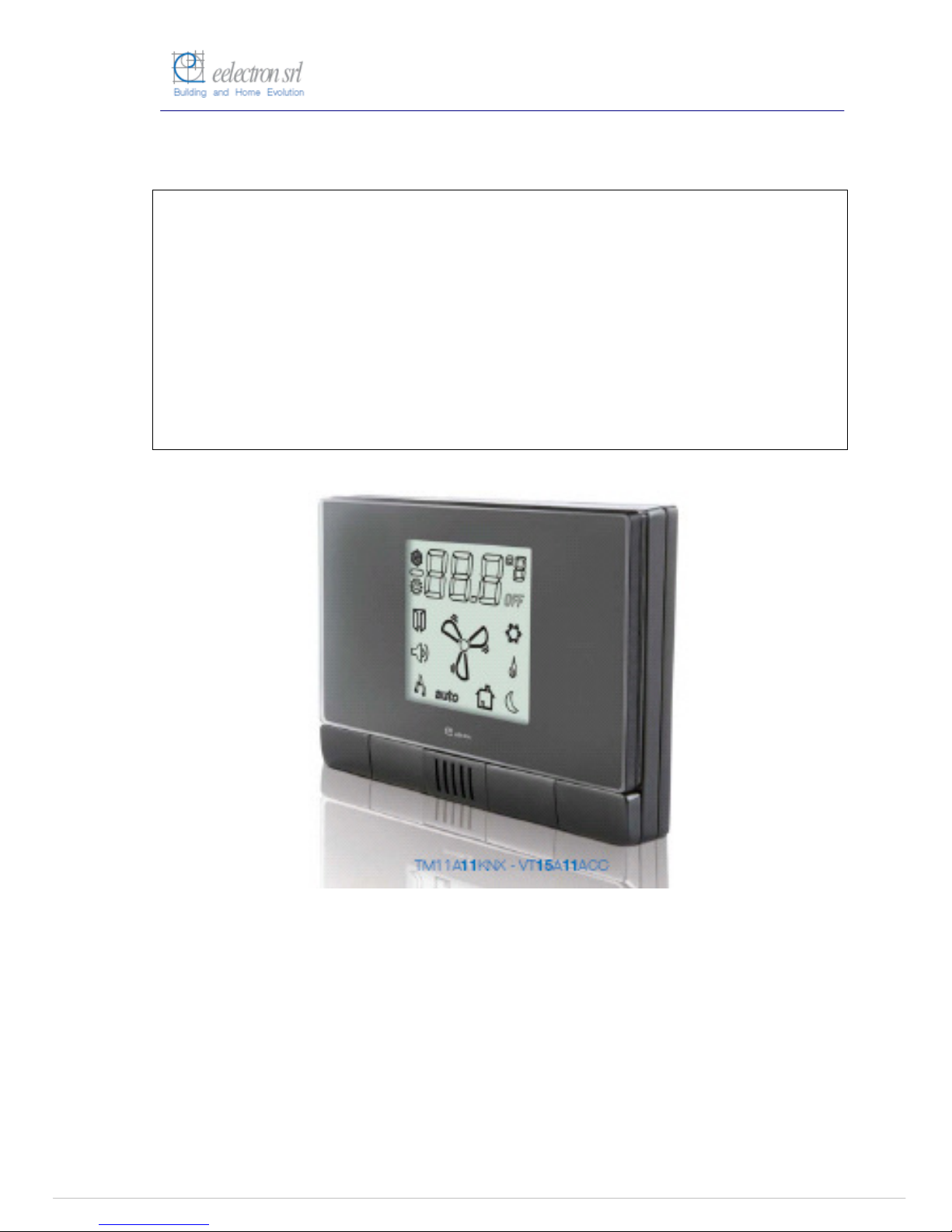
Inwall Room Thermostat
TM11A01KNX
TM11A11KNX
Product Handbook
Product: Inwall Room Thermostat
Order Code: TM11A01KNX – TM11A11KNX
Application Program ETS: EEL_RTH1_10 Room Thermostat

Pagina
2 di 30
Index
Page
1
General Introduction.................................................................................................................3
2.
Technical data ..............................................................................................................................4
2.1
Wiring Diagram............................................................................................................................5
2.2
Operating and display elements.........................................................................................5
2.3
Dimension drawing....................................................................................................................5
2.4
Mounting and wiring hints.....................................................................................................6
3.
Product and functional overview .......................................................................................7
4.
Parameters...................................................................................................................................10
4.1
Parameter window “ General Configuration”............................................................10
4.2
Parameter Window “Temperature Regulation Configuration” ........................12
4.3
Parameter Window “Setpoint Configuration”...........................................................16
4.4
Parameter Window “Input Configuration” ..................................................................19
4.5
Parameter Window “Relay Configuration”.................................................................22
5
Communication Objects.......................................................................................................25
6
Application Notes.....................................................................................................................29

Pagina
3 di 30
1 General Introduction
Eelectron is an Italian company with a focus on designing and manufacturing electronic devices
dedicated to building and home evolution and closely related software tools.
As of year 2005, Eelectron applies to KNX association, fulfilling his requirements with the main
goal of giving a contribution to the diffusion of the world’s only open Standard for home and
building automation.
Eelectron philosophy of comprehensive aesthetic design and engagement in developing
highly innovative devices, matched with KNX Interoperability and compliance with international
requirements, has engendered Eelectron’s distinct reputation.
Eelectron experience is devoted to end users, with a constant training activity, assistance on
products and a continuous development that deserves particular attention to upcoming needs
and applications, to energy saving and to solutions directed to make Users life easier and simpler.
Pagina
4 di 30
2. Technical data
Power Supply
Via bus EIB/KNX
•
21..30 V DC available from the bus
Inputs
Number
Input Signal Voltage
Input Signal Current (close contact)
•
1 (potential free)
•
Un = 24V
•
In = 1ma
Outputs relays
Number
Output switching currents
•
1
•
48 VAC, 1A (AC1)
Control Elements
1 programming push button (back side)
1 push button to increase temperature
setpoint
1 push button to decrease temperature
setpoint
1 push button to increase fan coil speed
1 push button to decrease fan coil speed
Display Elements
1 LED red (back) for ETS programming
1 LCD display B/W, size 43,5X43,5 mm
Physical
specifications and
Dimensions
Housing
Colours
Dimensions
Weight
Installation
•
plastic
•
Light Grey Varnished
(TM11A01KNX),
Dark Grey (TM11A11KNX)
•
(WxHxD): 110 x 78 x 39,8mm
•
ca.65g
•
flash mounting in 2-3 modules or
wall round box Ø60mm, 40mm
deep
Electrical Safety
Pollution degree
Protection class
Safety class
Overvoltage category
•
2 (according to EN 60664-1)
•
IP20 (according to EN 60529)
•
III (according to EN 61140)
•
III (according to EN 60664-1)
CE Mark and
Certifications
CE
EIB/KNX
•
In accodance with EMC and Low
Voltage guidelines
•
According to EN 50090-1-2
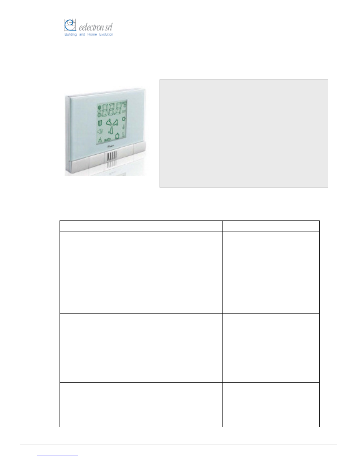
The Inwall Room Thermostat TM11A01KNX/TM11A11KNX is an
EIB/KNX wall mounting device designed for HVAC applications in
Home and Building installations (i.e. offices, hospitals, hotels,
private houses, etc..).
The device is equipped with one binary input (potential free
contact) that can be used, for instance, to control the HVAC units
whether a window has been opened (or closed) or for a general
purpose usage and one binary output relay to control fan coils or
for any different purposes.
The LCD on the front side displays information about temperature,
setpoint, fan coil speeds and operative status.
The control elements available on the front are four push buttons
for setpoint and fan coil speed modification.
La configurazione dell’apparecchio, indirizzo fisico, parametri e
oggetti di comunicazione, avviene mediante il software ETS
(Engineering Tool Software).
Order Code :
TM11A01KNX – Varnished Light Grey
TM11A11KNX – Dark Grey
Pagina
5 di 30
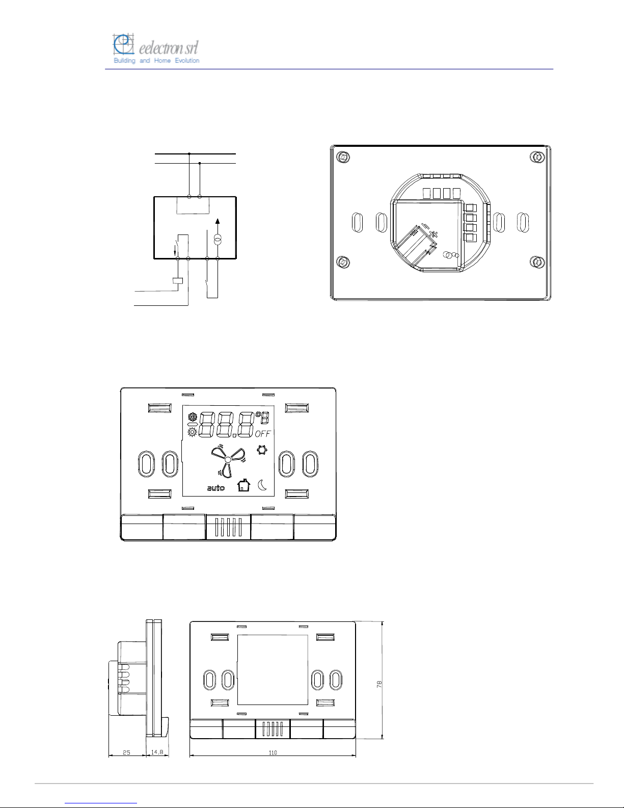
2.1 Wiring Diagram
BUS KNX
TP UART
max 60Vac/dc 1A
Out
In
5 6 7 8
2.2 Operating and display elements
2.3 Dimension drawing
5
6
7
8
9
10
KNX
(11)
12
13 15 16
14
1 2 3 4
5
6
7
8
KNX
9
10
(11)

Pagina
6 di 30
2.4 Mounting and wiring hints
The device may be used for permanent indoor installations in dry locations within wall
boxes.
Requirements for installation
•
The device must not be connected to 230V cables.
•
The prevailing safety rules must be heeded.
•
The device must be mounted and commissioned by an authorised installer.
•
The applicable safety and accident prevention regulations must be observed.
•
The device must not be opened. Any faulty devices should be returned to manufacturer.
•
For planning and construction of electric installations, the relevant guidelines, regulations
and standards of the respective country are to be considered.
Requirements for commissioning
•
Connect each single KNX/EIB bus core inside the bus connection terminal block
observing bus polarity .
•
Slip the bus connection block into the guide slot placed on the front side of this device
and press the block down to the stop.
•
In order to commission the device, a PC with ETS2 version V1.3 or higher is required as
well as an interface to the bus, e.g. via an RS232 interface or via a USB interface.
•
The device configuration (KNX physical address assignment) is done by pressing the
programming push button located on the front of the housing.
Supplied state
•
The device is supplied with the physical address 15.15.255.
•
It is therefore necessary to load parameters and group addresses during
commissioning. However the complete application program can be reloaded if required.
•
The bus connection terminal block is included in the package.
•
The instruction sheet is included in the package.
Manutenance
•
The device is maintenance free.
•
In case of damage during transportation or storage, no repairs my be carried out by
external staff.
•
When the device is opened the right to claim under guarantee expires.

Pagina
7 di 30
3. Product and functional overview
The Inwall Room Thermostat TM11A01KNX/TM11A11KNX is an EIB/KNX wall mounting
device designed for HVAC applications in Home and Building installations (i.e. offices,
hospitals, hotels, private houses, etc..).
The device is equipped with one binary input (potential free contact) that can be used, for
instance, to control the HVAC units whether a window has been opened (or closed) or for
any other general purpose usage and one binary output relay to control fan coils or for any
different purposes.
The temperature control is managed with an On/Off, Proportional, Integrative or PI
algorithm and can be configured to control the following applications:
Heating and Cooling with two tubes common to both fluids (Warm and Cold).
Four circuits for heating and cooling
1, 2 or 3 fancoil speed in ON/OFF regulation
Proportioned motorized valves regulation (continuous control).
In addition to the temperature regulation described, the thermostat allows the following
operating modes:
User inside the room (Comfort mode). The regulation follows the set point that is
fixed from the control/supervision center or modified by the client.
User outside the room (Standby mode). The regulation follows the set point fixed
from the control/supervision center for this mode.
Night Application (Economy Mode). The regulation follows the set point fixed from
the control/supervision center for this mode.
Antifreeze (frost protection).
The user, using dedicated push buttons placed in front of the thermostat, can modify the
temperature setpoint and fancoil speeds.
In case user changes the fancoil speed via a front push button the thermostat pass from
automatic to manual functioning. The automatic functioning mode is restored when the
functioning scheme changes (Comfort, Standby or Economy).
In the thermostat the following parameters can be configured:
Room Temperature Set Point (from 5,0 to 45.0°C or °F correspondent value). The
set point is normally fixed from the control/supervision centre. The client can vary
the set point trough dedicated buttons. The variation can be executed in between
limits fixed from the control/supervision centre (minimum and maximum).
Fan Coil Speed (OFF,1, 2, 3). The fan coil speed is normally managed automatically
from the thermostat. If the clients modify the speed set, the thermostat is forced in
manual mode. The fan coil will get off when the temperature is reached.
Comfort temperature set point (one for cooling and one for heating). This parameter
is set from the control/supervision centre and used when the client is in the room.
Stand by Temperature Set Point (one for cooling and one for heating). This
parameter is set from the control/supervision centre and used when the client is not
in the room.
Economy Set Point (one for cooling and one for heating). This parameter is set from
the control/supervision centre and used when the room is not assigned or by night
to generate an energy saving.
System Type: Two Tubes ON/OFF (only heating, only cooling or both), Four Tubes
ON/OFF (heating and cooling with independent lines), Two Tubes with proportional
command, Four Tubes with proportional command. The parameter is fixed while
installing or testing the system, using ETS SW.
Valves Type: ON/OFF Valves, or Motorized. The parameter is fixed while installing
or testing the system, using ETS SW.
Pagina
8 di 30
Commutation Range between Heating and Cooling. Heating or Cooling action can
be forced from the control/supervision centre and at each season change.
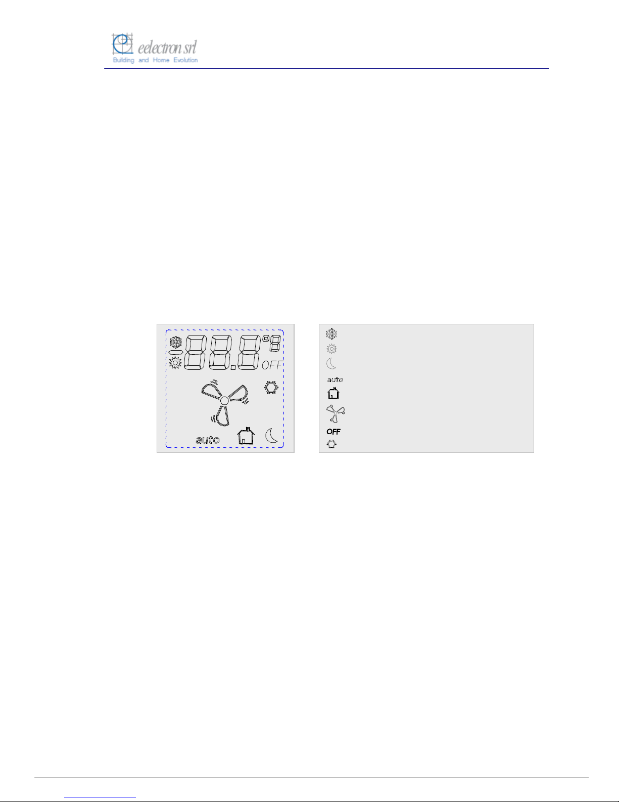
On the display the following information are visualized (see Fig. 1):
Setpoint. The value is displayed in the LCD with XX.X°C format (or in the
correspondent °F value to be selected while installing the system). Using the Set
point variation buttons, the temperature is varied in a range fixed with ETS. Pushing
continuously a button, the value will initially vary of 0,1°C and will proportionally
accelerate the variation speed.
Actual Temperature. In the LCD is displayed the real or actual temperature, in
XX.X°C Format (or in the correspondent °F value to be selected while installing the
system).
Fan Coil Speed Visualisation. The value, from speed 1 to speed 3, is indicated by a
specific icon on the display. This indication is visualised if the system is configured
for fancoil usage.
Some icons concerning actual operative status.
Fig. 1: Display and icons
The thermostat transmits to the KNX/EIB bus the following information:
Real Setpoint Value (also cyclically sent with time period setting)
Real Temperature (also cyclically sent with time period setting)
Objects for actuator command (Fan coil and Valves)
Power failure (and restore) alarm, if enabled.
This device provides also an alarm function by sending an “Alarm” object (1bit) to alarm, for
instance, a centralized visualization software that a power failure has been occurred and
then recovered next (this object is sent as the power supply is recovered).
The physical address, group address and parameters are assigned and programmed with
the ETS tool software. In order to commission the device, a PC with ETS2 version V1.3 or
higher is required as well as an interface to the bus, e.g. via an RS232 interface or via a
USB interface.
The device TM11A01KNX/TM11A11KNX must be configured and loaded with the
following application program: EEL_RTH1_10 Room Thermostat
Climatizzazione
Riscaldamento
Funzionamento Notturno (Economy)
Funzionamento Automatico
Funzione cliente in camera o stand-by
Velocità fan-coil
Spento
Antigelo

Pagina
9 di 30
With this application program the followng functions can be parametrized and configured:
Application Program: EEL_RTH1_10 Room Thermostat
Max number of group addresses: 35
Max number of group address associations: 32
General Configuration
•
Cyclical sending of actual temperature (environment)
•
Cyclical sending of actual setpont temperature
•
Power failure and recovery alarm enable
Temperature
Regulation
Configuration
•
Type of temperature regulation (ON/OFF, P, I, PI)
•
Type of HVAC plant (2/4 tubes ON/OFF, 2/4 tubes
Proportional)
•
Fan Coil type (1,2,3 speeds or proportional regulation)
•
Temperature sensor adjastment (calibration)
•
Temperature coefficient regulation (hysteresis)
Setpoint Configuration
•
Setpoint settings for Comfort, Stand-by, Economy modes
in Summer/Winter conditions (Cooling/Heating)
•
Setpoint antifreeze winter (frost protection)
•
User’s setpont temperature range regulation setting
Input Configuration
•
“Window Switch” or “General Purpose” functions setting
•
Window switch mode (normally opened or closed)
•
If “General Purpose” switching states ON or OFF can be
set depending on input pulse adge evalutation (rising or
falling edge).
•
Cyclical sending option at adjustable intervals
Configurazione
Relay di uscita
•
“General Purpose” or “Velocity V1 Fan Coil”
•
Normally open or closed contact setting
•
Timed OFF switching (e.g.: “Door lock timing release”)).
Note: The default settings for the options are underlined (e.g. Options: no/yes)
 Loading...