

Eelectron PD00D01KNX Product Handbook
PD00D01KNX– Product Handbook
Eelectron Spa
Via Claudio Monteverdi 6, I-20025 Legnano (MI), Italia
Tel +39 0331.500802 - Fax +39 0331.564826
info@eelectron.com www.eelectron.com
C.F. e P.IVA 11666760159 - Capitale sociale: 800.000,00 interamente versato
Tribunale di Milano 359157-8760-07 - CCIAA Milano 1486549
PD00D01KNXFI00030103.DOCX
1/42
PRESENCE DETECTOR, CONSTANT LIGHT CONTROLLER
PD00D01KNX
Product Handbook
Product:
PD00D01KNX
Description:
PRESENCE DETECTOR, CONSTANT CONTROLLER
Document
Version: 1.3
Date:
03/10/2017

PD00D01KNX– Product Handbook
Eelectron Spa
Via Claudio Monteverdi 6, I-20025 Legnano (MI), Italia
Tel +39 0331.500802 - Fax +39 0331.564826
info@eelectron.com www.eelectron.com
C.F. e P.IVA 11666760159 - Capitale sociale: 800.000,00 interamente versato
Tribunale di Milano 359157-8760-07 - CCIAA Milano 1486549
PD00D01KNXFI00030103.DOCX
2/42
INDEX
General Introduction .............................................................................................................. 5
Product and functional overview ............................................................................................ 5
Presence / Motion detector ................................................................................................ 5
Presence detector (HVAC) ................................................................................................ 6
Functionality of the Presence detector / Motion detector / HVAC-detector ......................... 7
Operating Sequence ..................................................................................................... 7
Use as single device or as main detector, respectively secondary detector .................. 7
Brightness measuring – adjustable via KNX ................................................................. 8
Integrated 2-level light control (switching) ..................................................................... 8
Integrated constant light level control (dimming) ........................................................... 9
Application program ........................................................................................................ 11
Commissioning / Factory default settings ........................................................................ 11
Parameter and Communication objects ............................................................................... 12
General ........................................................................................................................... 12
Parameter General ..................................................................................................... 12
Parameter Functional blocks ....................................................................................... 13
Brightness measuring ...................................................................................................... 14
Parameter ................................ ................................................................ ................... 14
Communication objects ............................................................................................... 15
Motion detector / Presence detector ................................................................................ 16
Parameter ................................ ................................................................ ................... 16
Begin of Motion ........................................................................................................... 18
Overshoot time ........................................................................................................... 19
End of Motion.............................................................................................................. 20
Communication objects motion detector ..................................................................... 21
Communication objects presence detector ................................................................. 22
HVAC-Presence detector ................................................................................................ 24
Parameter ................................ ................................................................ ................... 24
Begin of HVAC Presence ............................................................................................ 24
Overshoot time ........................................................................................................... 26
End of HVAC Presence .............................................................................................. 26
Communication objects ............................................................................................... 28
2-level light controller (on-off) .......................................................................................... 29
Parameter ................................ ................................................................ ................... 29
Switch-On ................................................................................................................... 29
Switch-Off ................................................................................................................... 30
Communication objects ............................................................................................... 30
Constant light level control continuous ............................................................................ 31
Parameter ................................ ................................................................ ................... 31
Actual value ................................................................................................................ 31
Setpoint ...................................................................................................................... 31
Controller .................................................................................................................... 32
Controller Output ........................................................................................................ 32
Slaves ......................................................................................................................... 33
Slave offset data ......................................................................................................... 33
Slave calibration data .................................................................................................. 34
Control characteristic .................................................................................................. 34
Communication objects ............................................................................................... 34
IR–Decoder ..................................................................................................................... 36
Parameter ................................ ................................................................ ................... 36

PD00D01KNX– Product Handbook
Eelectron Spa
Via Claudio Monteverdi 6, I-20025 Legnano (MI), Italia
Tel +39 0331.500802 - Fax +39 0331.564826
info@eelectron.com www.eelectron.com
C.F. e P.IVA 11666760159 - Capitale sociale: 800.000,00 interamente versato
Tribunale di Milano 359157-8760-07 - CCIAA Milano 1486549
PD00D01KNXFI00030103.DOCX
3/42
Button mode A ............................................................................................................ 37
Button Pair B [C, D, E, F] ............................................................................................ 39
Communication objects ............................................................................................... 39
Appendix .............................................................................................................................. 40
Determination of the correction factor of the brightness sensor (calibration) .................... 40
Determination of the control characteristic ....................................................................... 41
Determination of characteristic of used lights in the room ................................................ 41
Example of configuration ................................................................................................. 42

PD00D01KNX– Product Handbook
Eelectron Spa
Via Claudio Monteverdi 6, I-20025 Legnano (MI), Italia
Tel +39 0331.500802 - Fax +39 0331.564826
info@eelectron.com www.eelectron.com
C.F. e P.IVA 11666760159 - Capitale sociale: 800.000,00 interamente versato
Tribunale di Milano 359157-8760-07 - CCIAA Milano 1486549
PD00D01KNXFI00030103.DOCX
4/42
Any information inside this manual can be changed without advice.
This handbook can be download freely from the website: www.eelectron.com
Exclusion of liability:
Despite checking that the contents of this document match the hardware and software, deviations
cannot be completely excluded. We therefore cannot accept any liability for this.
Any necessary corrections will be incorporated into newer versions of this manual.
Symbol for relevant information
Symbol for warning

PD00D01KNX– Product Handbook
Eelectron Spa
Via Claudio Monteverdi 6, I-20025 Legnano (MI), Italia
Tel +39 0331.500802 - Fax +39 0331.564826
info@eelectron.com www.eelectron.com
C.F. e P.IVA 11666760159 - Capitale sociale: 800.000,00 interamente versato
Tribunale di Milano 359157-8760-07 - CCIAA Milano 1486549
PD00D01KNXFI00030103.DOCX
5/42
General Introduction
This manual is intended to be used by installers and describes functions and parameters of the
device PD00D01KNX and how is possible to change settings and configurations using ETS
software tool.
Product and functional overview
The device is a presence/motion detector with integrated constant light level control. The device
communicates via KNX with actuators or other KNX devices. It is designed for mounting on the
ceiling. Owing to its tilting sensor head, the device can be aligned with the required capture area.
The main application for the device is automatic control of the lighting on an office workplace.
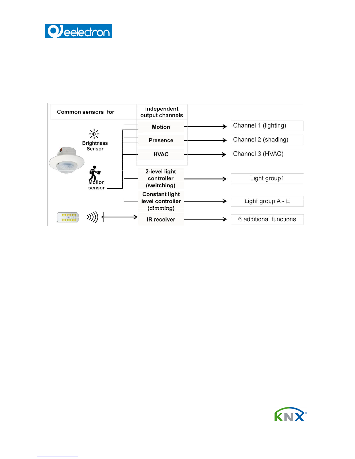
Presence / Motion detector
The detector senses the presence of a person or that there is no longer anyone in its detection
area. The detector signal can be analyzed via two separate communication channels, termed
motion detector and presence detector. The detection range is identical for all channels. Each
channel can be locked individually via communication objects.
PD00D01KNX– Product Handbook
Eelectron Spa
Via Claudio Monteverdi 6, I-20025 Legnano (MI), Italia
Tel +39 0331.500802 - Fax +39 0331.564826
info@eelectron.com www.eelectron.com
C.F. e P.IVA 11666760159 - Capitale sociale: 800.000,00 interamente versato
Tribunale di Milano 359157-8760-07 - CCIAA Milano 1486549
PD00D01KNXFI00030103.DOCX
6/42
Presence detector (HVAC)
The detector has an additional control output for HVAC applications.
For example, this function can switch systems that are used for heating, ventilating and climate
control (HVAC) of the room from “Energy saving mode” in an unused room to “Comfort mode” in an
occupied room and back to “Energy saving mode”, when the room is again unoccupied.
Fig. 1 Three independent configuration detector channels for different applications
PD00D01KNX– Product Handbook
Eelectron Spa
Via Claudio Monteverdi 6, I-20025 Legnano (MI), Italia
Tel +39 0331.500802 - Fax +39 0331.564826
info@eelectron.com www.eelectron.com
C.F. e P.IVA 11666760159 - Capitale sociale: 800.000,00 interamente versato
Tribunale di Milano 359157-8760-07 - CCIAA Milano 1486549
PD00D01KNXFI00030103.DOCX
7/42
Functionality of the Presence detector / Motion detector /
HVAC-detector
For each detector channel, 4 communication objects are available, overall 12 different
communication objects. It is possible to send one or two KNX telegrams at the beginning and at
the end of a detected presence, according to configuration. The values of the communication
objects are configured for each functional block (motion detector, presence detector, HVACdetector) via corresponding parameters.
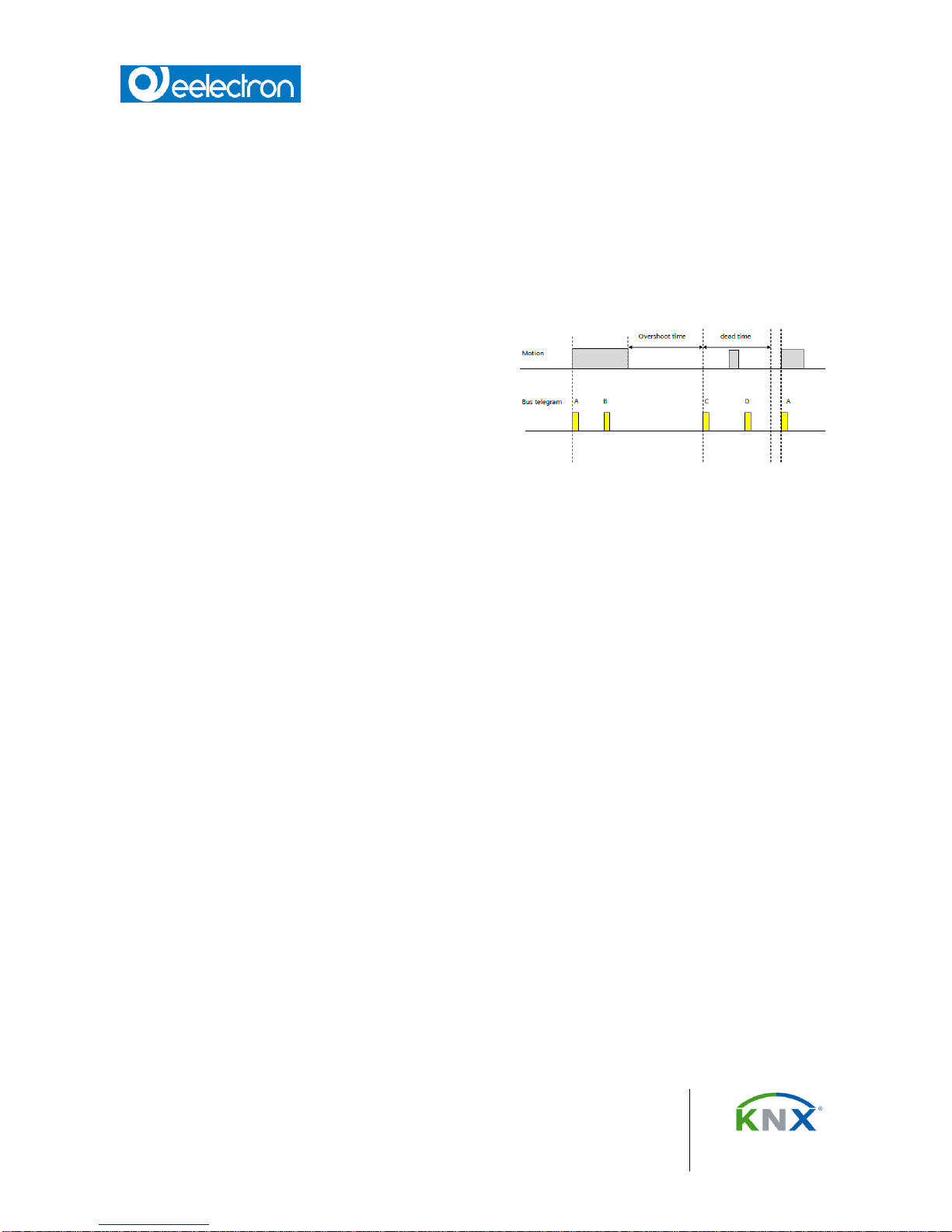
Each time a presence is detected, the overshoot
time is started. Its duration is configurable for each
functional block separately. The end of presence is
determined by the end of the overshoot time.
The duration of the dead time is also configurable
per functional block. It is used to protect the
actuators that are connected to the detector. If a
presence is detected during the dead time, neither
telegrams are sent nor the overshoot time is started.
In the following the telegrams, which are send at the beginning of a presence, are called A and B,
the telegrams, which are sent at the end of a presence, are called C and D.
Operating Sequence
After the device has detected a presence, telegram A is sent immediately. If it has been configured
to send also a tele-gram B, then telegram B is sent after the configured time (optionally also
cyclically).
If there are no motions any more, at the end of the overshoot time telegram C and (if configured)
telegram D are sent. Telegram D can also be sent cyclically.
If there are motions during the overshoot time is running, the overshoot time is restarted.
Use as single device or as main detector, respectively secondary detector
The detector can be operated as an independent device, as the main or secondary detector.
According to the requirement, additional presence detectors can be connected with the “main
detector” via KNX as “secondary detectors” to extend the presence detection zone. “Secondary
detectors” supply motion information only to the main detector.
Fig. 2 Flowchart
PD00D01KNX– Product Handbook
Eelectron Spa
Via Claudio Monteverdi 6, I-20025 Legnano (MI), Italia
Tel +39 0331.500802 - Fax +39 0331.564826
info@eelectron.com www.eelectron.com
C.F. e P.IVA 11666760159 - Capitale sociale: 800.000,00 interamente versato
Tribunale di Milano 359157-8760-07 - CCIAA Milano 1486549
PD00D01KNXFI00030103.DOCX
8/42
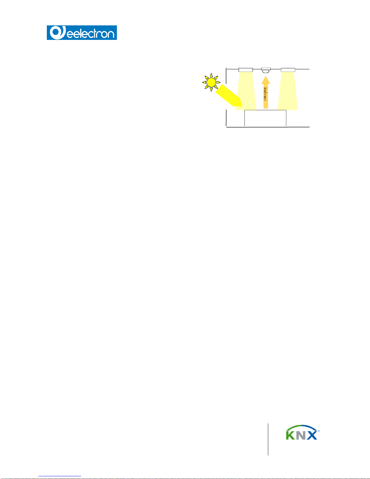
Brightness measuring – adjustable via KNX
The device contains an independent light sensor.
The signal measured there is available both at the
KNX and internally.
Because the light sensor measures directly, it must
be possible to calibrate it for indirect measurement,
so that it can be adapted to the different installation
sites. Rapid brightness fluctuations are filtered out.
The measurement range of the internal light sensor
is between 20 and 1000 Lux.
The settings determine whether the brightness value computed by the device or a brightness value
received from outside is used for the detector's remaining functional blocks.
For indirect brightness measuring a maximal distance of 2,8 m is recommended. In case of larger
distances the measuring can be realized via a reference area with 2,8 m distance.
Integrated 2-level light control (switching)
If the brightness controller is enabled (automatic mode) the lighting is switched on as soon as the
brightness falls below a set lower threshold. The lighting is switched off if the set upper brightness
threshold is exceeded. The brightness thresh-olds are variable either via parameters or via
communication objects.
The controller can also be operated semi-automatically by separating into two individual switching
objects for exceeding or falling below the threshold. In this way, it can be switched to “Only on” or
“Only off.”
If the controller receives a switching or dimming command via the associated communication
object over KNX, then this is deemed an external override and the controller switches automatic
mode off. This change of status is sent simultaneously on the bus via the “Automatic Status”
object.
Fig. 3 Indirect brightness measuring
PD00D01KNX– Product Handbook
Eelectron Spa
Via Claudio Monteverdi 6, I-20025 Legnano (MI), Italia
Tel +39 0331.500802 - Fax +39 0331.564826
info@eelectron.com www.eelectron.com
C.F. e P.IVA 11666760159 - Capitale sociale: 800.000,00 interamente versato
Tribunale di Milano 359157-8760-07 - CCIAA Milano 1486549
PD00D01KNXFI00030103.DOCX
9/42
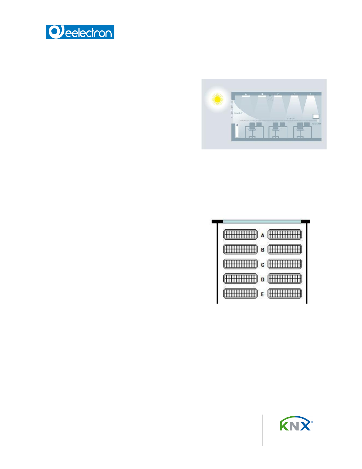
Integrated constant light level control (dimming)
The luminance of the day light falling through a window into a room decreases in the room with the
distance from the window.
Depending on lamp type, the lighting is controlled to
the preset brightness value via dimming actuators or
switching/dimming actuators. The brightness setpoint
may be configured via a parameter or set via a
communication object.
For optimum use of the day light penetrating the room
the presence detector with constant light level control
offers the option to control a main lighting group
directly and up to four additional lighting control groups
each via their own characteristic curve and their own
controller (master/slave operation).
All lighting groups are dimmed to the same set point value. This allows controlling the light level in
a room with only one presence detector with constant light level control. Depending on the relative
distance of the additional lighting groups to the window compared to the main lighting group, each
of these additional lighting groups has to be dimmed brighter or darker than the main lighting
group.
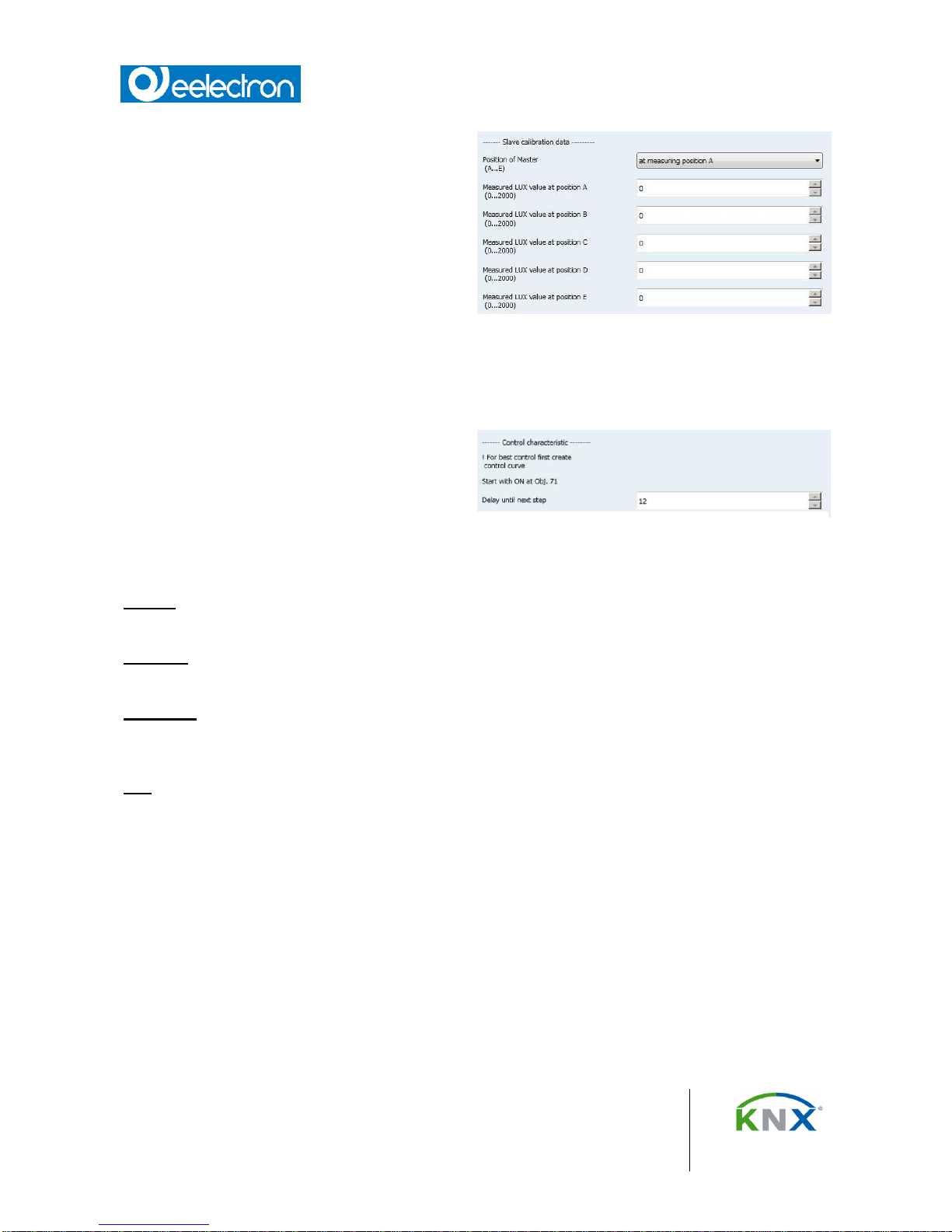
Firstly, this requires determining the installation position
of the presence detector. The presence detector can be
installed on the ceiling at any of the positions A –E. The
position of the presence detector determining the main
lighting group is in principle freely selectable. Yet, it
should be close to the window allowing the best
measurement of the daylight contribution.
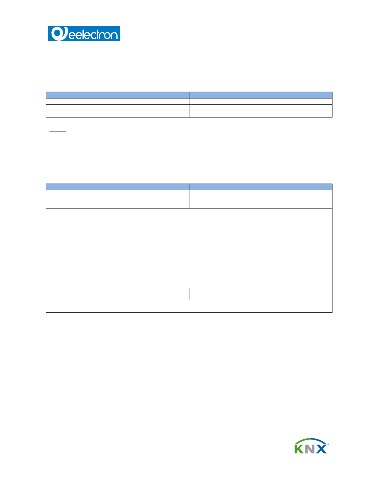
For master/slave operation the day light curve under
lighting groups A – E has to be captured. For this
purpose the artificial lighting has to be completely turned
off, such that just the natural day light is illuminating the
room. Ideally, the day light is evenly falling into the room
(no sharp shade / sunlight edges), bright, and diffused,
e.g. at noon on a bright day with overcast sky. Under each lighting group the luminance (Lux) has
to be measured manually and these values have to be entered into ETS.
Fig. 5 Position of lighting groups A-E
Fig. 4 Principal of constant light level control with
five luminaries
PD00D01KNX– Product Handbook
Eelectron Spa
Via Claudio Monteverdi 6, I-20025 Legnano (MI), Italia
Tel +39 0331.500802 - Fax +39 0331.564826
info@eelectron.com www.eelectron.com
C.F. e P.IVA 11666760159 - Capitale sociale: 800.000,00 interamente versato
Tribunale di Milano 359157-8760-07 - CCIAA Milano 1486549
PD00D01KNXFI00030103.DOCX
10/42
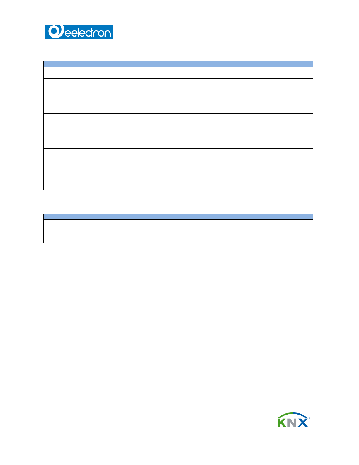
The control characteristic curve for the
additional lighting groups has to be determined
without day light. For that purpose the room
has to be completely darkened or the
characteristic curve has to be determined at
night. Sending a start signal to communication
object 71 starts the determination of the
characteristic curves. The presence detector
automatically generates 15 discrete control
values in the range 0%...100% for each
constant light level controller of the main and
additional lighting groups. The controllers send
dimming values to the corresponding lighting groups and the presence detector measures the
resulting luminance level. The period for the measurement can be configured between 10 and 60
seconds to allow for optimal pre-heating of the lamps.
After successful completion or interruption of
the calibration run the controller is in the state
„inactive“.
In case of successful completion the lighting
groups are set to 50%, in case of a failure to
minimum value ~ 6%.
During operation the constant light level controller can take up to four different states:
Active: In this state the constant lighting control is active. In a configurable period the controller
compares set point and actual values and sends a control value.
Inactive: In the state the controller is passive. The controller does not compare set point value and
actual value and does not send control values.
Stand-by: In this state the controller is passive. Different from the state “inactive” it still compares
the set point value with the actual value. On a corresponding difference between set point value
and actual value the controller automatically switches to the active state.
Off: The controller function is stopped and actuators for main and additional lighting groups are
first dimmed to a minimum and then completely turned off a second later.
Behavior on bus voltage failure / recovery
On bus voltage failure the current setpoint value is saved.
On bus voltage recovery the setpoint value is restored. The controller is in the state OFF.
Fig. 6 Parameters for measured brightness values
Fig. 7 Parameters for control characteristics

PD00D01KNX– Product Handbook
Eelectron Spa
Via Claudio Monteverdi 6, I-20025 Legnano (MI), Italia
Tel +39 0331.500802 - Fax +39 0331.564826
info@eelectron.com www.eelectron.com
C.F. e P.IVA 11666760159 - Capitale sociale: 800.000,00 interamente versato
Tribunale di Milano 359157-8760-07 - CCIAA Milano 1486549
PD00D01KNXFI00030103.DOCX
11/42
Application program
You need the KNX Engineering Tool Software (ETS) version 3.0 f and higher to load the
application program.
Commissioning / Factory default settings
After programming the device starts up with a warm-up phase of about 40 seconds.
Factory default settings
In the factory default state, the parameter Operating Mode is set to Setting Mode.
While the device is in "Setting Mode", the integrated programming LED displays the PIR sensor
state. (illuminates briefly with motion)
Programming mode
A short press of the learning button (< 2 s) enables the programming mode. This is indicated by
the programming key (LED). An additional press disables the programming mode.
Factory settings
A very long press of the learning button (> 20 s) sets the device to factory default. This will be
indicated by a continuous flashing of the programming LED for ~ 8 s.
Note
A long press of the learning button (> 5 s to 20 s) enables the connection test for commissioning
with Desigo. This mode will be disabled by an additional short press of the learning button.
Behaviour after programming
The behavior of the device after programming with the ETS is dependent on the configuration.
PD00D01KNX– Product Handbook
Eelectron Spa
Via Claudio Monteverdi 6, I-20025 Legnano (MI), Italia
Tel +39 0331.500802 - Fax +39 0331.564826
info@eelectron.com www.eelectron.com
C.F. e P.IVA 11666760159 - Capitale sociale: 800.000,00 interamente versato
Tribunale di Milano 359157-8760-07 - CCIAA Milano 1486549
PD00D01KNXFI00030103.DOCX
12/42
Parameter and Communication objects
The communication objects listed in the following paragraphs are available. Which of them are
visible and can be linked with group addresses will be determined by setting the parameters.
Description
Presence detector, constant light
Application
25 CO Presence detector, constant light
Maximum number of group addresses
160
Maximum number of assignments
200
Note: The number and type of visible objects can vary dependent on the parameter settings.
General
Parameter General
Parameter
Settings
Operating mode
normal (40s start up time)
test mode (5s ramp up without LED)
test mode (5s ramp up with LED)
Use these parameters to determine the mode.
During the test phase the test mode with or without LED can be selected. If “test mode (5s ramp up without LED)” is
selected, the LED of the detector does not flash. So it is possible to test the brightness threshold and the delay time.
In “test mode (5s ramp up with LED)”, the integrated programming LED shows the status of the motion detector. So it is
possible to test the detection range of the PIR sensor independent of the brightness value:
LED stays on:
Programming mode
LED flashes (clocking
sequence):
Device running up
LED comes on for a short time:
Motion has been detected
After the test phase has been finished, the operating mode “normal” should be selected. Afterwards the software has to
be downloaded again to the device.
Evaluate status object [sec.]
(0 = no evaluation)
0-255
4
When switching lights on and off in a detector's detection area, the change of temperature of the lighting may lead to
motion being detected incorrectly. To prevent this, the sensor is disabled for a certain time (0 - 255 seconds).
PD00D01KNX– Product Handbook
Eelectron Spa
Via Claudio Monteverdi 6, I-20025 Legnano (MI), Italia
Tel +39 0331.500802 - Fax +39 0331.564826
info@eelectron.com www.eelectron.com
C.F. e P.IVA 11666760159 - Capitale sociale: 800.000,00 interamente versato
Tribunale di Milano 359157-8760-07 - CCIAA Milano 1486549
PD00D01KNXFI00030103.DOCX
13/42
Parameter Functional blocks
Parameter
Settings
Motion detector
deactivated
active
This parameter determines whether an analysis has to be carried out according to the motion detector criteria. If it is
set to “inactive” all relevant additional parameters and objects are invisible.
Presence detector
deactivated
active
This parameter determines whether an analysis has to be carried out according to the presence detector criteria. If
it is set to “inactive” all relevant additional parameters and objects are invisible.
Presence detector (HVAC) (Heating, Ventilating, Air
Conditioning)
deactivated
active
This parameter determines whether an analysis has to be carried out according to the criteria for HVAC control. If
it is set to “inactive” all relevant additional parameters and objects are invisible.
Light control (on-off)
active
deactived
This parameter determines whether an analysis has to be carried out according to the criteria for light control. If it is
set to “inactive” all relevant additional parameters and objects are invisible.
Constant light level control continuous
deactivated
active
This parameter determines whether an analysis has to be carried out according to the criteria for constant light level
control. If it is set to “inactive” all relevant additional parameters and objects are invisible.
General Object
Obj.-no.
Object name
Function
Type
Flags 0 Status of switching actuator
On/Off
1bit
CRWT
This object notifies the detector whether the actuator controlled by the device has switched. If a change of status (1->0
or 0->1) has occurred, then the sensor is not analyzed for a configurable time. This prevents the detector sensing the
fall in temperature of an incandescent lamp that has just been switched off as motion.
 Loading...