

Eelectron IC00P01DAL Operating Instructions Manual
DALI gateway
Operating instructions
1 Safety instructions
Electrical equipment may only be installed and fitted by electrically skilled persons.
Serious injuries, fire or property damage possible. Please read and follow manual fully.
Danger of electric shock. Always disconnect before carrying out work on the devise or
load. At the same time, take into account all circuit breakers that supply dangerous
voltage to the device or load.
Danger of electric shock. Device is not suitable for disconnection from supply voltage.
The DALI control voltage is a functional extra-low voltage (FELV). On installing, ensure
safe isolation between KNX and DALI.
These instructions are an integral part of the product, and must remain with the end
customer.
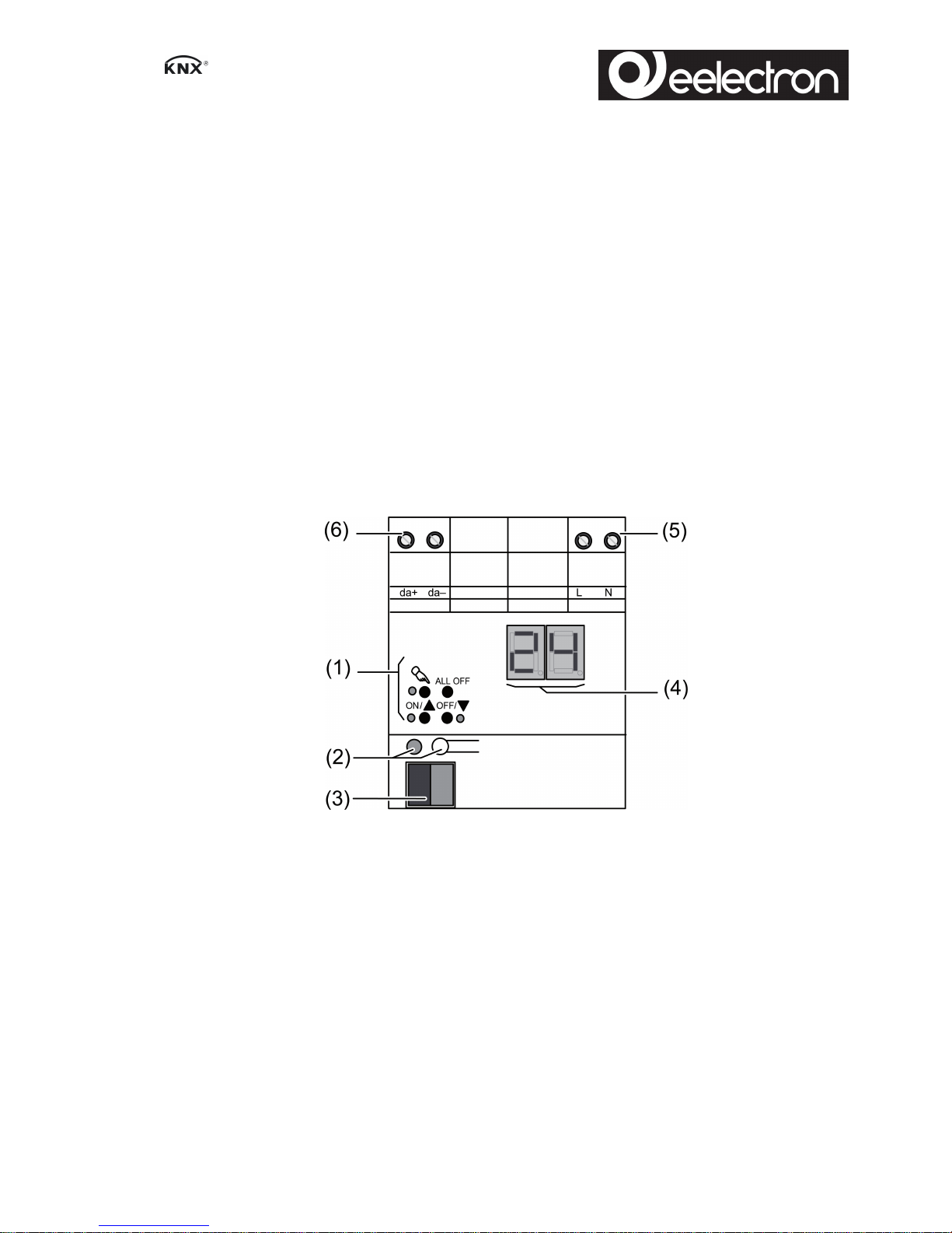
2 Device components
Figure 1
(1) Button field for manual operation
(2) Programming button and LEDs
(3) KNX connection
(4) Display of DALI devices or DALI group
(5) Connection for mains supply
(6) DALI output
3 Function
System information
This device is a product of the KNX system and complies with the KNX directives. Detailed
technical knowledge obtained in KNX training courses is a prerequisite to proper understanding.
The function of this device depends upon the software. Detailed information on loadable
software and attainable functionality as well as the software itself can be obtained from the
manufacturer´s product database.
IC00P01DAL - DALI gateway
1/9

Planning, installation and commissioning of the device are carried out with the aid of KNXcertified software. Full functionality with KNX commissioning software version ETS3.0f onwards.
An updated version of the product database, technical descriptions and conversion programs
and other auxiliary programs are available on our Internet website.
Intended use
- Controlling of luminaires and other applications with DALI operating device in KNX
installations e.g. electronic ballast
- Installation on DIN rail according to EN 60715 in distribution boxes
Product characteristics
- Control of up to 64 DALI devices in up to 32 groups
- Individual, group or central addressing
- Suitable for operation in emergency lighting systems
- 16 light scenes
- Effect control for dynamic lighting effects or colour games
- Read out DALI device state via KNX, e.g. brightness or luminaire error
- Manual operation of the DALI groups
- Restraint
- Feedback of switching state and brightness value in bus and manual mode
- Collective feedback
- Central switching function
- Disabling function for each DALI group
- Separate ON and OFF delay
- Staircase lighting timer with run-on time
- Corridor function: when combined with motion detectors, reduced continuous lighting, if no
motion is detected
- Online or offline project planning of the DALI devices with ETS plug-in
- Short circuit protection
- Surge protection
- Overload protection
- Operating hours counter
- Signal of the global switching status of the DALI devices, e.g. to switch off the mains
voltage of the DALI devices to avoid standby losses
- An individual DALI device can be exchanged during operation without software.
i Delivery state: construction site mode, the DALI groups can be operated using button field.
All DALI devices are controlled jointly.
2/9
IC00P01DAL - DALI gateway
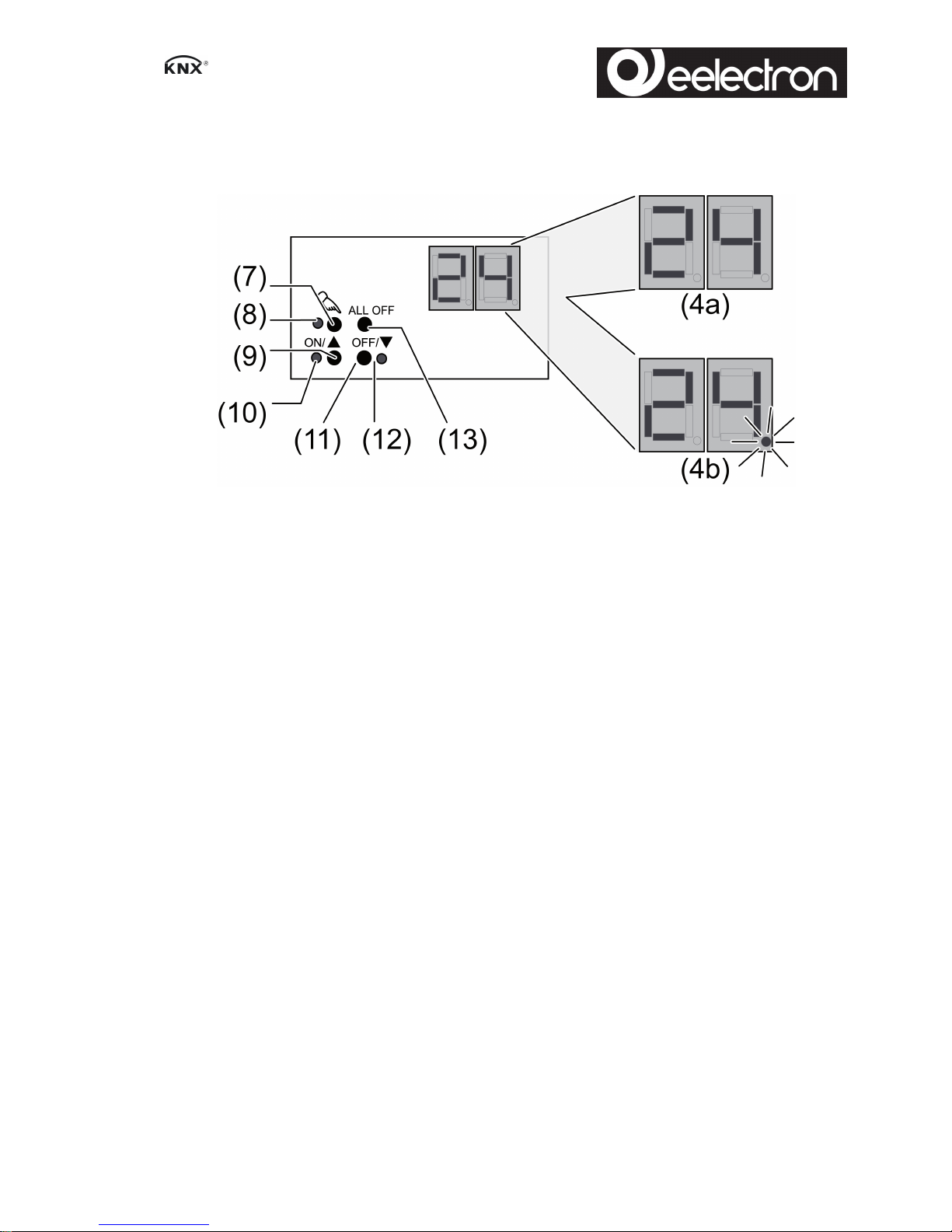
4 Operation
Operating elements
Figure 2
(4) Display of DALI number (1...64)
(4a) DALI group
(4b) Individual DALI devices
(7) Button c – Manual operation
(8) LED c – On: Continuous manual mode active
(9) ON/nbutton – switch on or increase brightness
(10) LED ON/n – On: DALI device or group switched on, brightness 1...100 %
(11) OFF/o button – switch off or reduce brightness
(12) LED OFF/o – On: DALI device or group switched off, brightness 0 %
(13) ALL OFF button – Switch off all DALI devices
In operation with the button field the device distinguishes between a short and a long press.
- Short: pressing for less than 1 second
- Long: Pressing for between 1 and 5 seconds
Operating modes
- Bus operation: Operation via push-button sensors or other bus devices
- Short-term manual operation: Manual operation locally with button field, automatic return to
bus operation.
- Continuous manual mode: Exclusively manual operation on the device
i No bus operation is possible in manual mode.
i No manual mode is possible in case of bus failure.
i After a bus failure and restoration the device switches to bus operation.
i After a power failure and restoration the device switches to bus operation.
i The manual mode can be disabled in ongoing operation via a bus telegram.
Switching on the temporary manual control
Operation using the button field is programmed and not disabled.
o Press the c button briefly.
Display (4) shows 01, LED c remains off.
- or Display (4) shows bc: all connected DALI devices are controlled jointly.
3/9
IC00P01DAL - DALI gateway
 Loading...