

Eela Audio D4 Operating Manual
eela audio
OPERATING MANUAL
D4
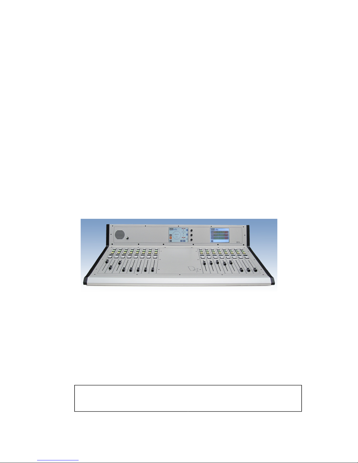
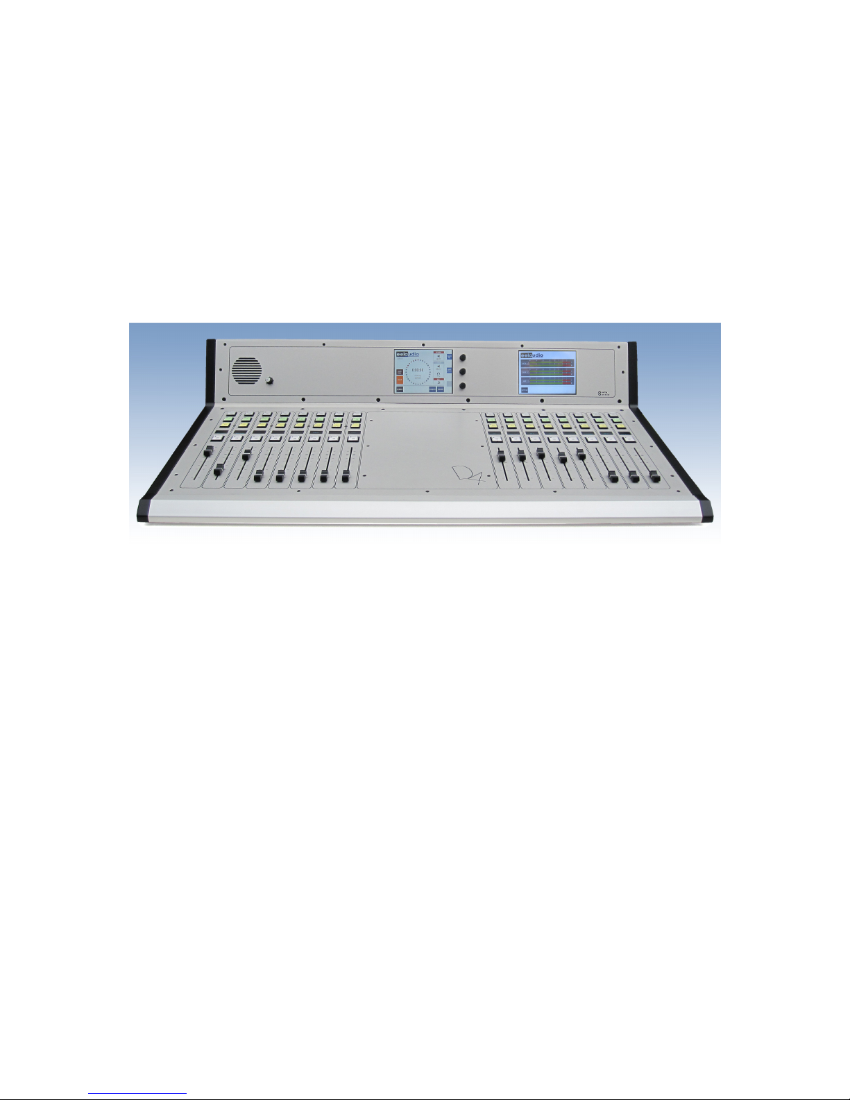
D4
Broadcast mixing desk
EA Broadcast / Eela Audio, Het Riet 8 A, 5431NM Cuijk, The Netherlands
http://www.eela-audio.com e-mail: sales@eela-audio.com

Thank you for the purchase of this
D4 digital mixing desk
. First read this manual carefully before
starting to use the apparatus. Please keep this manual so you can refer to it at a later stage.
Functions and / or layout of the touch screen of the D4 can vary due to different software versions.
More information is available on http://www.eela.nl/D4TI
GENERAL REMARKS:
The D4 is designed in a way that most of the functionality is self-explaining and easy to understand by
the experienced radio studio operator.
Due to the flexibility and multi purpose nature of the unit some settings need extra attention
especially the setup of hybrid connections and the integration in an automated environment.
Software version 1.xx
INDEX
Connections 4
System overview 5
Control surface 5
System settings 7
Monitors 8
System 10
Main screen and Login 12
Universal contacts 14
Meters 15
Channel settings 18
Cleanfeeds, N-1, foldback, outside source return, cough signal 21
Setup examples, Control room microphone, studio microphone, hybrid setup 23
GPIO pinout 26
General specifications 27
This product is in conformity with the requirements of the CE directives.
Eela Audio D4 manual
2
Eela Audio D4 table top digital mixing console:
Quick start manual
All digital "universal" broadcast mixing console with 32 + 4 inputs, 16 input faders and 2 touch screen
color displays and a total of 16 outputs. This is sufficient for most modern radio applications:
APPLICATIONS:
The Eela Audio D4 is designed for use in modern radio and television broadcast applications for On-Air
and or production studios.
Digital mixing console, rugged mechanical construction
32 (+4) inputs, 3 main outputs, 10 configurable stereo outputs
16 input faders with ‘Channel On, Start’ buttons
Color touch screen for settings, E.Q., dynamics, configuration
Separate color touch screen for meters
OLED display with status information and input meters
Broadcast audio and logical functions
Extra internal TDM bus for future or 3th party expansion
Eela Audio D4 manual
3
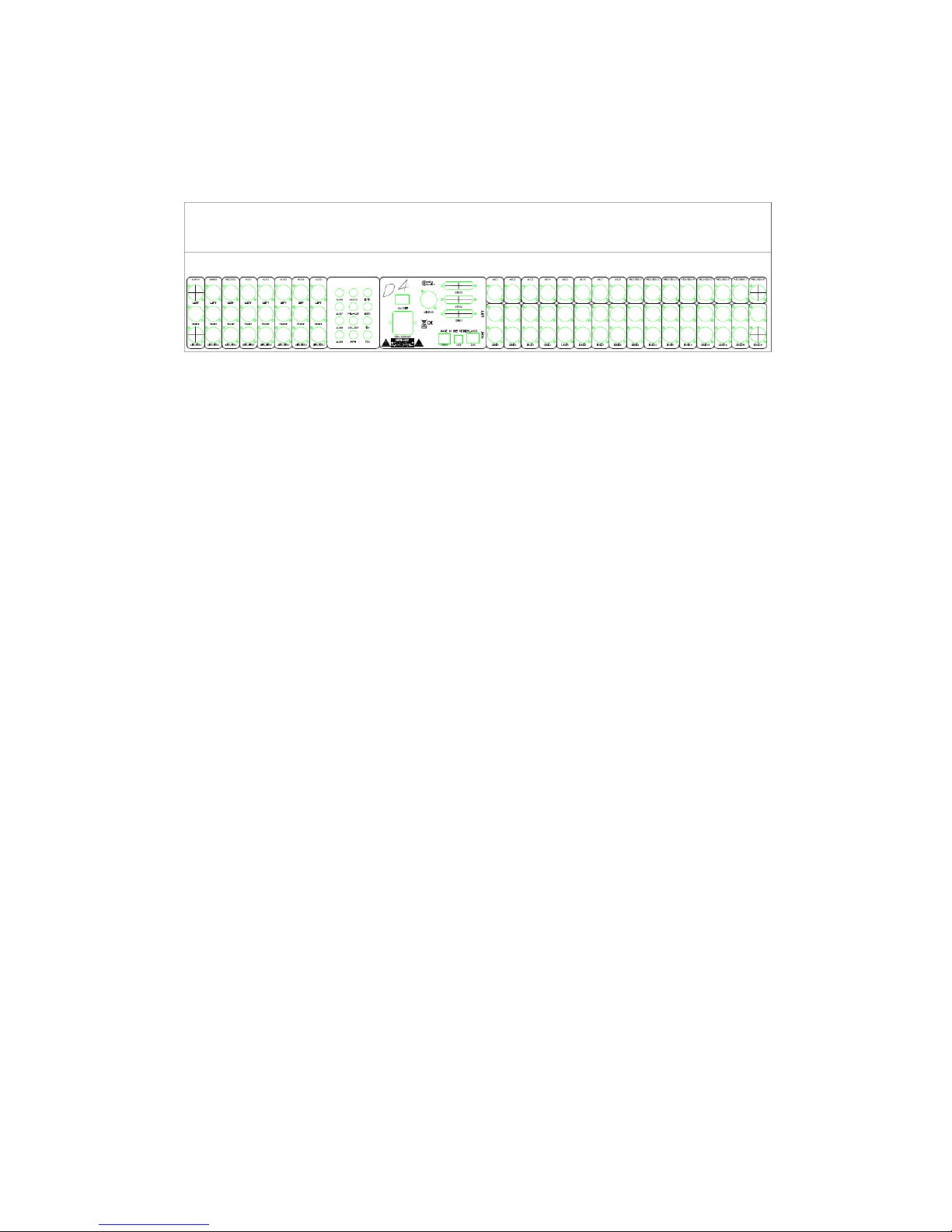
CONNECTOR PANEL:
All connections to and from the mixing desk are concentrated on the back. The main analogue and
digital audio connections are balanced on XLR-type connectors. The connections for monitoring and
AUX 6 – 10 are stereo, unbalanced on 6,3 mm jack.
Connections:
All connections to and from the mixing desk are “industry standard”:
Inputs:
Microphone, AES/EBU balanced XLR female Pin 1 gnd; pin2 +; pin3 –
Line inputs, balanced L and R XLR female Pin 1 gnd; pin2 +; pin3 –
Outputs:
Main analog outputs L and R balanced XLR male Pin 1 gnd; pin2 +; pin3 –
Main digital AES/EBU outputs balanced XLR male Pin 1 gnd; pin2 +; pin3 –
Aux 6..10 unbalanced 6,3 mm jack Tip left; ring right; sleeve gnd
Monitor loudspeaker unbalanced 6,3 mm jack Tip left; ring right; sleeve gnd
Headphones 6,3 mm jack Tip left; ring right; sleeve gnd
TB1 and TB2 6,3 mm jack line inputs to connect an amplified TalkBack microphone or
interfacing with 3rd party intercom systems.
LAN RJ45 connector for future use
D25 multipin connectors for general purpose input and output switches
DBUS RJ45 connector for expansion units like:
The EA963, a 19” 1U A rack unit with and additional 2 x 8 GPI/O contacts as well as 4 solid state AC
relays for switching lamps.
USB standard connector to connect to a computer for firmware updates and control by automation
software like CAPS2.
8 balanced microphone inputs with individually switched 48 Volt phantom powering.
8 AES/EBU balanced digital inputs with sample rate converters range: 22kHz.> 200 kHz
16 balanced analogue inputs.
8 balanced analogue outputs, 2 main outputs, 1 record output, 5 aux.
8 AES/EBU outputs 48 kHz sample rate
5 unbalanced aux outputs
Loudspeaker headphones output unbalanced
External monitor inputs, Talkback inputs unbalanced on 6,3 mm jack
MIO connector, future or 3
th
party expansion for multichannel USB audio or network audio
Eela Audio D4 manual
4
SYSTEM OVERVIEW
CONTROL SURFACE
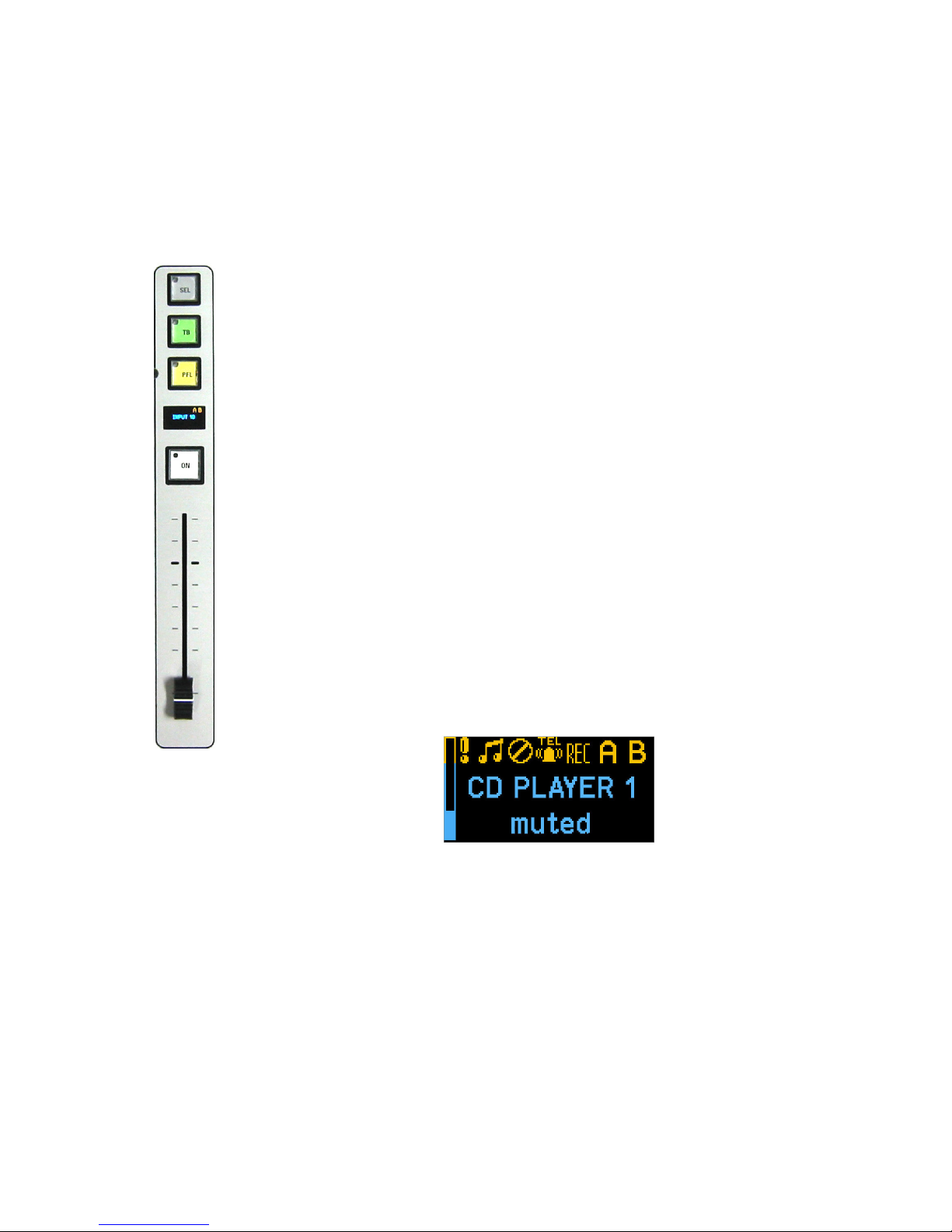
16 Channel input faders each with 4 pushbuttons with LED and OLED display:
Selecting the top grey button opens the channel window in the touch screen
display. The red LED in the left top corner of the button will lit indicating the
channel control and information is displayed in the main screen.
The TB button is only active for TalkBack if an output aux is coupled to this
channel. Pressing this button short the function toggles on or off, holding down
the knob (> 1 sec) it will switch off as soon as you release it. See further on in
this manual to setup a system.
The yellow button is PFL, pre fade listening, the LED indicates an active state.
PFL can be mixed or individual.
White button is the ‘START’ button and LED. This function can be activated in
the ‘settings’ menu of each channel. If active the LED will blink if pressed
indicating a ready status, faderstart command will be fired upon opening of a
fader. Or the other way round, the LED will blink fast upon opening of the fader
and the faderstart command will become active after pressing the ‘start’ button.
A steady LED indicates the active state of the faderstart. If ‘BTN start’ in the
settings menu is not selected the start command is the normal faderstart and
the LED is steady lit upon opening of the fader.
This LED will blink slowly if an external MUTE signal is applied.
The functions of the OLED displays above each fader:
On the left of the OLED is a meter bar that gives you an indication of the input
level,
Symbols indicate the status of the channel,
- The exclamation mark is visible in the case of an input overload.
- The music note indicates “signal present”
- “TEL” indicates that the channel is programmed as a telco input /
output.
- “REC”, “A” and “B” are the outputs the signal is routed to.
Of course the name of the channel is displayed and the bottom line displays
additional status information.
Eela Audio D4 manual
5
Meterbridge controls:
Pfl speaker and volume control on the left hand side Meter display on the right.
Main control screen in the middle:
3 Rotary / selectors for use in conjunction with the touch screen. The function of these rotaries will
dynamically change. The momentary function is displayed in a colored box on the right hand side of
the screen. The color and icon in this box changes with the function.
Touching a volume bar or settings box the background changes color and you can adjust with the
help of the appropriate rotary. Volume bars turn white and a change is momentary executed. The
backgrounds of the setting boxes turn yellow and you can change the setting with the rotary. You
have to confirm the change by pushing on top of the rotary.
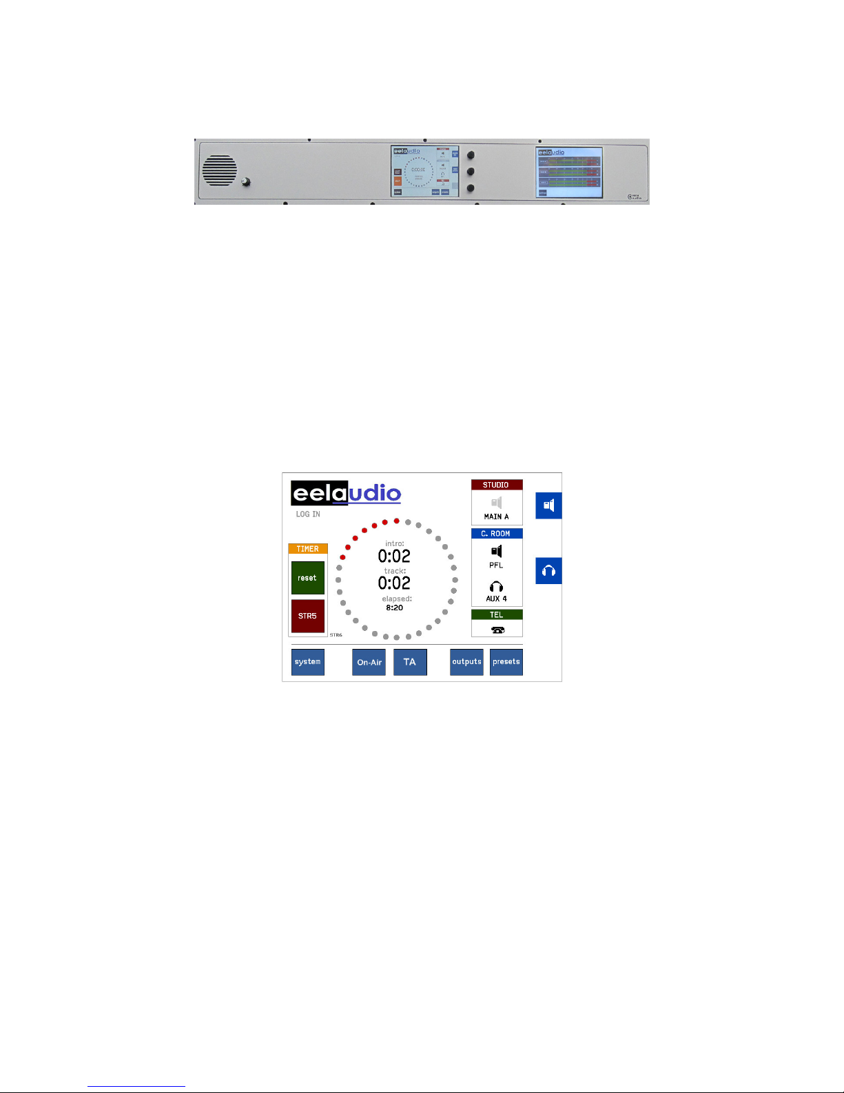
MAIN SCREEN:
In the main screen you can operate the built-in timer. On the right hand side are the icons for control
room monitor loudspeakers and headphones, here indicating that the rotary next to it operates as
volume control for the speakers and phones. Below this icon you see the name of the selected source.
The “TEL” icon will tell you one or more hybrids are off-hook by showing a lifted headset.
The main screen has 2 extra buttons “On-Air” or “TA” each coupled to a GPO and a GPI. These can be
used for signaling and as standard switches or operated in a ‘handshake’ mode.
Eela Audio D4 manual
6
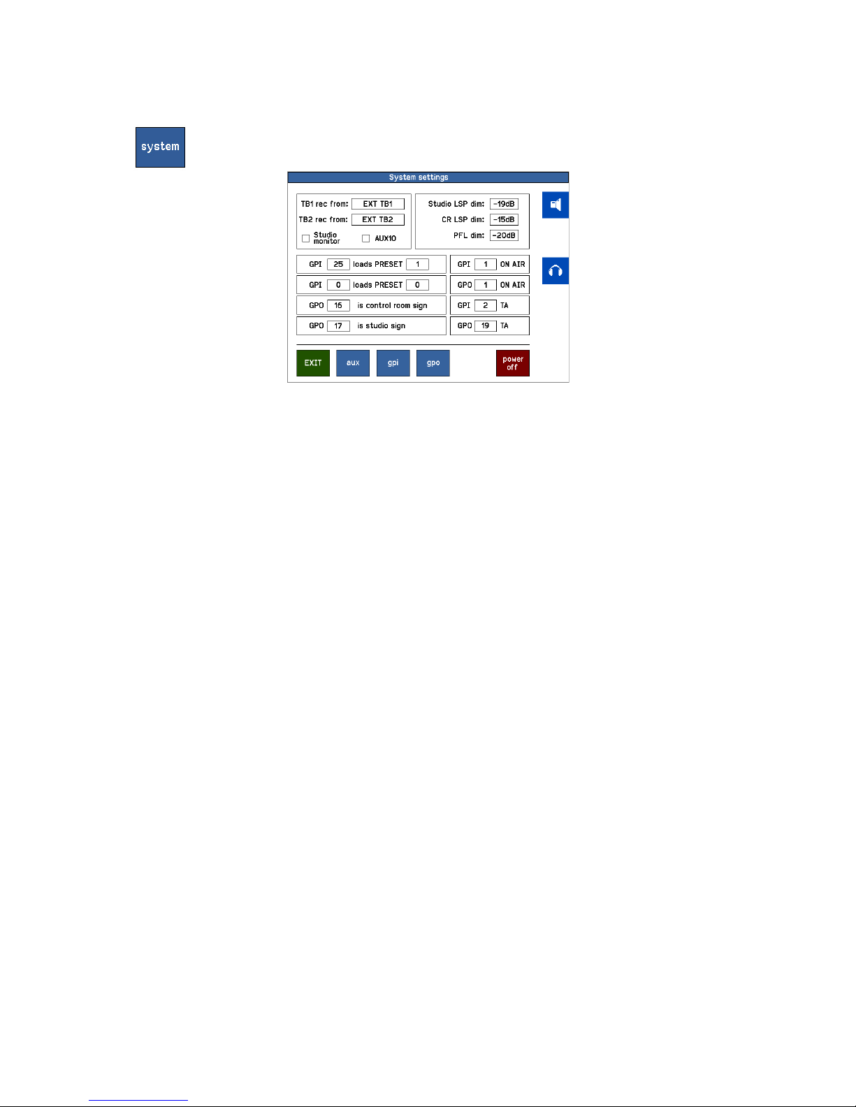
SYSTEM
The ‘system’ button in the main screen will open the system settings menu:
To change touch the number in the box, this will turn into yellow background, next to the bottom
rotary a yellow field appears. Turn the rotary to change the input and confirm this by pushing the
rotary switch. Note that the other two rotaries will stay active for monitor and headphones volume
control.
‘TB rec from’ Select the microphone input which is used for talkback, in many cases the DJ
microphone above the mixing desk. Or you can also choose the TB1 or TB2
inputs on the back.
‘Studio Monitor’ If applicable AUX10 can be used as a studio monitor / foldback. In that case an
icon will appear in the monitor section to select a source and the associated logic
is applied. If your setup is used without a separate studio you can use AUX10 as
a standard aux.
‘Studio LSP dim’ The studio foldback loudspeaker can be set to dim upon opening a fader that is
configured as a studio microphone. The amount of decrease in volume can be
set here.
‘CR LSP dim’ The control room monitor loudspeaker can be set to dim upon opening a fader
that is configured as a control room microphone. The amount of decrease in
volume can be set here.
‘PFL dim’ The pre fade listening loudspeaker can be set to dim upon opening a fader that is
configured as a CR microphone. The amount of decrease in volume can be
set here.
‘GPI loads PRESET’ External contacts, GPI inputs, can be used to load a preset, e.g. controlled by an
automation system.
‘GPO is...” Control room sign or Studio sign, selects the output contact that controls the
control room or studio “ON-AIR” lamp. This can be one of the 24 internal
contacts or a solid state relays in the EA963 expansion box.
“ON-AIR, TA’ GPIO contacts assigned to the universal buttons “On-Air” and “TA”
If you do not assign a GPO – GPO set to ‘0’ - an incoming signal (GPI) will turn
the color of the button into red.
Eela Audio D4 manual
7
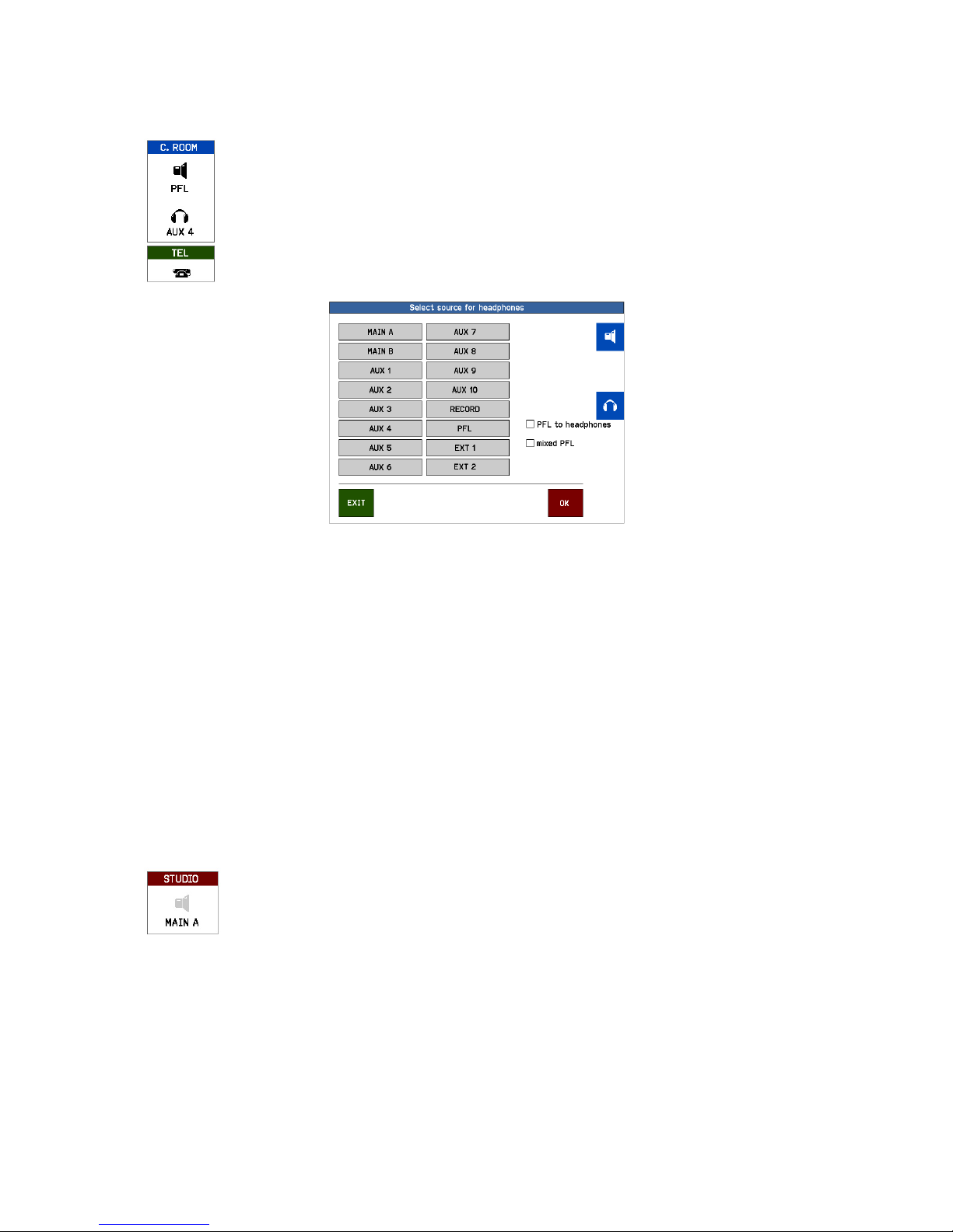
MONITOR
Both Control room loudspeaker, headphone and studio icons hide a source
selector. You can select the source for the monitor speakers and the
headphones by touching the icons and the source selector will open. A selected
source is immediately executed.
The name of the source is displayed underneath the icon.
Source selector for speaker / headphones
In addition you can touch the check-boxes in the monitor select screen for the other functions:
‘PFL to LSP’ routes the PFL signal to the main monitor speakers if a PFL button of one of the
modules is active and replaces the selected monitor signal.
‘PFL to headphones’ routes the PFL signal to the main monitor speakers if a PFL button of one of the
modules is active and replaces the selected headphones signal..
‘Mixed PFL’ Standard pfl switches are mutually releasing. Check this box to mix the pfl
signals.
Note: if mixed PFL is used Talkback becomes active for all channels in PFL mode that have an AUX
coupled to them! See ‘TB output channel’ in CHANNEL SETTINGS
STUDIO MONITOR
The ‘STUDIO’ icon is only visible if AUX10 is assigned as studio monitor; see
‘System settings / ‘Output select’
You can select the source for the studio monitor speakers by touching the icon
and the source selector will open.
The name of the source is displayed underneath the icon.
Note: You can program any aux to follow the dim and TalkBack function of a studio foldback but
without the choice of selecting different outputs, see paragraph below.
Eela Audio D4 manual
8
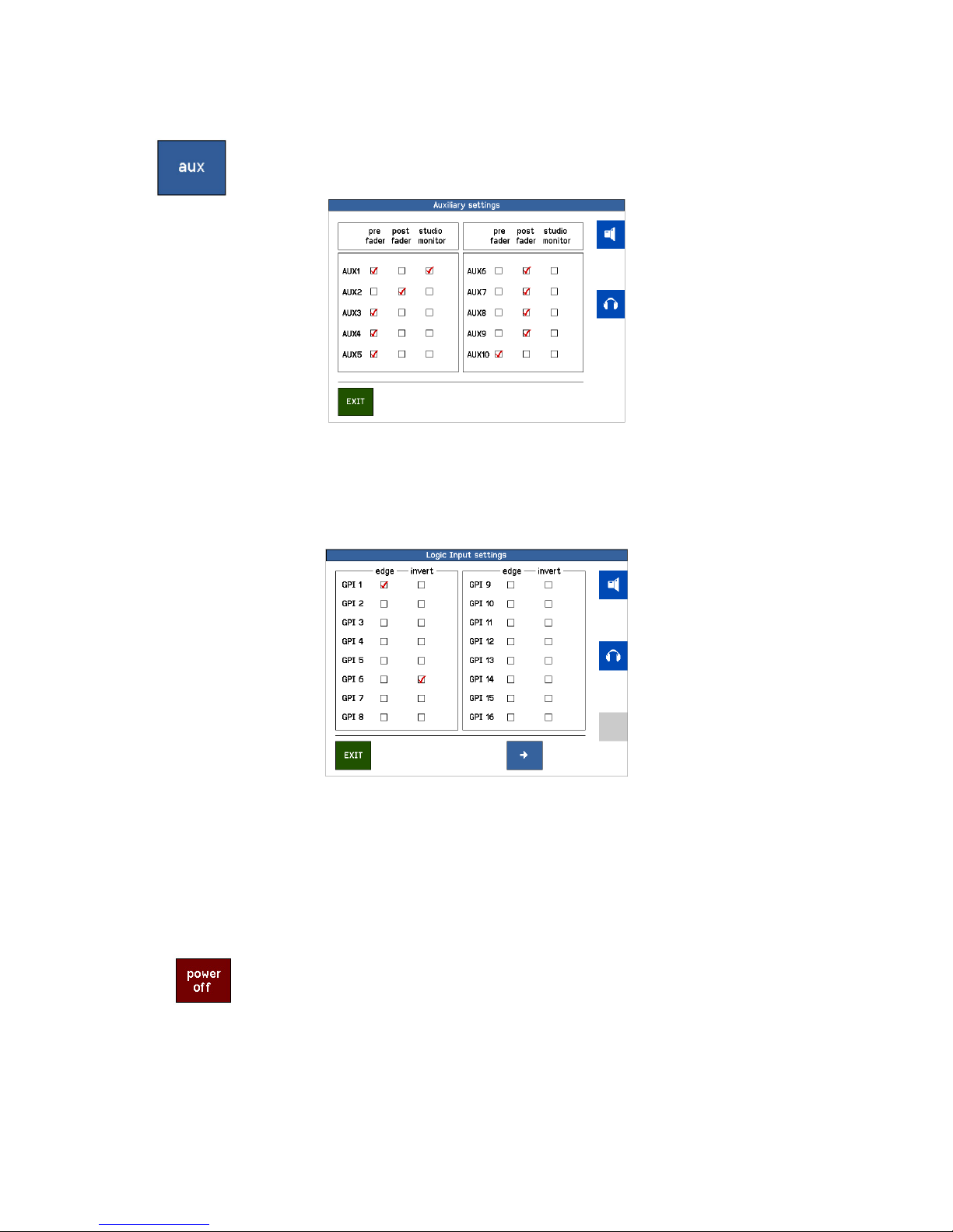
SYSTEM
Master auxiliary settings menu sets the AUX for ‘Pre’ or ‘Post’ fader.
If a Studio monitor check box is active the Studio monitor DIM function is
applied to this AUX upon opening a “Studio Microphone” fader.
‘GPI’ and GPO’ Here you can also set the type and shape of the GPIO’s: pulse (edge) or
continuously, inverted or not….
You can step trough the pages for the settings of the GPI and GPO 1 to 24 on
the D25 connectors on the back and for 25 onwards on an EA963 extender unit.
The same applies to the General Purpose Outputs.
NOTE THAT AN INVERTED GPI WILL BE ACTIVE WHEN NO CONNECTION IS MADE!! E.g. if you have
assigned a GPI to an input mute that channel will be muted if the switch is not connected!
If set to “EDGE” the GPI signal will toggle the function ’on’ on the first pulse and ‘off’ on the second.
Software power off, the D4 will stay in stand-by mode.
The unit has a hardware power switch in the back. It is recommended to use this
switch to shut off the unit. If the unit is mounted in a table were you cannot
reach this switch you can shut down (sleep mode) the unit in software.
By holding down the ‘settings’ rotary for 3 seconds the unit will power up again.
Please note: From this state the unit will also switch on if the (mains) power was
down and switched on again!
Eela Audio D4 manual
9
 Loading...