

EEJohnson 5100 series Quick Reference Manual
ANALOG/DIGITAL PORTABLE
QUICK
REFERENCE
GUIDE
5100 S
ERIES
PORTABLE RADIO
■
APCO Project 25
– Conventional
–
Trunked
■
SMARTNET®/
SmartZone
®
■
Analog FM
Conventional
VHF
UHF
800 MHZ
Part No.002-5100-015
7-04hph Printed in U.S.A.
3. Press the F2 button to select the highlighted parameter. The available
modes for that parameter are then displayed and the currently selected
mode is indicated by an asterisk.
4. Press the Up/Down button to highlight the desired mode. Then press the
F2 key to select that mode.
5. To step back to the previous menu level or exit the menu mode, press
the F1 (Clear) key.
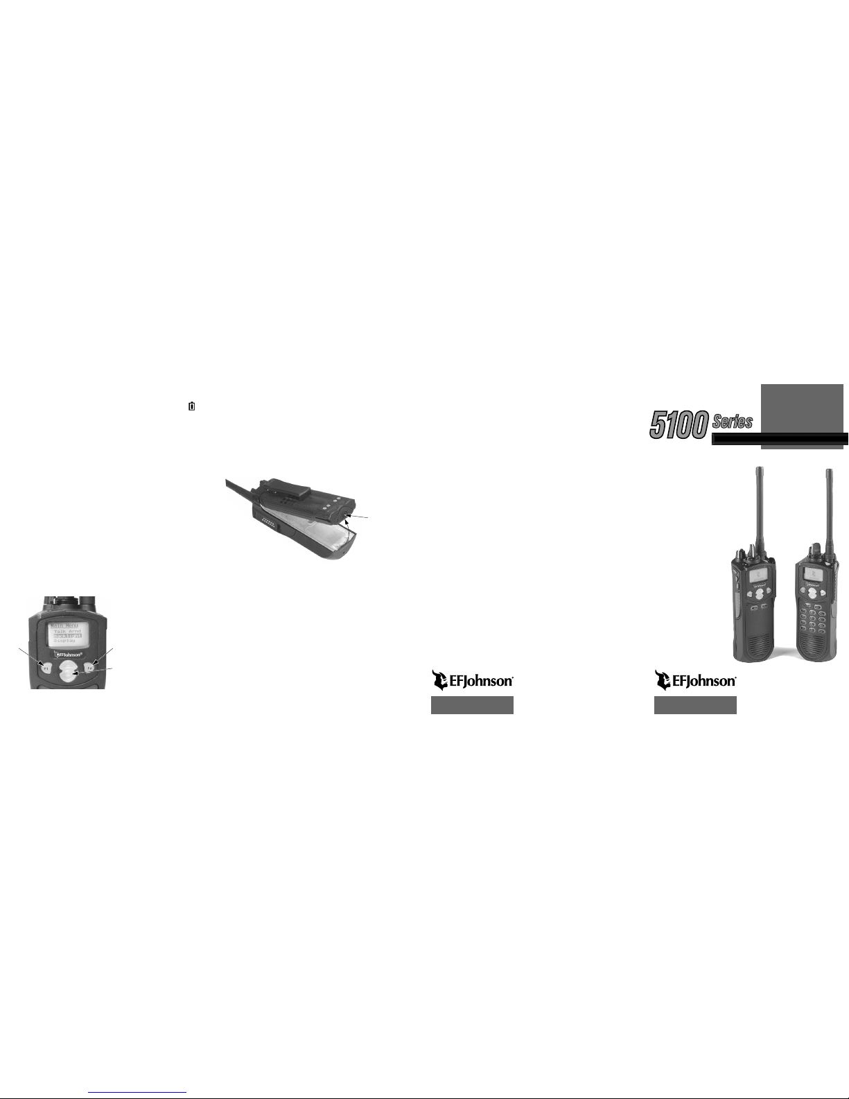
BATTERY REMOVAL / INSTALLATION
To remove the battery from the radio for recharging or replacement,press
the release button (see illustration below) and then rotate the battery
upward to the approximate point shown and
withdrawn it from chassis.
RECHARGING
WARNING: Do not incinerate
a battery pack because it may
explode. Also, do not short circuit the
terminals because the battery pack and the object causing the short may
become very hot. Do not disassemble or modify a battery pack.
If the battery is recharged while attached to the radio, be sure to turn radio
power off. If power is left on, the battery will begin to slowly discharge
when the charger enters the trickle mode (indicated by a green indicator).
This occurs because the charge current in this mode is less than standby
radio current. Power should also be turned off to prevent charger damage
(see Caution which follows). CAUTION: Do not transmit in close prox-
imity to the charger because charger damage may result. Note that transmissions may occur automatically in the trunked modes.
When the battery fails to hold a charge or provides only a very short operating time, it must be replaced with a new unit. A fully charged battery
provides approximately 13 hours of service before recharging is required.
This time may be less if more than 5% of the time is spent transmitting or in
the unsquelched receive mode, or if the battery is not fully charged or its
capacity has deteriorated. Dispose of the nickel metal-hydride (NiMH)
battery pack used in this radio in accordance with local waste regulations.
LOW BATTERY INDICATION
When the battery discharges to the point where recharging is required, the
icon is displayed. The battery should be recharged or replaced as soon as
practical after this indication appears. Additional low battery indications
that may be programmed include a beep that sounds every minute, another
that sounds when the PTT switch is pressed, and/or a top panel indicator
that flashes red every 30 seconds.
OPTION BUTTONS
Almost all the buttons on this transceiver are programmable unless they are
dedicated to a specific function. The programmable buttons are as follows:
• On the side panel, the three buttons above the PTT switch.
• On the top panel, the orange button and rotary three-position switch.
• On the front panel, F1 and F2 if the menu mode is not used (see next
section), and F3 and F4.
• With DTMF keypad models, all 12 DTMF keys (0-9,
#
,*).
Each option button can be programmed to control a different function in
each of the three operating modes (conventional, SMARTNET
®
/
SmartZone
®
, Project 25 Trunked).
MENU MODE
Many transceiver functions are controlled by the menu mode, an option
switch, or both. Only the functions which apply to the selected channel
type are displayed. The availability of the menu mode and the parameters
that are selectable are determined by system operator programming. The
menu mode operates as follows:
1.Press the F2 key to
select the menu mode.
The selectable menu
parameters are then
displayed below “MAIN
MENU” as shown.
2.Press the Up/Down
button to scroll up or
down through the list
until the parameter you
want to change is highlighted by the bar.
Menu
Exit
Back/
Menu
Select/
Enter
Menu
Scroll
Up/Down
(Continued)
6 7
Battery Release
Button
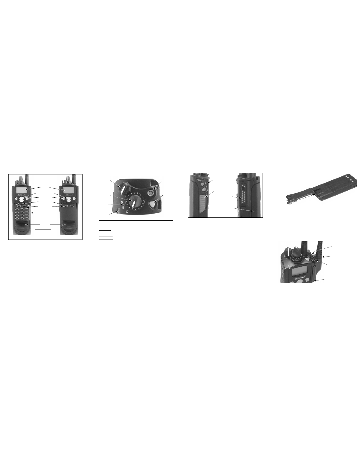
FRONT PANEL CONTROLS
Microphone—The location of the microphone is shown above. For best
results, hold the transceiver 2-3 inches from you mouth and speak at a
normal conversational level.
Display—A graphical LCD (Liquid Crystal Display).
Up/Down Button—Selects zones when multiple zones are programmed.
Also provides up/down select in other modes such as the menu mode.
Pressing the upper part of the button increases the selected number and
pressing the lower part decreases the selected number.
F1—Functions as a Back and Exit button in various modes such as the
Menu Mode. If Menu Mode is not used, this is a programmable option
button.
F2—Selects the Menu Mode and functions as an Enter button. If Menu
Mode is not used, this is a programmable option button.
F3, F4—Programmable option buttons.
DTMF Keypad—The full keypad DTMF models include the 0-9,
*
, and
#
keys which are used to dial telephone, unit ID, group ID, and other numbers.
Speaker—The speaker is located behind this grill. When a speaker/micro-
phone is used, this speaker is automatically disabled.
TOP PANEL CONTROLS
Multi-Function Indicator—Indicates the following conditions:
Stead
y Red–Transmitter keyed (enabled) by pressing the PTT switch on
the side.
Flashing Red–Low battery in receive mode.
Stead
y Green–Signal detected in receive mode.
On-Off/Volume—Turning the knob clockwise turns power on and sets the
volume level. Turning it counter-clockwise to the click turns power off.
Channel Switch—This 16-position switch selects up to 16 channels in the
current zone. Some positions may be unprogrammed in which case a tone
sounds and “UNPROGRAMD” is displayed. Additional zones can be
programmed to allow up to approximately 512 channels to be selected by
this switch.
Rotary Option Switch—This is a three-position switch that can be
programmed to control an option. The “A” position is “on” and the “B” and
“C” positions are “off”. If this switch is programmed to select zones, “A”
selects Zone 1, “B” Zone 2, and “C” Zone 3, if applicable.
Antenna Connector—Connection point for the antenna. Make sure the
antenna is tight before using the radio.
Emergency Switch—This button can be programmed as an Emergency
switch or for other functions. If used as an emergency switch, consult you
system operator to determine how it is used in your radio system.
Display
Up/Down Switch
Option Keys
Microphone
Option Keys
DTMF Keypad
Speaker
DTMF Keypad Model Limited Keypad Model
In Se
veral Modes:
F1 = Exit
F2 = Select/Menu Enable
Emergency
(Option)
Switch
On-Off
Volume
Antenna
Connector
Option
Switch
Channel/
Talk Group
Switch
Multi-Function
Indicator
SIDE CONTROLS
PTT (Push-To-Talk) Switch—This switch is pressed to turn the
transmitter on so you can talk and then released to listen. Transmitting is
indicated when the top panel indicator is red.
Option Switches 1, 2, and 3—Each of these switches can be system
operator programmed to control a specific function.
Battery—Refer to “Battery Removal/Installation” for more information.
Accessory Connector—Connection point for optional accessories such as
a speaker/microphone or earphone. Refer to “Accessory Installation” for
more information.
ZONE AND CHANNEL SELECT
Zone Select—The Up/Down switch is used to change the zone when not
in special modes such as the menu mode. Press the upper part of this
switch to select the next higher number and press the lower part to select
the next lower number. After the highest programmed zone is displayed,
wrap-around to the lowest programmed zone occurs and vice versa.
Channel Select—Channels are selected by the rotary 16-position selector
switch on the top panel. The selected channel number and alias are
indicated in the display. When an unprogrammed channel is selected,
“UNPROGRAMD” is displayed and a tone sounds (if tones are enabled).
Option Switches
PTT Switch
Battery Pack
Accessory
Connector
1
2
3
BELT CLIP INSTALLATION
Remove the battery and slide the belt clip into the slot on the
battery as shown below. To remove the clip, simply
slide it out. It is held in place by the chassis
when the battery is installed on the
radio.
ACCESSORY INSTALLATION
To connect an accessory such as a speaker-microphone to the transceiver,
proceed as follows:
1. Remove the protective cover over the accessory jack on the side of the
transceiver.
2. Insert the hook on the lower end of the accessory connector into the slot
on the side of the transceiver.
3. Rotate the latch open, press the connector against the transceiver,and
then release the latch to lock the connector in place.
4. Install the included locking screw in the latch tab in the location shown.
OPERATING MANUAL
A complete operating manual on a CD-ROM is available for this radio.
Contact your system operator to obtain this manual.
Latch
Install Lock
Screw Here
Accessory Connector
Hook
2 3 4 5
 Loading...