

EEG HD1492
HD Encoder Frame Card
Product Manual
EEG Enterprises, Inc.
586 Main Street
Farmingdale, New York 11735
TEL: (516) 293-7472 FAX: (516) 293-7417
Copyright © EEG Enterprises, Inc. 2018
All rights reserved.

HD1492 HD Encoder Frame Card
Contents
1 Introduction 3
1.1 Product Description . . . . . . . . . . . . . . . . . . . . . . . 3
2 Installation 4
2.1 Rear Modules . . . . . . . . . . . . . . . . . . . . . . . . . . . 4
2.1.1 Single-Width Rear Module . . . . . . . . . . . . . . . . 4
2.1.2 Double-Width Rear Module . . . . . . . . . . . . . . . . 6
3 HD1492 Operation 8
3.1 Front Panel . . . . . . . . . . . . . . . . . . . . . . . . . . . . 8
3.2 DashBoard Menus . . . . . . . . . . . . . . . . . . . . . . . . 8
3.2.1 System . . . . . . . . . . . . . . . . . . . . . . . . . . . 11
3.2.2 iCap™ . . . . . . . . . . . . . . . . . . . . . . . . . . . . 12
3.2.3 Encoding . . . . . . . . . . . . . . . . . . . . . . . . . . 14
3.2.4 SCTE-104 . . . . . . . . . . . . . . . . . . . . . . . . . . 16
3.2.5 TCP/IP . . . . . . . . . . . . . . . . . . . . . . . . . . . 18
3.2.6 CCMatch . . . . . . . . . . . . . . . . . . . . . . . . . . 19
3.3 Web Configuration . . . . . . . . . . . . . . . . . . . . . . . . 20
3.4 Using Smart Encoder Commands . . . . . . . . . . . . . . . . 20
3.4.1 Local Entry Modes . . . . . . . . . . . . . . . . . . . . . 21
3.4.2 Regeneration Mode . . . . . . . . . . . . . . . . . . . . 22
3.5 XDS Insertion . . . . . . . . . . . . . . . . . . . . . . . . . . . 24
4 Additional Features 30
4.1 iCap™ Secure Internet Captioning . . . . . . . . . . . . . . . 30
4.2 Lexi™ Automatic Captioning . . . . . . . . . . . . . . . . . . 32
4.3 Serial Port Configuration . . . . . . . . . . . . . . . . . . . . . 34
4.4 Encoder Status Commands . . . . . . . . . . . . . . . . . . . 34
A General-Purpose I/O 35
B Serial Port Connector 36
C Video/Connector Specifications 37
Copyright © EEG Enterprises, Inc. 2018 1

HD1492 HD Encoder Frame Card
Copyright 2018, EEG Enterprises, Inc. All rights reserved. The
contents of this manual may not be transmitted or reproduced in
any form without the written permission of EEG.
The revision date for this manual is April 3, 2018.
2 Copyright © EEG Enterprises, Inc. 2018

HD1492 HD Encoder Frame Card
1 Introduction
1.1 Product Description
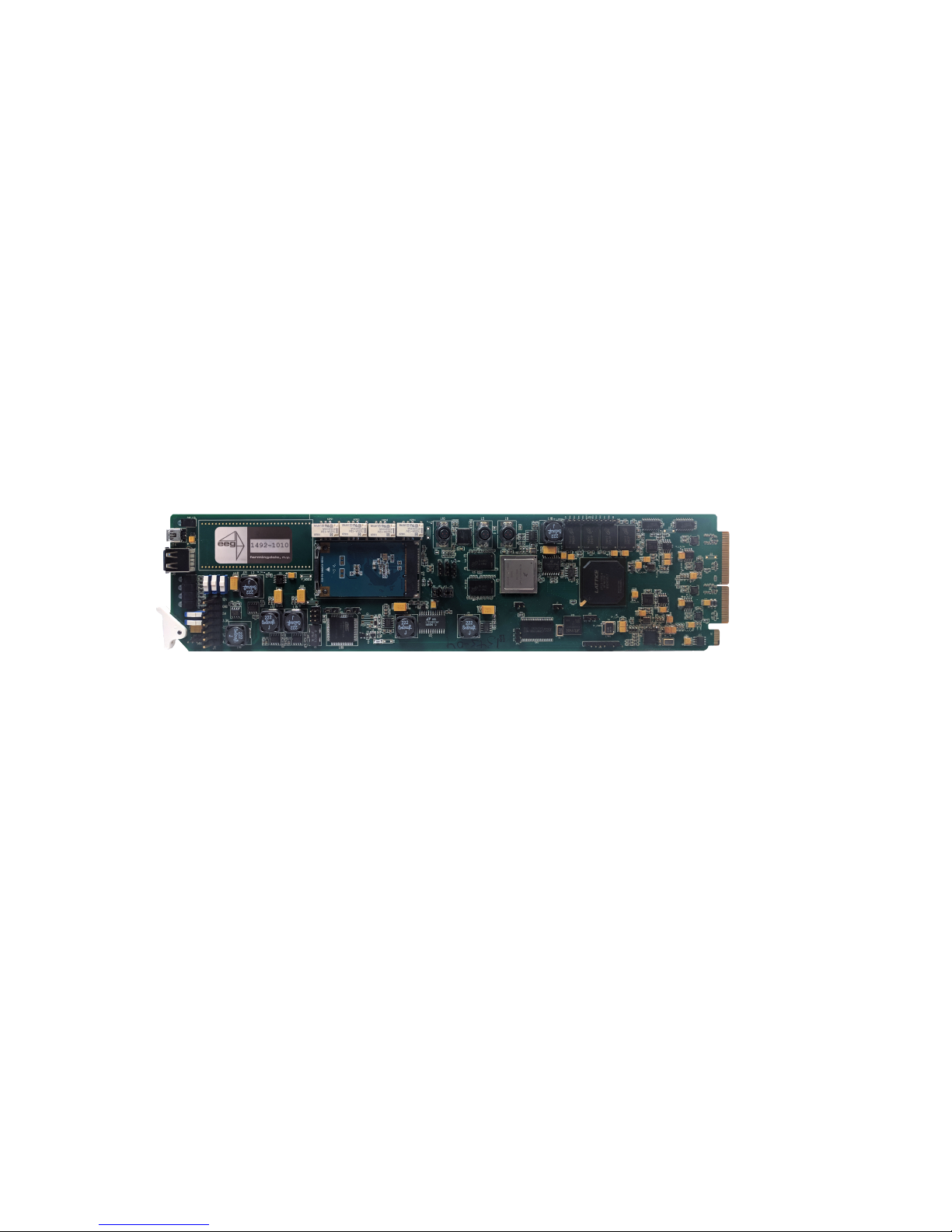
The HD1492 Encoder Card brings the functionality of EEG’s industry
standard Smart Encoder to the openGear®platform, providing closed
captioning and XDS encoding in a single modular frame card operating
on the openGear®platform. The frame card utilizes the user friendly
DashBoard software, which is available for Windows, Mac and Linux operating systems and streamlines setup of the HD1492.
Like the 1RU HD492, the HD1492 streamlines and integrates the Line
21/HD-VANC encoding process into one powerful solution, supporting a
wide variety of powerful ancillary data software on-board. The HD1492
includes connection software for EEG’s iCap™ Realtime Captioning System, and in combination with the ComCC-1250 card can provide an unprecedented level of reliable and redundant connectivity solutions.
3
HD1492 HD Encoder Frame Card
2 Installation
2.1 Rear Modules
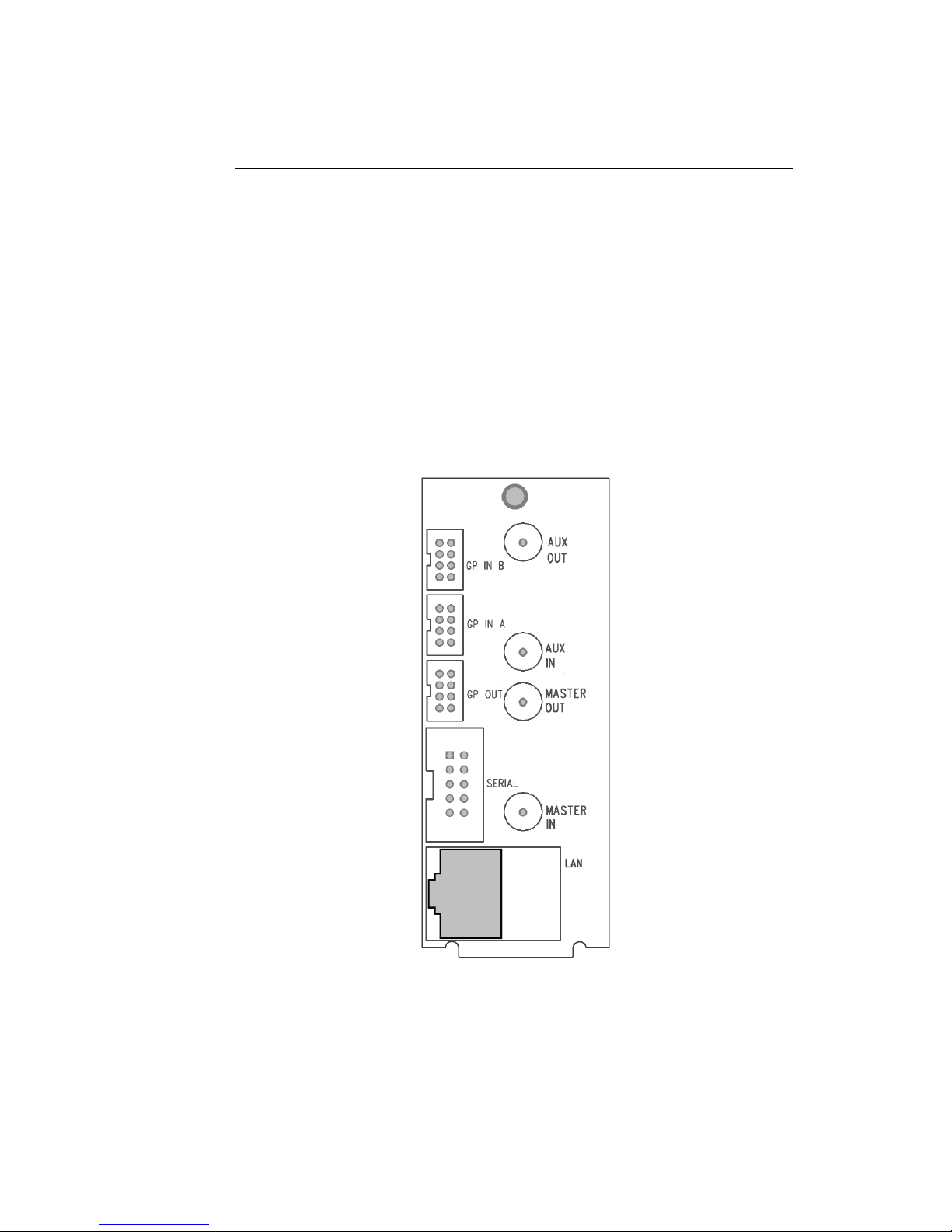
There are two back panel configurations available for the HD1492. The
single-width rear panel is shown here, followed by a guide to the connectors it contains.
2.1.1 Single-Width Rear Module
4

HD1492 HD Encoder Frame Card
MASTER IN Master video input. Accepts SMPTE 259M
SD–SDI, SMPTE 292M HD–SDI, or SMPTE
424M 3G–Level-A SDI.
AUX IN Auxiliary video input. Can be used as a
source of caption data when connected to
a captioned 3G–SDI, HD–SDI, or SD–SDI
video source. Caption data from the Aux
Video In will be up-converted or downconverted as necessary for encoding onto
the Master Video signal. If caption data is
present at both the Master Video In and the
Aux Video In, the signal with HD data will
take precedence.
MASTER OUT Program video output with relay-bypass
protection.
AUX OUT Auxiliary video output with relay-bypass
protection.
GP IN A and GP IN B Two Molex 87831-0841 connectors, each
containing 4 GPI inputs. See Appendix A for
more information regarding GPIO usage.
GP OUT Molex 87831-0841 connector containing 4
GPI outputs. See Appendix A for more information regarding GPIO usage.
SERIAL Connector for cable containing two DB–9
(RS-232) serial ports labeled P1 and P2.
Both serial ports can be used as inputs for
configuration.
LAN 1000-Base Ethernet port for connection to
LAN. After configuring your HD1492’s network settings in DashBoard (see below),
you can view the Web Configuration site for
your card by navigating to its local IP address in your web browser.
5

HD1492 HD Encoder Frame Card
2.1.2 Double-Width Rear Module
The double-width rear module provides a modem connector, in addition
to the I/O included on the single-width rear module, and takes up 4 card
slots in the openGear®frame, instead of 2.
6

HD1492 HD Encoder Frame Card
IN1 Master video input. Accepts SMPTE 259M
SD–SDI, SMPTE 292M HD–SDI, or SMPTE
424M 3G–Level-A SDI.
IN2 Auxiliary video input. Can be used as a
source of caption data when connected to a
captioned HD–SDI or SD–SDI video source.
Caption data from the Aux Video In will be
up-converted or down-converted as necessary for encoding onto the Master Video
signal. If caption data is present at both the
Master Video In and the Aux Video In, the
signal with HD data will take precedence.
OUT1 Program video output with relay-bypass
protection.
OUT2 Auxiliary video output with relay-bypass
protection.
GPIN A and GPIN B Two Molex 87831-0841 connectors, each
containing 4 GPI inputs. See Appendix A for
more information regarding GPIO usage.
GP OUT Molex 87831-0841 connector containing 4
GPI outputs. See Appendix A for more information regarding GPIO usage.
RS232 Connector for cable containing two DB–9
(RS-232) serial ports labeled P1 and P2.
Both serial ports can be used as inputs for
configuration.
LAN 1000-Base Ethernet port for connection to
LAN. After configuring your HD1492’s network settings in DashBoard (see below),
you can view the Web Configuration site for
your card by navigating to its local IP address in your web browser.
Modem Standard phone jack data port. Connect to
a phone line to enable dial–up captioning.
This feature is optional on the HD1492.
7
HD1492 HD Encoder Frame Card
3 HD1492 Operation
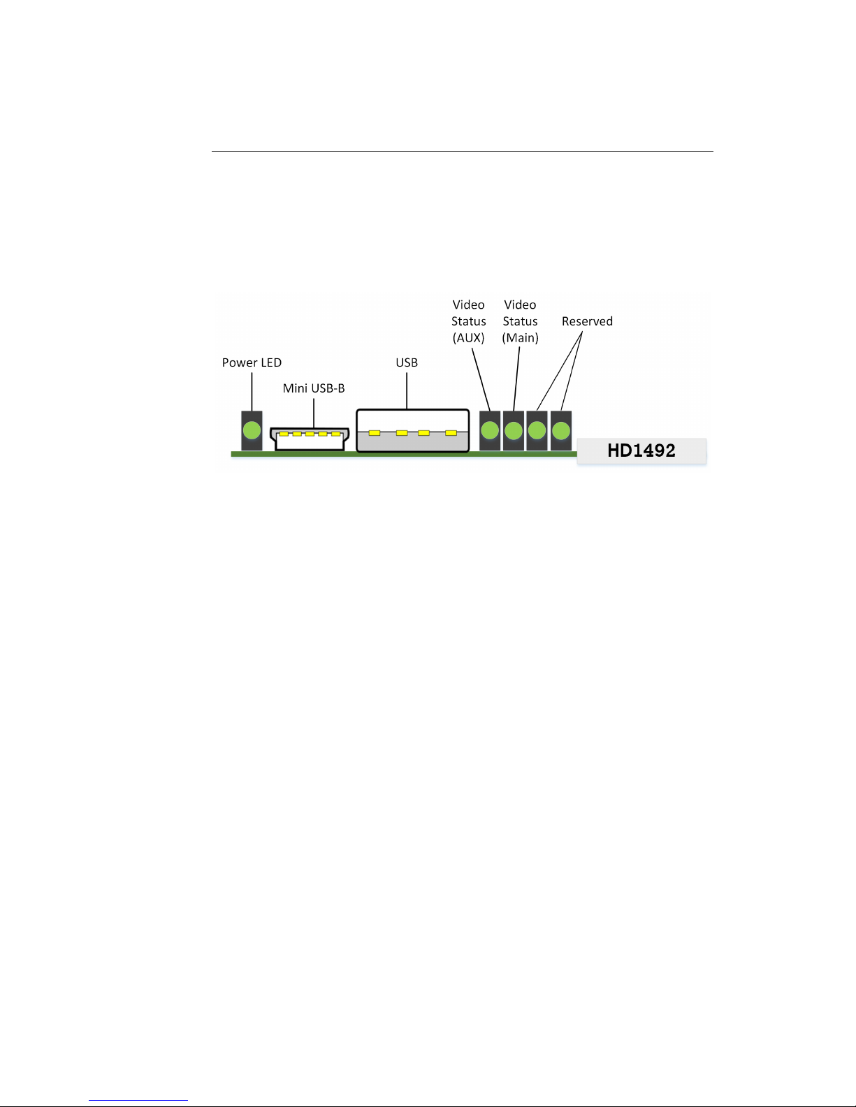
3.1 Front Panel
The front of the HD1492 card is depicted in the following diagram:
Power LED The power LED will be green when the
card is receiving power from the frame.
USB Connectors Reserved for future use.
Video Status (AUX) This LED will be off when there is no
video present on the auxiliary input.
When HD or 3G video is present, it will
be green, and when SD video is present,
it will be orange.
Video Status (Main) This LED will be red when there is no
video present on the main input. When
HD or 3G video is present, it will be
green, and when SD video is present, it
will be orange.
3.2 DashBoard Menus
The DashBoard software is used to configure encoder settings, networking, and perform additional basic configuration for the frame card. It
can be downloaded from Ross Video: https://www.rossvideo.com
Once you have successfully installed the DashBoard tool, open the program to find information about the HD1492 and to configure your card.
8
HD1492 HD Encoder Frame Card
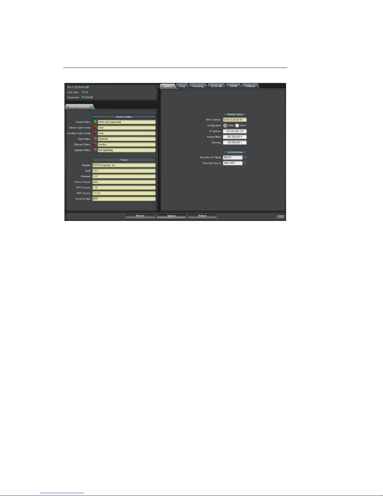
There are two main sections in the DashBoard interface: the Status information on the left side and the Setup menu on the right side. At the
bottom of the interface, you will find the Upload button, which can be
used to upgrade your HD1492’s DashBoard interface firmware, and the
Reboot button, which can be used to reboot your HD1492.
The upper section on the left shows the Card State and the Connection
status, each of which has an indicator light and description of the card’s
status. There is a more detailed tab labeled Status Information below
the two basic indicators that provides information about the card’s version and its current setup configurations.
The System Status section shows what video types are present and
the current status of the Ethernet connection. Output Status displays
the mode that the encoder is operating in; the icon will be green when
the unit is in active operating mode and will be red when the Encoder
is in Relay Bypass mode. Master Input Format displays the video type
detected on the master video input, including format information for HD
video, while Auxillary Input Format indicates the video type detected on
the auxillary video input, including format information for HD video. The
Upgrade Status field displays information about whether the encoder is
9

HD1492 HD Encoder Frame Card
currently loading an upgrade.
The lower section entitled Product displays identifying information about
the hardware and software versions of the card. This section displays
the supplier, the build number, the firmware number, and the ASW version to identify the software installed and the serial number of the card.
The setup section in the right half of the tool is broken up into multiple tabs: System, iCap, Encoding, SCTE-104, TCP/IP, and CCMatch.
Note that the SCTE-104 and CCMatch tabs will only be present if your
HD1492 has been licensed to use the respective software modules.
10
HD1492 HD Encoder Frame Card
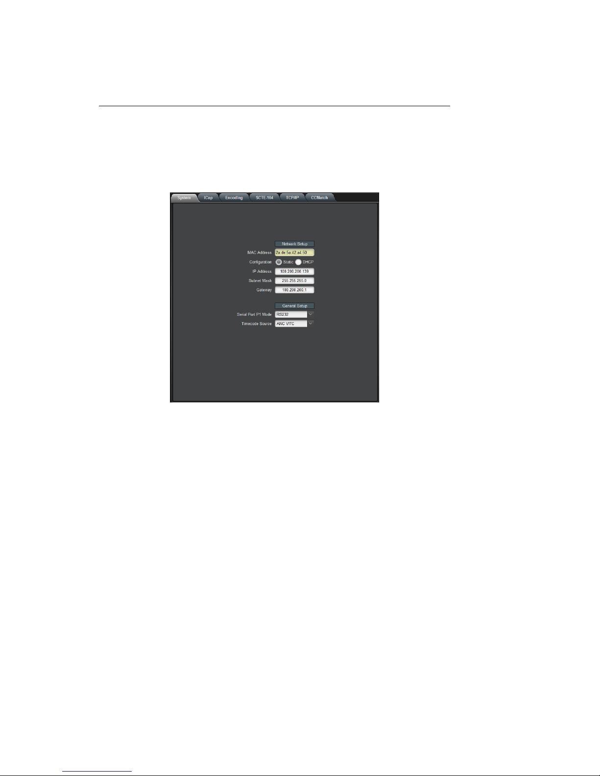
3.2.1 System
The System tab contains network configuration and general setup fields.
MAC Address Displays the encoder’s MAC address.
Configuration Selects between static and DHCP network
settings.
IP Address Selects the IP address the unit will be as-
signed on your LAN (read-only in DHCP
mode).
Subnet Mask Selects the bit mask used; this should
match the mask used on your LAN (readonly in DHCP mode).
Gateway Selects the address of the device that the
unit will use to communicate outside of
your LAN (read-only in DHCP mode).
Serial Port P1 Mode Selects the signaling mode used by the P1
serial port; options are RS-232, Sony-style
RS-422, and EEG-style RS-422.
Timecode Source Selects the timecode source for any appli-
cations requiring it; options are ANC VITC,
DVITC Master, and DVITC Aux.
11

HD1492 HD Encoder Frame Card
3.2.2 iCap™
The iCap™ setup menu allows configuration and monitoring of audio for
iCap™.
Audio Group Selects the SDI embedded audio channel group
that the iCap™mix is sourced from. Up to 4
channel groups can be carried on an SDI signal, though most commonly Group 1 carries the
primary audio program.
Audio Mix Selects whether the iCap™ mix is being cre-
ated from a Stereo or Surround channel group.
Choose “Stereo” to select a mix of the left and
right channels (1 & 2 or 3 & 4 within the selected Audio Group, according to the Stereo
Pair setting), or “Surround” to select a mix of
the left, right, and center channels (1, 2 & 3
within the selected Audio Group).
Stereo Pair Selects whether the iCap™ stereo mix is being
created from channels 1 & 2 or channels 3 & 4
within the selected Audio Group.
12

HD1492 HD Encoder Frame Card
Input Level Adjustment (dB)
Adjusts the audio input level without adjusting
the output level of your source. The built–in
digital input trim can boost or cut the audio input level by as much as 12 dB.
Peak Level (%) Dynamically displays the peak signal level at
the audio input. For optimal sound quality, the
peak level should reach at least 60% across the
screen.
13

HD1492 HD Encoder Frame Card
3.2.3 Encoding
Various aspects of the operation of your encoder can be configured here.
Insertion Selects the operating mode of the en-
coder and specifies whether data is being inserted.
VANC Readahead Determines the processing delay (ex-
cluding any effects from running CCMatch) between the input and output
of the encoder. Select "short" for one
fourth of a line of delay and "normal"
for one line of delay.
Force Upstream Regeneration
Manually returns the encoder to upstream "Regeneration" mode. This command can be used to resume passing
of upstream caption data whenever it is
being blocked by locally input caption
data. Any captioners or devices inserting local data will be removed from caption mode immediately.
14

HD1492 HD Encoder Frame Card
Test Caption Mode Allows you to enable a stream of caption
text on the 608 channel selected below.
The test captions will stop if any other
port enters caption mode on the same
channel and will automatically change
the mode to Disabled.
Test Caption Channel Sets the 608 channel on which test cap-
tions will appear if they are enabled.
15

HD1492 HD Encoder Frame Card
3.2.4 SCTE-104
If your HD1492 is licensed to use SCTE-104 insertion application, the
SCTE-104 tab will be visible and will contain controls and status information for that application.
Date/Time of Last Trigger Displays the date and time of the last
SCTE-104 insertion trigger received.
Most Recently Connected
Client
Displays the IP address and port of the
last client to connect to the card over
the LAN.
Num. Clients Currently
Connected
The number of network clients currently connected to the SCTE-104 module will be displayed here.
Enable Module Controls whether the SCTE-104 inser-
tion application is active.
VANC Insertion Line Determines which VANC line SCTE-104
packets will be inserted on.
Allow LAN Connections If set to Yes, SCTE-104 insertion can
be triggered via LAN connection on the
port specified below.
16

HD1492 HD Encoder Frame Card
LAN Port If the Allow LAN Connections setting
is turned on, this field determines the
port on which LAN connections will be
accepted.
Insert Immediately If set to Yes, a SCTE-104 packet will be
inserted into VANC immediately when
the application receives a LAN trigger.
17

HD1492 HD Encoder Frame Card
3.2.5 TCP/IP
This tab allows you to configure an optional TCP/IP connection into your
encoder, which provides an additional means of captioning, data entry,
and monitoring via Smart Encoder commands.
Connection Status When a connection into the specified
TCP/IP port is active, this field will display
Connected, with a green icon.
Enable Must be set to Enabled for connections to
be accepted on the specified TCP/IP port.
TCP/IP Port This is the port on which remote connec-
tions to the encoder will be allowed, if you
have enabled this feature; you can only
change this value while the port is disabled.
18

HD1492 HD Encoder Frame Card
3.2.6 CCMatch
If your HD1492 is licensed to use CCMatch application, the CCMatch
tab will be visible and will contain controls for that application.
Delay Master Video Checking this box will delay the master
video channel by the amount specified in
the Delay Length field.
Delay Aux Video Checking this box will delay the auxiliary
video channel by the amount specified in
the Delay Length field.
Delay Length (msec) The delay, in milliseconds, for any video
channels checked above. This should
match the anticipated latency between your
audio and your captions, before adjustment.
Upstream Sync Checking this box will cause upstream cap-
tions to be re-timed, in order to better synchronize them with your program audio.
19

HD1492 HD Encoder Frame Card
3.3 Web Configuration
The Web Configuration interface enables you to access configurations
for your HD1492 applications from any computer on your local network.
Several web applications are installed at the factory for all HD1492 encoders: a Startup Setting editor, a web-based serial-emulation Terminal
for entering Smart Encoder commands, system date/time configuration,
and a documentation library.
Once you have configured your HD1492’s network settings in DashBoard and connected it to your LAN via the port on the rear module,
you can leave your encoder and open up a web browser on any PC on
the same local network. Navigate to the IP address that you configured
in DashBoard; for example, type 192.168.1.15 into the address bar of
the browser if that is the address you entered into DashBoard. If you
cannot navigate to the page in your web browser, check with your network administrator that the IP Address and Subnet Mask you entered in
DashBoard are valid parameters for your network, since individual settings vary.
Once the page has loaded, you will see a list on the top panel of the
different web applications installed on your encoder. Click any of these
links to navigate to the page for that application.
3.4 Using Smart Encoder Commands
Advanced configuration of the HD1492 can be set through the RS-232
serial ports labeled P1 and P2. The settings for these ports default to
1200 baud, 7 data bits, odd parity, and one stop bit. The HD1492 uses
the EEG Smart Encoder command set. Encoder commands are recognized by a leading control code of <CTRL+A>, also represented by the
ASCII hex code 01. The <CTRL+A> character is non-printing on most
terminal screens, but on some it appears as a smiley face. An Encoder
control command must end with a carriage return, which can be entered
with the <ENTER> key on a keyboard or by 0D in ASCII hex.
20

HD1492 HD Encoder Frame Card
To send the encoder commands through the serial input ports, connect
a standard 9-pin straight cable between your PC’s serial port and one of
the DB9 connectors marked P1 or P2. You can now send commands to
the encoder, from your PC, using a communications application such as
HyperTerminal, which is bundled with most versions of Windows. The
most basic Smart Encoder command, useful for checking the operation
of your communication setup, is <CTRL+A>?<ENTER>. If your setup
is working correctly, the Encoder will respond with its model name,
firmware version, and serial number. If you have trouble communicating using HyperTerminal, always check to make sure that the settings
in the Port Settings menu in HyperTerminal match the settings for the
Encoder port you are connecting to.
In this manual, Encoder commands will be distinguished from other text
by use of a bold font. Optional parameters will be enclosed in square
brackets. Possible parameter values and default settings will be described in text or bullet points after the command is introduced.
3.4.1 Local Entry Modes
Caption data entered into the Encoder must be associated with a particular Line 21 Data Channel, NTSC field, or HD caption Service. The table
below identifies the commonly used NTSC (SD) Line 21 data channels.
Data Channel Description
CC1 Primary language Closed Captioning in
Field 1
CC2 Secondary language Closed Captioning in
Field 1
CC3 Secondary language Closed Captioning in
Field 2
XDS Extended Data Services such as Program
Rating, Type and Length. Appears in Field
2.
In HD captioning, Services are designated instead of Channels. Service
1 is assigned for primary language captioning, and Service 2 is assigned
21

HD1492 HD Encoder Frame Card
for secondary language captioning. When 608 data is up-converted to
create 708 data, CC1 data is assigned to Service 1, and CC3 data is
assigned to Service 2. Text and XDS data is preserved in 608 downcompatibility bytes, but is not up-converted.
The Local Entry Modes described in this section are used for local insertion of data into caption channels only; see the next section of the
manual for XDS insertion mode.
3.4.2 Regeneration Mode
Upstream regeneration is used when no other local entry mode is enabled for a caption channel. The Encoder’s default action is to regenerate the caption data recovered from the HD video input. If no upstream
HD captioning is present, data from the SD input will be used instead.
The default Regeneration response is configurable by using the commands listed in this section, and also by setting the Block 608 Upconversion GPI switch.
Regenerate Upstream VANC: <CTRL+A>! [ON/OFF] <ENTER>
Instructs the Encoder to either detect and potentially regenerate (default) or ignore incoming VANC data from the HD video input. If the
encoder is set to ignore upstream VANC data, output signals will include only caption data recovered and regenerated from the SD video
input. Use OFF to ignore upstream VANC caption data, and ON to resume detecting upstream VANC caption data.
Ignore Upstream L21 Channel: <CTRL+A>6 Channel <ENTER>
Return Upstream L21 Channel: <CTRL+A>7 Channel <ENTER>
Instructs the Encoder to ignore incoming Line 21 data from the SD video
input in the specified caption channel. When Line 21 data in a channel
is ignored, output signals will not contain any caption data recovered
from the SD video input in that channel, even if there are no other data
sources available.
22

HD1492 HD Encoder Frame Card
Channel Channel sets the incoming Line 21 channel to be
turned off. This parameter may be set for any NTSC
Caption or Text channel. Upstream XDS data cannot
be turned off with this command.
Begin PassThru Mode: <CTRL+A>3 [Field] <ENTER>
End PassThru Mode: <CTRL+C>
Displayed as PTHRU. When a port enters the command to begin PassThru
for a field, caption data received through that port will replace upstream
caption data for that field. PassThru mode is for use with complete CEA608 formatted data streams, including control and formatting codes,
such as would be provided by captioning software packages. If PassThru
is engaged but no valid data is being entered, pairs of null data bytes
(0x80 0x80) will be inserted into output signals. When PassThru mode
is ended, the field will return to upstream Regeneration.
Field Field specifies which NTSC field the locally entered
caption data is intended for. Field 1 (enter as F1) is
for primary language captioning and text, and Field
2 (F2) is for secondary language captioning and text.
The parameter defaults to Field 1.
Begin RealTime Mode: <CTRL+A>2 [Channel] [Rollup] [bBase] <EN-
TER>
End RealTime Mode: <CTRL+C>
Displayed as RTCAP. When a port enters the command to begin RealTime
mode, text entered through that port will be encoded into a rollup caption display and replace upstream caption data for the specified channel.
The HD1492 Encoder will automatically create all necessary control and
formatting codes. When RealTime mode is ended, the channel will return to upstream Regeneration.
Data entered in RealTime must be in ASCII text format with a carriage
return (0x0D or <ENTER>) at the end of each line of data. Because a
line of data is processed only upon receipt of a carriage return, text may
be edited by use of a backspace (0x08 or <BACKSPACE>) at any time
before the carriage return.
23

HD1492 HD Encoder Frame Card
The input text may be formatted to fit on 32 character lines by sending a
carriage return at word boundaries approaching the 32 character limit.
If sufficient data to fill a line is not available within a reasonable amount
of time, a carriage return should be sent to ensure timeliness for the
queued data.
Channel Channel specifies which NTSC caption channel the
ASCII data that will be entered is intended for. Enter CC1 for primary language captioning or CC3
for secondary language captioning. If no parameter is entered, CC1 will be assumed.
Rollup Rollup sets the number of rows in the rollup cap-
tion display that will be created. Possible values
are 2, 3, and 4. If no setting is entered, 3 will be
assumed.
Base Base sets the row from which the caption display
will begin rolling up. The parameter value must be
entered with a leading ‘b’. Possible values range
from b2 (top of the screen) to b15 (bottom of the
screen). The default value is b15. Always set the
Base value at least as large as the number of rows
in the rollup display, or else the uppermost row(s)
of the display will not be visible.
3.5 XDS Insertion
Extended Data Services (XDS) is an NTSC Field 2 data channel that
provides information to viewers about the program that is being aired.
XDS is used to transmit FCC-mandated program ratings to allow viewer
V-chip filtering. XDS is a part of the CEA-608 standard for SD broadcasts, and should be included in the 608 compatibility bytes of CEA-708
compliant HD broadcasts.
XDS data packets can be loaded into the Encoder’s queue with one simple command, and be held for any specified time period. Each individual
packet type can be independently set for upstream or local priority, and
permanent packets can be stored in Non Volatile Memory and inserted
24

HD1492 HD Encoder Frame Card
automatically whenever the Encoder is operating.
Packets are inserted into output video signals using EEG’s proprietary
Stochastic Scheduling Algorithm. The Stochastic Scheduling Algorithm
is a finely tuned solution to the Field 2 bandwidth limitations that cause
difficulties in XDS packet transmission. A Priority level is automatically
assigned to each packet based on its XDS Class and Type. The Stochastic
Scheduling Algorithm ensures both that high priority packets like V-chip
data and program names are transmitted frequently enough to be instantly accessible for new viewers, and that lower priority packets are
guaranteed to be inserted periodically, and not preempted completely.
As per CEA-608B specifications, all available Field 2 space is filled,
rescheduling and regeneration are automatically performed on all upstream packets, and packet continuations are applied when necessary.
Additionally, upstream XDS program packets will continue to transmit
for five minutes after any non-clearing upstream interruption, such as a
commercial break or undesired outage.
Enable XDS Entry: <CTRL+A>O XDS O <ENTER>
This command must be entered to enable a port for XDS input. A port
must be enabled for XDS input in order to accept XDS data and control
commands. The character repeated in the command is a capital o and
not a zero.
Set Active Port: <CTRL+A>O Px XDS O <ENTER>
Used to request or yield Active status. The ’Px’ argument specifies the
port that XDS activity will be set to, i.e. P1. Port P3 can set the Active
status of any port. The other ports can only request active status for
itself and so does not need to enter the Px parameter. Active status can
only be obtained if the port has been authorized in the Permission List.
Only one port can be active for each Data Type at a time. If another
port is already active the E1 error message will be returned. If the
command is entered with the override parameter O, the port entering
the command will become active in place of the previous active port.
25

HD1492 HD Encoder Frame Card
Load XDS Packet: <CTRL+A>P Packet Duration Content [Priority]
<ENTER>
Creates an XDS packet and loads it into the XDS queue. The Encoder
will begin inserting the packet immediately.
Packet Packet sets the XDS Class and Type of the packet that
will be created. If a new packet is loaded with the
same Packet ID as an existing packet in the queue,
the pre-existing packet will be deleted; if the new
packet is a Program Name or Program ID packet,
all program-specific packets will be deleted from
the queue. A packet loaded into the Encoder with
the Load XDS Packet command has local priority; in
output signals, it will replace all upstream packets
of the same Class and Type. The Packet parameter
should be entered as Class immediately followed by
Type in the way shown in the table below. Leading
zeroes may be omitted. The Class and Type of a few
of the most commonly used XDS packets are shown
in the following table; for a complete list refer to
CEA-608B.
26
Class/Type Content
0102 Current Program Length
0103 Current Program Name
0105 Current Program Rating
0501 Network Name
0502 Station ID (Call Letters)
0504 TSID

HD1492 HD Encoder Frame Card
Duration Duration sets the transmission duration of the newly
created packet. When a packet’s duration period expires, it will be deleted from the XDS queue. A duration setting of -1 will cause the packet to be inserted
until it is deleted by a future command. An integer
setting (i.e. 100) will be interpreted as the number
of times to output the packet before deleting it. An
Elapsed Time setting (i.e. 00.45.00), will cause the
packet to be inserted for that length of time, beginning when the command is entered, and then deleted.
Content Content sets the information content of the packet.
Content can be entered in ASCII text enclosed in curly
braces, or in ASCII Hex notation. If you enter data in
ASCII hex mode, you must only use ASCII hex characters between 0x20 and 0x7f. A checksum need not
be enclosed, as the Encoder will calculate it automatically before insertion.
Priority Priority is an optional parameter that allows the out-
put priority of a packet to be customized. The parameter should not be used for standardized, commonly used packets, which the Encoder automatically
assigns appropriate priorities. The parameter is useful for custom, user-defined packets. The default priority for packets that the encoder does not recognize
is 115, which corresponds to a fairly low priority. A
typical high priority value is 30. A packet’s numerical
priority is inversely proportional to the frequency with
which it is inserted.
Two sample XDS entries follow.
<CTRL+A>P 103 -1 Evening News <ENTER> will load and begin
insertion for a current program name packet reading "Evening News."
The packet will be output until a new packet is entered.
<CTRL+A>P 105 00.30.00 4844 <ENTER> will load and begin insertion for a current program rating packet of TV-PG. The packet will be
27

HD1492 HD Encoder Frame Card
inserted for the next thirty minutes. Refer to CEA-608B for a listing of
hex codes for other possible program ratings.
Load Default XDS Packet: <CTRL+A>P LPacket Duration Content
[Holdoff] <ENTER>
Loads an Upstream Priority XDS packet. This is called a "default" packet
because it will be output only when no XDS packet of the specified Class
and Type is present in the incoming video signal. When an upstream
packet is discontinued without a replacement or a Clear packet (two
Space characters), the Encoder will continue insertion of the discontinued packet for a time-out period of 5 minutes to ensure continuity during
commercial breaks or replacement delays. The default packet will then
be transmitted until the upstream packet is replaced.
The Packet, Duration, and Content parameters are the same as for the local priority Load XDS Packet command explained on the previous page,
except the Packet Class/Type must be entered with a leading "L".
Holdoff Holdoff sets the number of seconds after which the
default packet will begin transmission once the five
minute upstream time-out period expires. The default
is zero.
Example: <CTRL+A>P L105 -1 4840 <ENTER> will create a default
program rating packet of None. This packet will be inserted beginning 5
minutes after an interruption in upstream program rating data, and will
continue to be transmitted indefinitely until upstream data resumes.
Report XDS Queue: <CTRL+A>e [Packet] <ENTER>
Reports the contents and settings for the packet of the specified Class/Type
loaded in the XDS queue. An asterisk after the packet ID indicates that
max time-based preemptive priority has been set. If the Packet parameter is omitted, the entire XDS queue will be displayed. The following
information is displayed:
ID is the packet’s Class and Type. Default packets are displayed with a
leading "L".
28

HD1492 HD Encoder Frame Card
Format and Ending describe the packet’s duration. A Format value of
RE indicates an indefinite or integer duration, and a value of EL indicates an Elapsed Time duration. Ending displays the duration value.
Priority displays the packet’s Priority rating. Packets with smaller numerical priorities go out more frequently than packets with larger numerical priorities, with an approximately inverse proportional relationship between numerical Priority and insertion frequency.
Frames displays the number of frames the packet occupies. Larger
packets take up more frames and more bandwidth.
Source indicates whether the packet is locally inserted (Loc) or upstream regenerated (Up).
A report on an individual packet includes the packet’s hex byte representation, decoded content for common packets, and checksum in addition
to the above information.
Delete XDS Packet: <CTRL+A>P Packet <ENTER>
Deletes the packet of the specified Class and Type from the XDS queue.
If the packet is a Program Name or Program ID packet, all other programspecific packets will also be deleted, and the Encoder will insert a Clear
packet for downstream databases and decoders.
Delete XDS Queue: <CTRL+A>L -all <ENTER>
Deletes all packets in the XDS queue.
Block Upstream XDS: <CTRL+A>T -Class00 <ENTER>
End Blocking: <CTRL+A>T Class00 <ENTER>
Blocks all incoming packets of the specified Class. Entering all instead of
Class00 as the parameter will cause all upstream packets to be blocked.
Omitting the Class parameter will cause the block/pass status for each
Class to be reported.
Example: <CTRL+A>T -0100 <ENTER> blocks all upstream XDS
packets in the Current Program Class. <CTRL+A>T 0100 <ENTER>
will resume normal XDS operation.
29

HD1492 HD Encoder Frame Card
4 Additional Features
4.1 iCap™ Secure Internet Captioning
The EEG iCap™system is a real-time IP-based captioning system designed exclusively for use with the EEG Smart Encoder platform. With
iCap™, the HD1492 Encoder and a single LAN connection replace both
an older encoder used with a dial-up modem line, and an external audio
coupler with an additional phone line, while improving system security,
quality of service, logging, and monitoring. iCap™ also greatly simplifies
encoding jobs with multiple captioners and/or multiple encoders by creating dynamically networked, password-protected groups of Encoders
and enabled captioners with real-time status reporting to participants
and administrators.
The block diagram above shows the basic cloud architecture of the EEG
iCap™ system. Each Encoder logs in to a secure remote connection
30

HD1492 HD Encoder Frame Card
server with its unique ID key and password automatically on startup.
Once the Encoder is authenticated into the system, remote captioners
can use the Encoder’s access code to connect through a dedicated highspeed relay network. The captioners receive an encrypted audio stream
and caption monitoring from the HD1492, and status messages from any
other encoders or captioners in the group. All connections to each Encoder, and the start and stop times for any captioner sending data, are
logged by the servers and accessible through a secure administrative
website. iCap™ provides high quality, low latency audio to captioners
for improved transcription accuracy, and automatic status and arbitration messages eliminate common problems with loss of service due to
dial-up modem preemption or lock-out.
Refer to the iCap™ manual in the ‘Manuals’ section on the HD1492 configuration page for complete details about getting started with iCap™.
31

HD1492 HD Encoder Frame Card
4.2 Lexi™ Automatic Captioning
Lexi™ is the premier cloud-hosted automatic captioning service accessible through EEG closed caption encoders. No additional hardware is
required to access Lexi; simply obtain a subscription, activate the service on your EEG encoder, and start captioning.
Superior Quality Caption Automation
Lexi™ is capable of delivering over 90% accuracy in English and Spanish for many common media types - optimal for improving compliance
and accessibility on currently uncovered material.
Expansive Cloud Learning Structure
As a cloud service, Lexi™ instinctively learns new data for global news
and entertainment. Lexi™ can also monitor user supplied URLs to absorb and leverage new data to match current on-air media transcriptions.
Breakthrough Topic Model Technology
Lexi™’s “Topic Model” feature enables the system to recognize topics,
immerse itself in distinctive vocabulary, and observe context through the
absorption of relevant web data unique to each implementation. This
ground-breaking advancement enables Lexi™ to perform in real-time
with a degree of accuracy that reaches beyond previous speech-to-text
systems.
32

HD1492 HD Encoder Frame Card
Hybrid Workflows Supported
For a hybrid approach, caption data from Lexi™ can be automatically
interspersed with existing captions from a teleprompter system and/or
human captioner to ensure coverage of only the unscripted segments,
such as weather reports, to meet FCC full coverage mandates.
For more information about Lexi™, or to begin a free trial, please contact EEG Sales at sales@eegent.com.
33

HD1492 HD Encoder Frame Card
4.3 Serial Port Configuration
Change Baud Rate: <CTRL+A>I P2 Baud Bits Parity <ENTER> Changes
the baud rate on P2, the AUX RS-232 input port. A change in communication settings takes effect immediately; thus, after entering this command, you must immediately begin communicating at the new settings
you entered.
Baud Sets the new baud rate for the port. Supported rates
are 1200, 2400, 4800, and 9600.
Bits Sets the number of data bits. Choose either 7 or 8.
Parity Sets the parity bit. Choose either o for odd, e for even,
or n for none.
4.4 Encoder Status Commands
Report Identification: <CTRL+A>? <ENTER>
Returns the Encoder’s model, serial number, and firmware version.
Recovery Status: <CTRL+A>A <ENTER>
Returns the data recovery status of each Line 21 channel for incoming
SD video. ON indicates that data on the channel is being recovered
and processed. OFF indicates that the channel has been turned off and
incoming data is being ignored.
Monitor Line 21: <CTRL+A>5 [Channel] [I/O] <ENTER>
End Monitoring: <CTRL+C>
Monitors and displays the EIA–608B caption data encoded in the specified channel. The I/O parameter determines whether the incoming (enter as I) or outgoing (O) data is monitored. The default settings are
incoming and CC1.
34

HD1492 HD Encoder Frame Card
A General-Purpose I/O
Each of the 2 GPIO input banks, Bank A and Bank B, has the following
pinout:
7 8
5 6
3 4
1 2
Bank A provides GPI inputs 1-4:
Input Pins
4 (D) 7, 8
3 (C) 5, 6
2 (B) 3, 4
1 (A) 1, 2
Bank B provides GPI inputs 5-8:
Input Pins
8 (H) 7, 8
7 (G) 5, 6
6 (F) 3, 4
5 (E) 1, 2
A GPI input is activated when closed (connected to ground), and inactive
when open (left floating). The even-numbered pin in a given GPI pair is
its ground. For example, GPI input 1 can be activated by connecting pins
1 and 2 of Bank A, thereby grounding pin 1. If pin 1 were left floating,
GPI input A would be inactive.
A GPI output’s pins form a switch that is on when closed and off when
open. For example, pins 3 and 4 of the GPI output bank form a switch
that is closed when GPI output 2 is active, and open when it is inactive.
35

HD1492 HD Encoder Frame Card
B Serial Port Connector
The single-width and double-width rear modules both contain a single
IDC-10 connector, providing the interface for serial ports P1 and P2. P1
can be configured as RS-232, RS-422 (Sony), or RS-422 (EEG), via the
DashBoard interface. P2 operates as RS-232 only. The following image
and table describe the pin mapping from the IDC-10 connector to the
two DB9 connectors that can be used to communicate with ports P1 and
P2:
IDC DB9, P1 DB9, P2
1 5
2 8
3 3
4 2
5 7
6 5
7 8
8 3
9 2
10 7
In RS-232 mode, these ports can be connected directly to a standard PC
serial port with a 9–pin, 3–wire straight serial cable. A ’null modem’ cable MAY NOT be used for this purpose as it will reverse the connections
of pins 2 and 3.
36

HD1492 HD Encoder Frame Card
C Video/Connector Specifications
SDI Video Inputs
Number of Inputs 2
Connector BNC per IEC 169–8
Format 2.97 Gb/s SMPTE 424M, 1.485 Gb/s SMPTE
292M, or SMPTE 259M 270 Mb/s
Input Level / Impedance 800 mV p–p ± 10% / 75 Ohm
Equalization Automatic up to 100m @ 1.5Gb/s with Belden
1694 or equivalent
SDI Video Outputs
Number of Outputs 2 relay bypass-protected
Connector BNC per IEC 169–8
Output Level 800 mV p–p ± 10%
Output Impedance 75 Ohm
Format 2.97 Gb/s SMPTE 424M, 1.485 Gb/s SMPTE
292M, or SMPTE 259M 270 Mb/s (matches in-
put format)
DC Offset 0V ± 0.5V
Rise/Fall Time 200pS nominal
Overshoot < 10% of amplitude
Wide Band Jitter < 0.2 UI
Data Input/Output Characteristics
Data Ports 2 DB–9 (one RS-232, one configurable between
RS-232 and RS-422)
Serial Data Format 7 data bits, odd parity, 1 stop bit, 1200 baud
default
GPIO Three 8-pin Molex 87831-0841 connectors: two
containing 4 GPI inputs each, one containing 4
GPI outputs
Electrical
Power 115/230V AC 50/60Hz
Power Consumption 6 W
Physical
Dimensions 12.75” long x 3” wide x 1” tall
Weight < 1 lb.
37
 Loading...