

Page 1
EN537 Lexi™
ENCODER
EEG Enterprises, Inc.
586 Main Street
Farmingdale, New York 11735
TEL: (516) 293-7472 FAX: (516) 293-7417
Copyright © EEG Enterprises, Inc. 2018
All rights reserved.
Page 2

[This page left intentionally blank]
Page 3

EN537 Smart Encoder
Table of Contents
Introduction ......................................................................................................................................... 2
Product Description ............................................................................................................................................... 2
List of Features ...................................................................................................................................................... 2
Encoder Setup ...................................................................................................................................... 3
Quick Network Setup ............................................................................................................................................ 3
Video Input/Output ............................................................................................................................................... 3
Test Captions ......................................................................................................................................................... 4
Setting Audio Levels .............................................................................................................................................. 4
Accessing Your Encoder’s Web Interface .............................................................................................................. 4
Security Settings and Password Protection ........................................................................................................... 5
Setting Date & Time .............................................................................................................................................. 5
Updating Your Encoder ......................................................................................................................................... 5
Lexi Setup and Testing ......................................................................................................................... 6
Other Live Captioning Methods ............................................................................................................ 9
Modem (Optional Add-on) .................................................................................................................................... 9
Telnet .................................................................................................................................................................... 9
RS-232 / RS-422 (Teleprompters or Other Devices) .............................................................................................. 9
Common Applications ........................................................................................................................ 10
SDI Caption Bridging ............................................................................................................................................ 10
Dual Encoding (Two Video Paths)........................................................................................................................ 10
GPI Relocation ..................................................................................................................................................... 10
Caption Uplink to Web Streaming Media Servers (Streaming Add-On) .............................................................. 11
Cloning Live Data to Additional Encoders (Clone Add-On) .................................................................................. 12
XDS Insertion ....................................................................................................................................................... 13
Additional Features ............................................................................................................................ 14
Caption Absence Alarm ....................................................................................................................................... 14
Caption Input Blocking ........................................................................................................................................ 14
Capturing Incoming VANC or 608 Data for Analysis ............................................................................................ 14
Hardware Reference .......................................................................................................................... 15
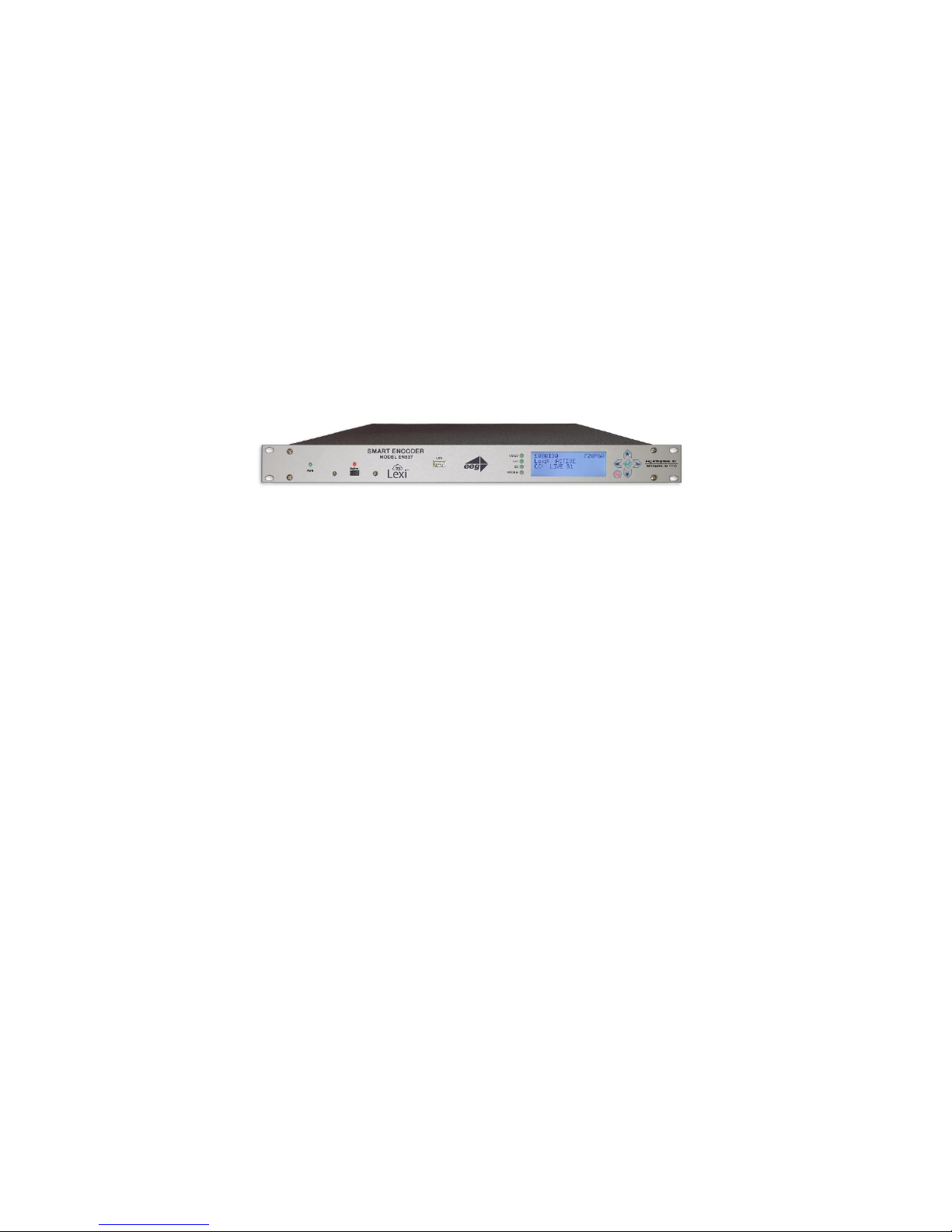
Front Panel .......................................................................................................................................................... 15
Rear Panel ........................................................................................................................................................... 16
GPIO Pinout / Wiring Detail ................................................................................................................................. 17
RS-232 / RS-422 Connection Detail ..................................................................................................................... 18
Encoder Specs ..................................................................................................................................................... 20
Developer Features ............................................................................................................................ 21
Encoder Command Concept ................................................................................................................................ 21
Startup Settings ................................................................................................................................................... 22
Command Reference ........................................................................................................................................... 23
Copyright 2018, EEG Enterprises, Inc. All rights reserved. The contents of this
manual may not be transmitted or reproduced in any form without the written
permission of EEG.
The revision date for this manual is June 12, 2018.
Copyright © 2018 EEG Enterprises, Inc 1
All Rights Reserved.
Page 4

EN537 Smart Encoder
Introduction
Product Description
The EN537 is an affordable caption encoder for broadcasters requiring basic caption insertion features.
The unit offers Automatic Captioning services through our cloud-hosted captioning service Lexi, supports
a direct serial port or TCP/IP connection, and can be also be equipped with an optional telco modem.
Please note the EN537 unit does not support using iCap to connect to captioners. However, an iCap
account is required for your EN537 to communicate with Lexi over a broadband connection.
List of Features
Connectivity to EEG’s Cloud-hosted Automatic Captioning service, Lexi.
Encoding of caption data sourced from previously encoded video sources, two RS232 serial ports,
or a dial-up modem (optional)
Encoding of CTA-708 standard closed captions from native 708 or legacy 608 (SD) sources
Caption relocation from configurable GPI triggers
Modules for web-streaming, scoreboard connectivity, and much more.
Local logging of caption input for future reference
Relay-bypassed master video and auxiliary video paths
Copyright © 2018 EEG Enterprises, Inc. 2
All Rights Reserved.
Page 5

EN537 Smart Encoder
Encoder Setup
Quick Network Setup
To use Lexi or access further features on the encoder’s web interface, you must first select Network
Settings from the front panel LCD menu and setup the encoder on your network.
Use a Static IP address on your network to assign the Encoder (recommended). It doesn’t
have to be, and in most cases should not be, a publically routable IP address.
Program a gateway address – the gateway address is typically the local network address of
your router. This is necessary if you plan to connect out of your local network to iCap or any
other application from the iCap Encoder.
Program a Subnet Mask for your network
Lexi only: Program your network to allow outbound connections to https://eegcloud.tv on
port 443. Your encoder must also have a valid DNS server configured under the Network tab
on the web portal. See additional Lexi setup instructions on Page 6.
As an alternative to these recommended steps you may also set up the encoder for DHCP – Selecting
DHCP will automatically pull available IP, gateway, and subnet information from your network.
IMPORTANT: With DHCP, your encoder’s assigned IP may change on its own which will affect how you
access the web interface for your encoder.
Video Input/Output
Put SDI video into the encoder. Output captions will appear on the SDI video output. Reference the
Rear Panel Diagram located in the Hardware Reference for a diagram of the rear-panel connector.
3 Copyright © 2018 EEG Enterprises, Inc.
All Rights Reserved.
Page 6

EN537 Smart Encoder
Test Captions
With video input connected to the encoder, you can send a stream of encoder-generated test captions
to the output video to ensure proper initial setup of the encoder. To send test captions navigate to
Utilities > Test Captions > Enable > On and a stream of test caption text should appear on the output of
your encoder. Note that video input is required to send test captions.
Setting Audio Levels
Your program audio source is typically embedded in the standard video input to your encoder. Audio
may also originate from a separate Analog or AES source (XLR connector input to encoder). To send this
program audio to captioners through iCap, you must first configure the audio settings through the front
panel menu of the encoder.
From the main menu go to Audio Setup > Audio Mix and set to Stereo or Surround appropriately. Next,
visit Audio Setup > Peak Level and ensure the audio level peaks at around 80% and does not warn
“Clipping!” This step is crucial for ensuring that quality audio is being sent to the captioner (quality audio
= quality captions).
If your audio levels are too low, or too high – you can achieve an appropriate level by adjusting the audio
source itself or simply adjusting the source audio level from the encoder front panel LCD menu Audio
Setup > Scale Audio which allows you to scale the audio up or down in 6 decibel increments.
Accessing Your Encoder’s Web Interface
Your Encoder’s web interface can be accessed through any computer on your local network and controls
many of your encoder’s applications, configurations, and features (see Security Settings and Password
Protection below for instructions on how to secure access to the web interface). You will see it
referenced many times throughout this manual.
The encoder must be connected on your network to access the web interface (reference Quick Network
Setup section on page 3). The web interface is accessed by entering the IP address assigned to your
encoder in your computer’s web browser. If you set the encoder up with a static IP address, the address
for your web interface will be the same. If you set the encoder up with DHCP, the address can change at
will and you should check the IP from the front panel of your encoder at System Setup > Network > IP
Address to ensure you are using the correct IP to access the web interface.
Copyright © 2018 EEG Enterprises, Inc. 4
All Rights Reserved.
Page 7

EN537 Smart Encoder
Security Settings and Password Protection
To limit access to the encoder’s web interface for security purposes, you may set up a password through
the front panel of your encoder via Setup > Security > Security Mode > Password. This password will be
for access to the encoder’s web interface, not the encoder LCD menu. Many of the encoder’s crucial
features are controlled via the encoder’s web interface.
Setting Date & Time
The Date and Time can be set by selecting Date/Time from the side menu on the web interface.
Figure 1: Date/Time Settings on the Encoder Web Interface
Updating Your Encoder
Before updating you must first download the latest update file for your encoder model from the product
updates section of our website https://eegent.com/support/product_updates
Once you have downloaded the latest version for your encoder model you can apply it to the encoder
either through the web interface OR the front panel USB port / LCD Menu.
Web Interface: Select Update from the left side menu. Browse for the update file
downloaded from our website, then click Upload, and finally click Proceed.
USB / LCD: Transfer the update file to any USB stick. Insert the memory stick into the front
panel USB port, navigate to the System Setup > Update from the LCD menu, and press enter
to proceed and install the update. A message will appear on the LCD screen when the update
has finished. Do not remove the memory device while the update is running.
Some updates will require a power-cycle before they take effect; in this case, the encoder will power
down automatically once the update is complete.
5 Copyright © 2018 EEG Enterprises, Inc.
All Rights Reserved.
Page 8
EN537 Smart Encoder
Lexi Setup and Testing
If you did not indicate interest in Lexi at the purchase of your encoder, please contact EEG technical support
at 516-293-7472 to obtain the necessary iCap and Lexi / EEG Cloud credentials. Also, be sure your EN537 is
properly setup on your network prior to setting up Lexi (instructions on Page 3).
Please note the EN537 unit does not support use of iCap to connect to captioners. However, an iCap account
IS required for your EN537 to communicate with Lexi over a standard broadband connection.
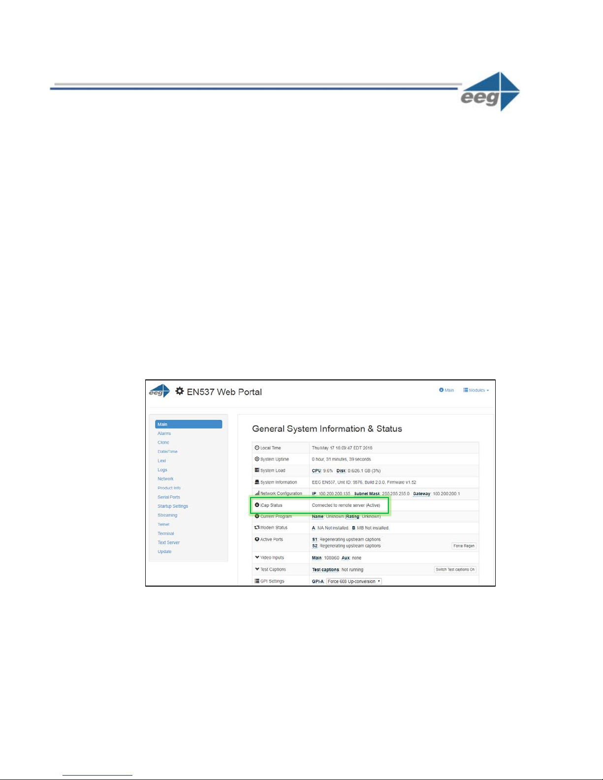
1. Confirm iCap Connectivity and Know Your iCap Access Code:
From the main page of EN537 web interface, confirm the iCap Status says Connected to
remote server. If inactive, contact EEG support for credentials.
Your iCap Access Code can be found in the shipping documentation provided with your
Encoder. This will be used in the next step to enable Lexi to access live program audio from,
and return automatic captions to, your encoder over iCap.
Figure 2: Active iCap Status on Encoder’s Web Interface Main Page
Copyright © 2018 EEG Enterprises, Inc. 6
All Rights Reserved.
Page 9

EN537 Smart Encoder
Language
The base language models supported by Lexi currently include English-US,
English-UK, and Spanish.
Custom Model
Through the EEG Cloud web site, you can manage your Lexi account and create
custom language models to further improve accuracy for your unique
application. This dropdown box will display all of the custom models available
under your active EEG Cloud account.
2. Configure Lexi on Your Encoder
Select the Lexi module from the left hand menu of the web interface. Enter your EEG Cloud
Username and Password along with your encoder’s Access Code. If this information has not
been preconfigured prior to shipment, noted in the paperwork that came with your encoder,
or provided to you via e-mail by EEG Support contact us at 516-293-7472 to setup your Lexi
account and obtain this information.
Ensure additional preferences are configured as desired. Below are descriptions for each
setting field. Once this is complete you may click Apply Settings.
Figure 3: Lexi Module on Encoder’s Web Interface Main Page
Speech Recognition
7 Copyright © 2018 EEG Enterprises, Inc.
All Rights Reserved.
Page 10

EN537 Smart Encoder
Caption Service
Choose from primary language (CC1/S1) and secondary language (CC3/S2)
options.
Number of Rows
The number of rows per roll-up caption can range from 2 to 4.
Vertical Position
CTA-608 base row options range from 2 (top of the screen) to 15 (bottom of
the screen).
Horizontal Position
Choose a left horizontal offset from 0 to 28 characters.
Capital Letters
When enabled, all captions will be written in upper-case.
Enable Module
Lexi must be enabled in order for the encoder to communicate with Lexi and
receive captions from the cloud.
Activation Mode
When "Always active" is selected, a Lexi captioning job will be started
immediately upon enabling the client m
selected, a Lexi captioning job will start when GPI 5 is
until GPI-E is de-asserted.
Inactivity Timeout
A Lexi job that that runs for this amount of time without any dialog being
transcribed will be terminated automatical
you want jobs to be able to run indefinitely without dialog.
Block Lexi on
Setting this to "Yes" will ensure that Lexi will not generate captions when
upstream data is present. The time in parentheses indicates how long
upstream captions will have to be absent in order for Lexi to start up again.
Monitor Service
With GPO 2
When selected, GPO 2 will be active when Lexi is captioning to the selected
access code, and will be inactive otherwise.
Caption Display
Lexi Client
Upstream Captions
odule. When "Require GPI-E" is
asserted and will run
ly by the server. Set to "None" if
Copyright © 2018 EEG Enterprises, Inc. 8
All Rights Reserved.
Page 11

EN537 Smart Encoder
Other Live Captioning Methods
Modem (Optional Add-on)
Standard RJ-11 connection. Connect to a phone line to enable dial-up captioning and provide your captioner
with the telephone number associated. Using a PBX or other digital non-POTS system is NOT recommended
- many of these are not compatible with modem communications. Once connected, the LED on the front
panel of your encoder labeled “MDM” will turn green.
Telnet
Enable telnet via the encoder’s web interface and select a port. Configure your firewall to allow a captioner
to get to your encoder on the designated port and then give your caption service provider the port number
and public IP address.
RS-232 / RS-422 (Teleprompters or Other Devices)
See hardware section for cabling detail. Serial port settings are controlled through the web interface of the
encoder by selecting Serial Ports from the left side menu or by navigating to System Setup > P1 Mode from
the front panel LCD menu of the encoder. The EN537 supports RS-232, RS-422, and RS-422 Sony (with RS422 and RS-422 Sony options configurable on Port 1 only). Default settings are 1200 baud, odd parity, and
7 data bits. Customized settings are sticky after power cycles. Modem will automatically take priority when
active so that the prompter can be overridden as desired.
Figure 4: Serial Port Settings in the Web Interface
9 Copyright © 2018 EEG Enterprises, Inc.
All Rights Reserved.
Page 12

EN537 Smart Encoder
Common Applications
SDI Caption Bridging
Caption bridging copies captions from the source video (AUX) to the master video output. This happens
automatically when you have a captioned video input connected to the AUX connector.
Dual Encoding (Two Video Paths)
The EN537 can caption to two independent video channels, embedding the same closed captions in both
channels. Any two supported video standards can be combined on the inputs to produced closed-captioned
video on the respective outputs. For example, if 1080i60 HD-SDI is present on the Master input and NTSC
SD-SDI is present on the AUX input, the Master output will be closed-captioned 1080i60 HD-SDI and the
AUX output will be closed-captioned NTSC SD-SDI.
GPI Relocation
GPI Relocation allows on-command placement control of closed captions on your output to avoid blocking
essential action such as screen crawls and emergency information. You can control this feature by accessing
the Main section of the side menu of the encoder web interface and scrolling down to the GPI settings at
the bottom.
The screen is mapped into 15 regions from top to bottom that can be protected with the use of GPI settings.
If you are creating a GPI switch and require a diagram of the GPIO Pinout – see the GPIO pinout / wiring
detail found in the Hardware Reference section of the manual
Figure 5: GPI Settings Found in “Main” Section of the Encoder Web Interface
Copyright © 2018 EEG Enterprises, Inc. 10
All Rights Reserved.
Page 13

EN537 Smart Encoder
Caption Uplink to Web Streaming Media Servers (Streaming Add-On)
The Streaming feature posts real-time caption data to external web services for delivering high-quality webbased closed captioning.
To determine if Streaming is installed on your unit, access your encoder’s web interface, look for an entry
that says Streaming on the left side menu and select it. If you are prompted for a license key, the feature is
not installed and can be purchased by contacting the EEG sales team.
While the HTTP Streaming Uplink module is active, all closed captions through the encoder will be passed
to the streaming server. These captions may be locally inserted to the video through iCap, telnet, or dial-up
mechanisms (encoders only), or they may be present on the input video, and originally coded using either
real-time/roll-up or offline/pop-on workflows.
Before using the Streaming feature, you will need a stream URL for posting captioning data (example:
http://in.videolinq.net/caption), a stream ID or username, and a password.
Further instruction for this feature may be found at https://eegent.com/support/resources
Figure 6: Streaming Settings on the Encoder Web Interface
11 Copyright © 2018 EEG Enterprises, Inc.
All Rights Reserved.
Page 14
EN537 Smart Encoder
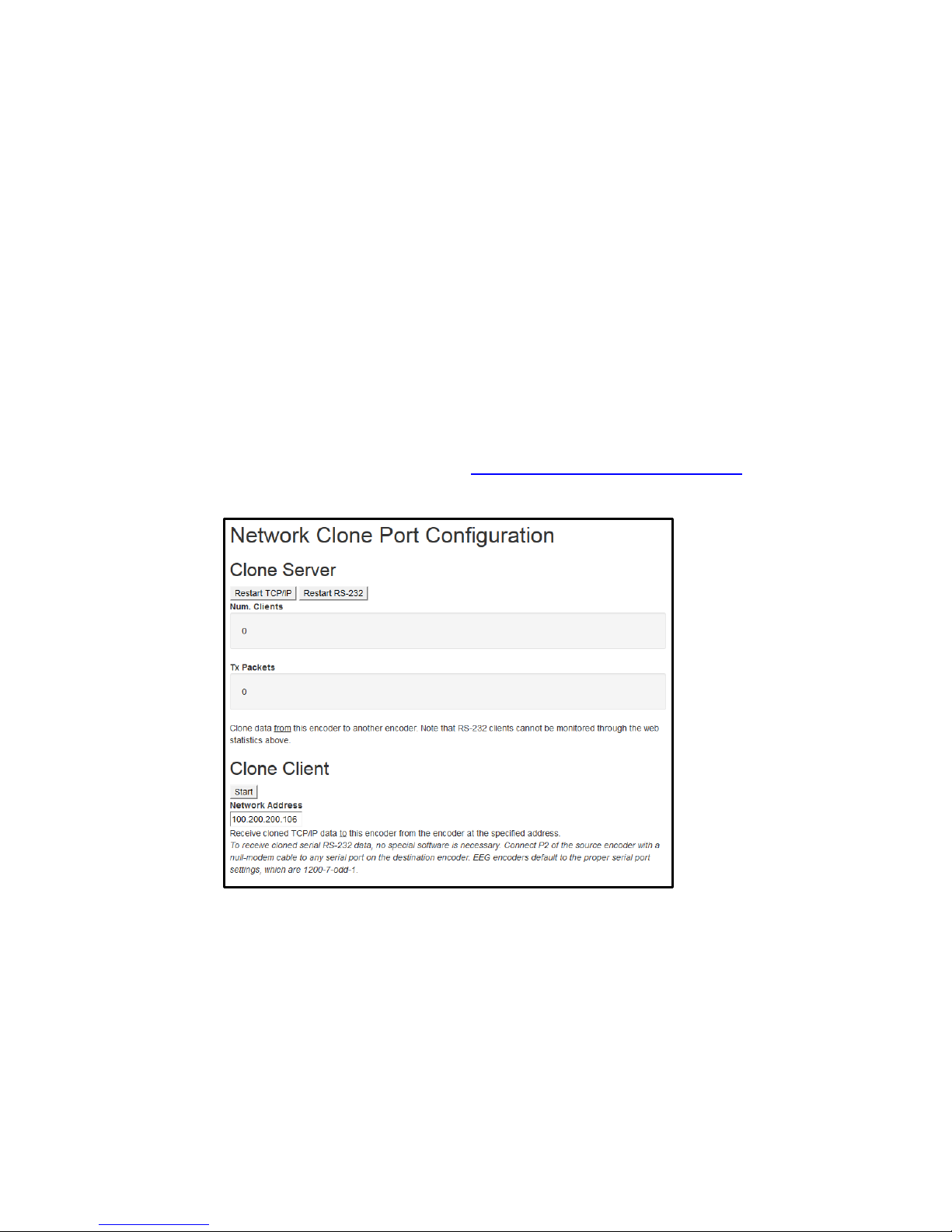
Cloning Live Data to Additional Encoders (Clone Add-On)
The Clone feature re-transmits all control commands and caption data to one or more additional caption
encoders. The additional encoders can be connected either through RS-232, or through the Clone TCP/IP
interface.
To determine if Clone is installed on your unit, access your encoder’s web interface, look for an entry that
says Clone on the left side menu and select it. If you are prompted for a license key, the feature is not
installed and can be purchased by contacting the EEG sales team.
The master encoder must have the Clone port optional software installed, and then set up through clone
section of the web interface. When any “Clone Server” option is enabled, the encoder will copy commands
and data that are received through the dial up modem (MA), iCap, telnet, or RS-232 (P1, plus P2 if it is being
used for input and not Clone output). You can also choose to copy these commands to the RS-232 port
(Start RS-232).
Further documentation for this feature may be found at https://eegent.com/support/resources
Figure 7: Clone Settings on the Encoder Web Interface
Copyright © 2018 EEG Enterprises, Inc. 12
All Rights Reserved.
Page 15

EN537 Smart Encoder
XDS Insertion
Extended Data Services (XDS) is an NTSC Field 2 data channel that provides information to viewers about the
program that is being aired. XDS is used to transmit FCC-mandated program ratings to allow viewer V-chip
filtering. XDS is a part of the CTA-608 standard for SD broadcasts, and should be included in the 608
compatibility bytes of CTA-708 compliant HD broadcasts. XDS insertion is typically controlled through a serial
connection to an automation server and is compatible with Imagine/Harris, Snell, and EEG’s XDS Xpress
solution.
XDS data packets can be loaded into the Encoder’s queue with one simple command, and be held for any
specified time period. Each individual packet type can be independently set for upstream or local priority,
and permanent packets can be stored in Non-Volatile Memory and inserted automatically whenever the
Encoder is operating. A List of XDS commands may be found in the Command Reference section of this
manual.
13 Copyright © 2018 EEG Enterprises, Inc.
All Rights Reserved.
Page 16

EN537 Smart Encoder
Additional Features
Caption Absence Alarm
The Caption Absence Alarm feature, accessed from the Alarm section of the side menu of the encoder web
interface, allows you to set alarms to automatically alert you when caption presence is not detected on the
encoder for a certain amount of time. This is a useful feature for monitoring caption activity on your encoder.
Figure 8: GPI Alarm Settings on the Encoder Web Interface
Caption Input Blocking
You can block caption input to your encoder via the following non-relocation GPI functions found in the
GPI Settings on your web interface. They are as follows:
Modem Lockout: Blocks caption input from the Modem
P2 Lockout: Blocks caption input from Serial Port 2
Force Regen: Blocks caption input from Modem, P2, and iCap
Capturing Incoming VANC or 608 Data for Analysis
You can capture and save VANC data from the master video input to a USB stick for review or
troubleshooting. Place a USB stick into the USB port on the front panel of your encoder and navigate to
Utilites > Capture All VANC from the front panel LCD. Press ENTER to begin downloading the VANC data or
CANCEL to exit. To stop capturing VANC data press any front panel key. Depending on the size/type of
memory device used, there may be a momentary delay before the device is detected. If you see “Failed:
Insert USB Disk”, wait a few seconds and try again. For questions about analyzing your VANC data. Please
contact our support team at 516-293-7472 or support@eegent.com
Copyright © 2018 EEG Enterprises, Inc. 14
All Rights Reserved.
Page 17

EN537 Smart Encoder
LCD Display
Control Pad
Active On /
Bypass
USB Port
Powe r On
LED
Stat us Ind icator LEDs:
• Video Input
• Lex i Co nn ect iv it y Status
• Caption Presence
• Modem Connection
Power Switch
There is one power switch on the rear panel for each power cable connected
to the unit.
Power On LED
There is one power LED for each power supply connection provided with the
unit
Active
Toggles the Encoder between active operations and Relay Bypass mode. In
Relay Bypass mode, the signal at the master video input is routed directly
through to the master video output, while the signal at the auxiliary video
input is routed directly through to the auxiliary vi
is inactive.
Active On LED
The Active On LED will light green when the unit is in active operating mode.
The LED will turn off when the Encoder is in Relay Bypass mode.
LCD Screen
The LCD Screen provides access to the unit’s front panel configuration menu.
Status information is displayed when the menu is not in use. Press the “check
mark” button to enter the menu at any time.
Control Pad
The Control Pad provides menu navigation for the front panel configuration
menus. The control pad buttons are:
(marked by an ‘X’), LEFT, RIGHT, UP, and DOWN.
Hardware Reference
Front Panel
15 Copyright © 2018 EEG Enterprises, Inc.
All Rights Reserved.
deo output. Video output 2
ENTER (marked by a check), CANCEL
Page 18

EN537 Smart Encoder
USB Port
The front panel USB port provides firmware upgrade capability via a flash
memory device. Updates can be applied through the USB port as well as the
web interface. See
more.
Optional
Power 2
Ethernet
Por t (L AN)
GPIO
Master
Video I n
Out 1 Out 2 AUX In
Modem
RS232
Por t (P2)
RS232/422
Por t (P1)
Optional
Audio Input
AUX Ou t
Pri ma ry
Power 1
Primary Power 1
AC power input, 120 – 240 V, 50-60 Hz tolerant. Connects to the unit’s AC
power source. Corresponding switch powers unit on or off.
Optional Power 2
AC power input, 120 – 240 V, 50-60 Hz tolerant. Connects to the unit’s AC
power source (second power supply does not come standard).
GPI In & Out
Two blocks of 8 GPI input switches and 8 GPO output notifications. Switch
functions vary based on software configurations.
Ethernet Port
Used to connect the encoder to your local network for access to the web
interface and Lexi.
static or DHCP IP address set in the front panel configuration menu.
Master Video In
Input for program video source - can use 3G-SDI, HD-SDI, or SD-SDI
Out 1
Relay-bypass protected primary video output.
Out 2
Non relay-bypass protected copy of the primary video output signal.
Rear Panel
Updating Your iCap Encoder section on page 5 to learn
The encoder will be reachable on your network using the
Copyright © 2018 EEG Enterprises, Inc. 16
All Rights Reserved.
Page 19

EN537 Smart Encoder
15
13
11 9 7 5 3 1 16
14
12
10 8 6 4 2
Pin(s)
Input
1,3,5,7,9,11,13,15
Ground
2
GPI-A
4
GPI-B
6
GPI-C
8
GPI-D
10
GPI-E
12
GPI-F
14
GPI-G
16
GPI-H
Pins
Output
15, 16
1
13, 14
2
11, 12
3
9, 10
4
7, 8 5 5, 6 6 3, 4 7 1, 2
8
GPIO Pinout / Wiring Detail
The GPIO pins are located on the two 16-pin connectors on the rear panel of the unit. The top connector is
used for the GPI switches and the bottom is used for the GPO switches, with the pins numbered in the
following manner on each connector:
GPI Pin Assignments
The GPIs use the upper 16-pin connector, which mates to a female IDC-16 connector. The pin
assignments are given in the table below:
GPO Pin Assignments
The GPIs use the upper 16-pin connector, which mates to a female IDC-16 connector. The pin
assignments are given in the table below:
17 Copyright © 2018 EEG Enterprises, Inc.
All Rights Reserved.
Page 20

EN537 Smart Encoder
RS-232 Protocol
Pin
Master
EN537 1
2
Rx
Tx
3
Tx
Rx
4
5
Ground
Ground
6-9
RS-422
Pin
Master
EN537
1
Rx-
Tx-
2
Rx+
Tx+ 3 Tx+
Rx+
4
Tx-
Rx-
5
Ground
Ground
6-9
RS-422 Sony
Pin
Master
EN537 1
2 Rx-
Tx- 3 Tx+
Rx+
4
5
Ground
Ground
6 7 Rx+
Tx+ 8 Tx-
Rx- 9
RS-232 / RS-422 Connection Detail
Both Serial ports 1 and 2 use DB-9 connectors. Only serial port 1 supports RS-422 and RS-422 Sony. See the
following PIN assignments:
Copyright © 2018 EEG Enterprises, Inc. 18
All Rights Reserved.
Page 21

EN537 Smart Encoder
DB-9 Female connector pinout on rear of EN537 encoder:
These ports can be connected directly to a standard PC serial port with a 9-pin, three wire straight serial
cable. A “null modem” cable MAY NOT be used for this purpose since it will reverse the connections of pins
2 and 3. Null Modem cable may be used only when the intent is to connect two encoders together via the
serial port (see Cloning on page 17).
19 Copyright © 2018 EEG Enterprises, Inc.
All Rights Reserved.
Page 22

EN537 Smart Encoder
Encoder Specs
HD-SDI Video Inputs
Number of Inputs ............................... 2
Connector ........................................... BNC per IEC 169-8
Format ............................................... 3G (SMPTE 424M), HD (SMPTE 292M), and SD (SMPTE 259M and 344M)
Input Level .......................................... 800 mV p-p ± 10%
Input Impedance ................................ 75 Ohms
Equalization ........................................ Automatic up to 100m @ 3 Gb/s with Belden 1694 or equivalent
HD-SDI Video Outputs
Number of Outputs ............................ 3
Output 1 ............................................. Master (relay bypass protected)
Output 2 ............................................. Master copy
Decoder Out ....................................... Auxiliary (relay bypass protected)
Connector ........................................... BNC per IEC 169-8
Output Level ....................................... 800 mV p-p ± 10%
Output Impedance ............................. 75 Ohms
DC Offset ............................................ 0V ± 0.5V
Rise/Fall Time ..................................... 200 pS nominal
Overshoot ........................................... < 10% of amplitude
Wide Band Jitter ................................. < 0.2 UI
DATA PORTS
LAN ..................................................... RJ45 connector, 10/100/1000 Base T TCP/IP
USB ..................................................... Three standard USB ports, one on front panel and two on rear
Serial Ports ....................................... Two serial DB-9 jacks, Selectable RS-232C / RS-422.
Serial Data Input Format ................... 7 data bits, odd parity, 1 stop bit, settable between 1200-38400 baud
Modem .............................................. Paid Option. One RJ-11 telephone jacks 1200/2400 baud
GPI/GPO ............................................. Two ports which each mate to female IDC-16 connectors, Switches rated
AUDIO PORTS
Port 1 .................................................. LTC time code input
Port 2 .................................................. Program audio input for streaming audio applications
Connector ........................................... Female XLR
Format ................................................ Balanced analog or AES balanced 110-ohm digital
FRONT PANEL
Display ................................................ Back-lit LCD display with six-button keypad and navigable menus for unit
Power ................................................. Unit power switch with LED indicator
Active On ............................................ Encoder bypass switch with LED indicator
PHYSICAL
Dimensions ......................................... 19” rack mount x 1 RU x 16.5” deep
ELECTRICAL
Power Supply ..................................... 115/230V AC 50/60Hz
Power Consumption………………………… Inrush: 118VA 36W Normal: 40VA 36W .31 Amps .91 Power Factor
to 1A / 30 VDC
configuration
Copyright © 2018 EEG Enterprises, Inc. 20
All Rights Reserved.
Page 23

EN537 Smart Encoder
Developer Features
Encoder Command Concept
Encoder Commands allow you to communicate with and control the operation of your encoder either
manually or through your custom written software that contains any combination of the commands detailed
in this section. All commands begin with a leading control code of <CTRL+A> or the ASCII hex code 01 for
developers writing software. All commands must end with a carriage return (the <ENTER> key on a keyboard
or 0D in ASCII hex). For manual entry of commands, the three following methods may be used. A Full
Command Reference may be found at the end of this section.
Telnet: Commands may be entered through a telnet connection to your encoder only after you’ve enabled
a telnet connection through your encoders web interface (select Telnet from the side menu)
Web Terminal: The Command Terminal is found on the web interface of your encoder (select Terminal from
the side menu). This emulates the serial port interface to your encoder and allows you to enter commands
directly from your encoders web interface (see figure 19).
RS-232: Commands may be entered through an RS-232 connection to your encoder. Default settings on the
encoder allow entry through RS-232 right out of the box.
Figure 9: Command Terminal on the Encoder Web Interface
21 Copyright © 2018 EEG Enterprises, Inc.
All Rights Reserved.
Page 24

EN537 Smart Encoder
Startup Settings
The Startup Settings Editor enables entry of Encoder commands that will run every time the encoder starts
up. Use Startup Settings whenever you want a setting to be “sticky”; settings entered through the Web
Terminal or the serial port only are not sticky and will revert to defaults when the encoder is power-cycled.
Startup Settings can be accessed via the encoder web interface by selecting Startup Settings from the side
menu.
To use the Startup Settings editor, type any Smart Encoder command into the command box. Omit the
<CTRL+A> character entirely as this character is implied at the beginning of each line. To add additional
commands, press the ‘+’ button and more lines will appear.
When you have entered commands for all the settings that you want to make sticky, click Update Startup
Settings. The configuration changes will take the next time the encoder starts up.
Figure 10: Startup Settings on the Encoder Web Interface
Copyright © 2018 EEG Enterprises, Inc. 22
All Rights Reserved.
Page 25

EN537 Smart Encoder
Command Reference
Local Entry Modes
Regeneration Mode:
Regenerate Upstream VANC <CTRL+A>! [ON/OFF] <ENTER>
Ignore Upstream Caption Channel <CTRL+A>6 Channel <ENTER>
Return Upstream Caption Channel <CTRL+A>7 Channel <ENTER>
Begin PassThru Mode <CTRL+A>3 [Pairing] [Field] <ENTER>
End PassThru Mode <CTRL+C>
Begin RealTime Mode <CTRL+A>2 [Channel] [Rollup] [bBase] <ENTER>
End RealTime Mode <CTRL+C>
HD Output Types
HD VANC Insertion:
VANC Insertion Disabled <CTRL+A># OFF <ENTER>
VANC Insertion Enabled <CTRL+A># ON <ENTER>
VANC Line Change <CTRL+A>f 334 [Line] <ENTER>
VANC No 333 Detection <CTRL+A>f vanc [Line] <ENTER>
333 Serial Output:
333 Output Manual configure <CTRL+A>f 333 <ENTER>.
GA Serial Output:
GA Serial Output <CTRL+A>f ga <ENTER>.
XDS Insertion
XDS Entry:
Enable XDS Entry <CTRL+A>O XDS O <ENTER>
Load XDS Packet <CTRL+A>P Packet Duration Content [Priority]
<ENTER>
Sample XDS entries <CTRL+A>P 103 –1 {Evening News} <ENTER>
<CTRL+A>P 105 00.30.00 4844 <ENTER>
XDS Packet:
Load Default XDS Packet <CTRL+A>P LPacket Duration Content [Holdoff]
<ENTER>
Sample XDS entries <CTRL+A>P L105 –1 4840 <ENTER>
Load NVM XDS packet <CTRL+A>w <CTRL+A>P Packet -1 Content <ENTER>
23 Copyright © 2018 EEG Enterprises, Inc.
All Rights Reserved.
Page 26

EN537 Smart Encoder
Report XDS Queue <CTRL+A>e [Packet] <ENTER>
Delete XDS Packet <CTRL+A>P Packet <ENTER>
Block Upstream XDS <CTRL+A>T -Class00 <ENTER>
End Blocking <CTRL+A>T Class00 <ENTER>
End Blocking Example <CTRL+A>T –0100 <ENTER>
URL Encoding
Message Input:
Begin Message Input <CTRL+A>0 Title [Channel] [Repeat] [K/D] [O/H]
[N/L] <ENTER>
End Message Input <CTRL+C>
Transmission Delay <CTRL+B> Delay (delay in seconds)
Message Input Example <CTRL+A>0 EEG_URL T2 3 D O N <ENTER>
EEG on the Web <ENTER>
<http://www.eeg.tv>[t:p][C510]<ENTER> <CTRL+C>
Output Message <CTRL+A>1 Title [Channel] [Repeat] [K/D] [O/H]
[N/L] <ENTER>
Remove Message from Queue <CTRL+A>4 Title [K/D] <ENTER>
Display Message Status <CTRL+A>9 [Channel] <ENTER>
Begin Set Output Queue <CTRL+A>8 [Channel] <ENTER>
End Set Output Queue <CTRL+C>
Display Output Queue <CTRL+A>B <ENTER>
Encoder Status Commands
Status Commands:
Report Identification <CTRL+A>? <ENTER>
Report Port Activity <CTRL+A>O <ENTER>
Modem Status <CTRL+A>+ [Modem] <ENTER>
Recovery Status <CTRL+A>A <ENTER>
SD Video Presence <CTRL+A>b <ENTER>
Report Switch Setting <CTRL+A>S <ENTER>
Monitor Line 21 <CTRL+A>5 [Channel] [I/O] <ENTER>
End Monitoring <CTRL+C>
Copyright © 2018 EEG Enterprises, Inc. 24
All Rights Reserved.
 Loading...