

Page 1
EEG DE285 HD Caption
Decoder/VANC Monitor
Product Manual
EEG Enterprises, Inc.
586 Main Street
Farmingdale, New York 11735
TEL: (516) 293-7472 FAX: (516) 293-7417
Copyright © EEG Enterprises, Inc. 2009-2011
All rights reserved.
Page 2

DE285 HD Caption Decoder/VANC Monitor
Contents
1. Introduction . . . . . . . . . . . . . . . . . . . . . . . . . . . . . . 3
1.1. Product Description . . . . . . . . . . . . . . . . . . . . . . . 3
2. Installation . . . . . . . . . . . . . . . . . . . . . . . . . . . . . . 4
2.1. Front Panel . . . . . . . . . . . . . . . . . . . . . . . . . . . . 4
2.2. Rear Panel . . . . . . . . . . . . . . . . . . . . . . . . . . . . . 6
3. Front Panel Menus . . . . . . . . . . . . . . . . . . . . . . . . . . 7
3.1. Decoder Setup . . . . . . . . . . . . . . . . . . . . . . . . . . . 8
3.2. System Setup . . . . . . . . . . . . . . . . . . . . . . . . . . . 10
3.3. Utilities . . . . . . . . . . . . . . . . . . . . . . . . . . . . . . . 12
4. OSD . . . . . . . . . . . . . . . . . . . . . . . . . . . . . . . . . . . 14
4.1. XDS Monitor . . . . . . . . . . . . . . . . . . . . . . . . . . . . 14
4.2. AFD Monitor . . . . . . . . . . . . . . . . . . . . . . . . . . . . 15
4.3. Caption Service Monitor . . . . . . . . . . . . . . . . . . . . . 15
4.4. Audio Metadata Monitor . . . . . . . . . . . . . . . . . . . . . 15
4.5. Audio Monitor . . . . . . . . . . . . . . . . . . . . . . . . . . . 15
4.6. Error Monitor . . . . . . . . . . . . . . . . . . . . . . . . . . . 16
5. Web Tools Suite . . . . . . . . . . . . . . . . . . . . . . . . . . . . 17
5.1. Packet Display Module . . . . . . . . . . . . . . . . . . . . . . 18
5.2. Data Decoder Module . . . . . . . . . . . . . . . . . . . . . . 19
5.2.1. AFD Decoder . . . . . . . . . . . . . . . . . . . . . . . . 19
5.2.2. XDS Decoder . . . . . . . . . . . . . . . . . . . . . . . . 20
5.2.3. SCTE104 Decoder . . . . . . . . . . . . . . . . . . . . . 21
5.3. Caption Decoder Module . . . . . . . . . . . . . . . . . . . . . 21
5.4. ANC Trigger . . . . . . . . . . . . . . . . . . . . . . . . . . . . 22
5.5. VANC Capture . . . . . . . . . . . . . . . . . . . . . . . . . . . 25
5.6. Logging . . . . . . . . . . . . . . . . . . . . . . . . . . . . . . 26
5.6.1. Log Viewer . . . . . . . . . . . . . . . . . . . . . . . . . 27
5.6.2. Logging/OSD Alarm Settings . . . . . . . . . . . . . . . 28
5.7. OSD . . . . . . . . . . . . . . . . . . . . . . . . . . . . . . . . . 34
5.7.1. Screen Configuration . . . . . . . . . . . . . . . . . . . 34
5.7.2. Alarm/Error Configuration . . . . . . . . . . . . . . . . 36
5.7.3. Audio Monitor Configuration . . . . . . . . . . . . . . . 36
5.8. Settings . . . . . . . . . . . . . . . . . . . . . . . . . . . . . . 36
Copyright ©2009-2011 EEG Enterprises, Inc.
All rights reserved.
1
Page 3

DE285 HD Caption Decoder/VANC Monitor
5.8.1. Upgrade . . . . . . . . . . . . . . . . . . . . . . . . . . 36
5.8.2. System Settings . . . . . . . . . . . . . . . . . . . . . . 37
5.8.3. Alarm Settings . . . . . . . . . . . . . . . . . . . . . . . 38
5.8.4. VANC Settings . . . . . . . . . . . . . . . . . . . . . . . 38
5.8.5. Log Settings . . . . . . . . . . . . . . . . . . . . . . . . 38
5.8.6. SNMP Settings . . . . . . . . . . . . . . . . . . . . . . . 39
5.8.7. Remote Settings . . . . . . . . . . . . . . . . . . . . . . 39
Appendices . . . . . . . . . . . . . . . . . . . . . . . . . . . . . . . . 40
Appendix A GPI/GPO . . . . . . . . . . . . . . . . . . . . . . . . . . 40
A1. GPI . . . . . . . . . . . . . . . . . . . . . . . . . . . . . . . . . 40
A1.1. Layout Scrolling . . . . . . . . . . . . . . . . . . . . . . 40
A2. GPO . . . . . . . . . . . . . . . . . . . . . . . . . . . . . . . . . 41
A2.1. Caption Presence Alarm . . . . . . . . . . . . . . . . . 41
Appendix B SNMP Traps . . . . . . . . . . . . . . . . . . . . . . . 41
Appendix C Video/Connector Specifications . . . . . . . . . . . 42
Appendix D Binary ANC Dump Data Format . . . . . . . . . . . 43
Copyright 2009-2011, EEG Enterprises, Inc. All rights reserved.
The contents of this manual may not be transmitted or reproduced
in any form without the written permission of EEG.
The revision date for this manual is September 20, 2011.
2 Copyright ©2009-2011 EEG Enterprises, Inc.
All rights reserved.
Page 4

DE285 HD Caption Decoder/VANC Monitor
1. Introduction
1.1. Product Description
The DE285 HD Caption Decoder/VANC Monitor is an all purpose closed
caption decoder which creates an HD open caption display for monitoring CEA–708 data quality and full standards compliance, while also
providing an extensive VANC monitoring suite. The DE285 can be configured from the front panel to display caption data in HD Services 1
through 6, and all caption channels present in the EIA-608 compatibility
bytes. In addition to producing broadcast quality open–captioned video,
the DE285 decodes a wide array of metadata types, including AFD (Active Format Descriptors), audio metadata and XDS. The DE285 also features HANC embedded AES audio decoding with channel levels, peaks,
and phase detection.
The DE285 comes equipped with a powerful Web-based VANC Analysis
Tool for viewing and capturing live VANC data, sorted by service type,
DID/SDID or line number. The DE285 Web Tools offer an efficient new
way to monitor VANC packets, providing programmable triggers with
logging for packet drop-outs or changes, as well as other features.
The EEG DE285 offers a comprehensive VANC monitoring solution and
HD closed caption decoder with the proven quality and full standards
compliance of the industry’s leading provider of HD closed caption decoding equipment.
Copyright ©2009-2011 EEG Enterprises, Inc.
All rights reserved.
3
Page 5

DE285 HD Caption Decoder/VANC Monitor
2. Installation
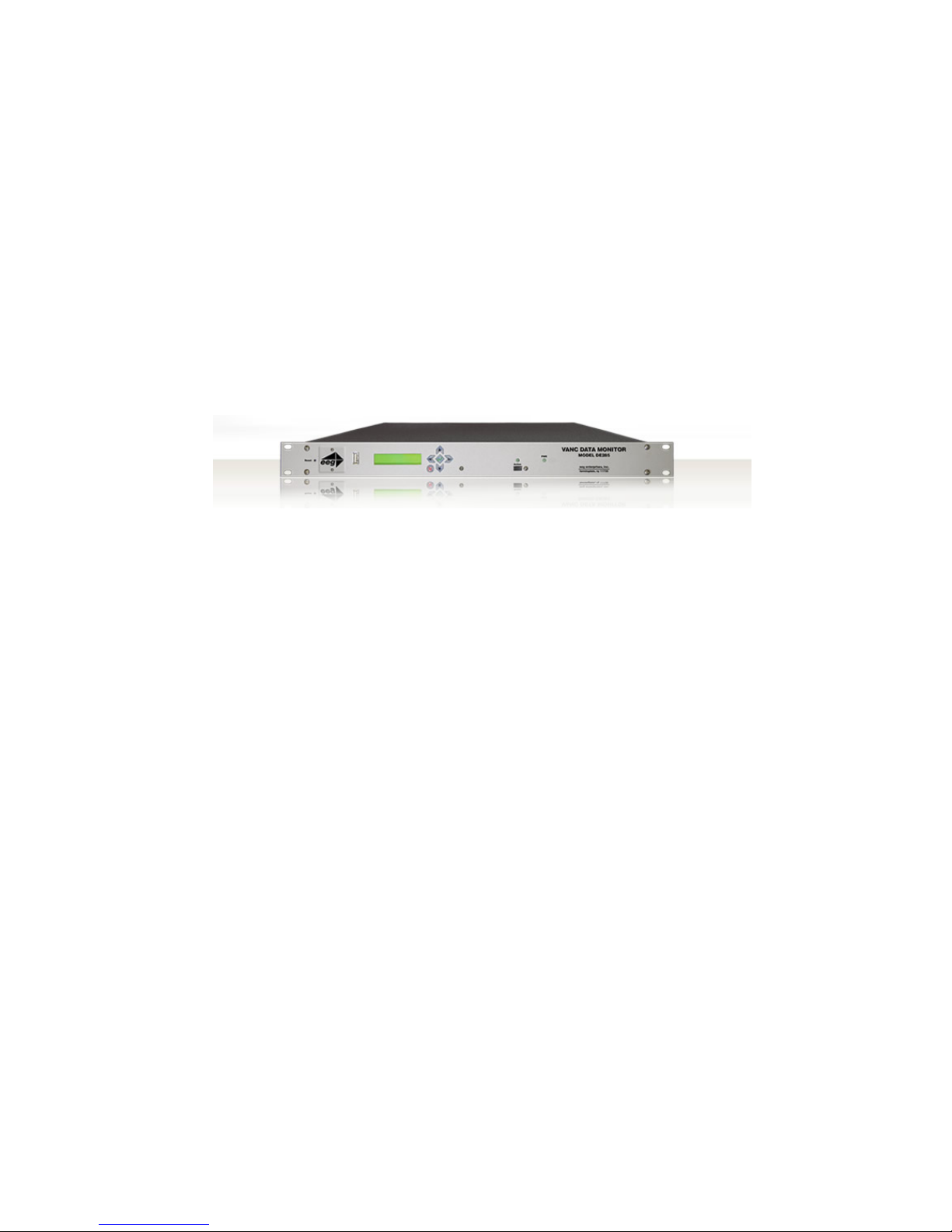
2.1. Front Panel
The DE285 front panel is shown below, followed by a brief guide to its
functions.
Power On LED
The Power On LED will light steady green when
the unit is powered on.
Active Button
Toggles the Decoder between active operation
(LED on) and Relay Bypass mode (LED off). In
Relay Bypass mode, the signal at the Program
video input is routed directly through to the Program video output, with no on-screen display created. All other inputs and outputs are inactive
and the web analysis tools cannot be used.
Control Pad
The Control Pad navigates menus and changes
settings in the front panel configuration menus.
The control pad buttons are: ENTER (marked
by a check), CANCEL (marked by an X), LEFT,
RIGHT, UP and DOWN. In most configuration
menus, use LEFT and RIGHT to navigate between parameters, UP and DOWN to change the
value of the selected parameter, ENTER to select a category or save a change, and CANCEL
to return to the previous menu without saving
changes. See Front Panel LCD Menu in Decoder
Operation for further details.
USB Port
A front panel USB port is provided to enable
quick and easy software upgrade.
4 Copyright ©2009-2011 EEG Enterprises, Inc.
All rights reserved.
Page 6

DE285 HD Caption Decoder/VANC Monitor
LCD Screen
The LCD Screen will provide access to the unit’s
front panel configuration menu. When the menu
is not in use, video status is shown. See the next
section for front panel configuration options.
Copyright ©2009-2011 EEG Enterprises, Inc.
All rights reserved.
5
Page 7

DE285 HD Caption Decoder/VANC Monitor
2.2. Rear Panel
The DE285 rear panel is shown below, followed by a guide to the connectors located there.
Power
AC power input, 120–240 V, 50–60 Hz tolerant.
Connect to the unit’s primary power source. Turn
on/off with switch next to connector.
Program In
Video input for the Program video chain. The onscreen display will be burned onto this video signal.
Program Out 1
Relay-bypass protected decoder video output
Program Out 2
Non relay-bypass protected copy of the decoder
output signal
USB Port
Can be used for data capture
P1 & P2
Two RS232 serial data ports
LAN
100-Base Ethernet port for network features including web tools suite
GPIO
GPI and GPO connector for changing presets and
detecting caption presence. See Appendix A.1 for
GPI and GPO pinouts and instructions
6 Copyright ©2009-2011 EEG Enterprises, Inc.
All rights reserved.
Page 8

DE285 HD Caption Decoder/VANC Monitor
3. Front Panel Menus
The front panel LCD screen and Control Pad are used to configure decoder settings and networking, and to perform flash updates. The interface is organized in a series of hierarchical menus; use the LEFT and
RIGHT keys to scroll between menu options and the ENTER or DOWN
keys to select options or enter sub-menus. Press the CANCEL key from
any menu screen to return to the top of the menu hierarchy.
The default display on the front panel is the decoder status screen. The
top left shows the format of the Source video input. The bottom left
shows the format of the Program video input. The top right will display
“LAN” if the Ethernet connection is active. If the front panel display
is inactive for 20 seconds or more, the display will revert to the status
screen, unless an update is in progress or the audio level meter is in use.
When this timeout occurs, press any key on the Control Pad to return to
the sub-menu that was in use.
The front panel can also be put into Preset Mode at any time by holding
down the CANCEL key (marked by an ’x’) for 5 seconds. The default
display in Preset Mode is the full title of the current layout. To change
the current layout, use the LEFT and RIGHT keys to scroll between
layout choices. When you have reached the desired layout press the
ENTER button to accept the new layout. Once you have entered Preset
Mode, the display will stay in this mode and will not automatically revert
back to the default decoder status screen. To return to Normal mode,
hold down the CANCEL key for 5 seconds.
Note:
The preset mode will only display custom layouts saved from the
OSD web configuration. The factory defaults will not be a selectable
option.
Copyright ©2009-2011 EEG Enterprises, Inc.
All rights reserved.
7
Page 9

DE285 HD Caption Decoder/VANC Monitor
3.1. Decoder Setup
Decoder On/Off
Turns the on-screen caption decoder display on
or off. Use the UP and DOWN keys to select
an option, then press ENTER to exit and apply
changes or CANCEL to exit and cancel changes.
Set HD Service
Selects the service that is decoded to create the
HD caption display on the decoder output if HD
video input is present. The DE285 can display
708 caption Services 1 through 6, or 608 compatibility data for caption channels CC1 through
CC4.
Set SD Service
Selects the service that is decoded to create the
SD caption display on the decoder output if SD
video input is present. The DE285 can display
608 caption channels CC1 through CC4.
708 Font
Selects the display font for the decoder output.
Choose “default” to see the font style as it is
encoded in the 708 caption data. Fonts are only
selectable when a 708 caption service is selected
for decoding.
708 Size
Selects the size of the display text for the decoder output. Choose “default” to see the text
size as it is encoded in the 708 caption data.
Text sizes are only selectable when a 708 caption
service is selected for decoding.
708 Opacity
Selects the opacity of the caption display for
the decoder output. Choose “default” to see the
colors and opacity as they are encoded in the 708
caption data. Opacity is only selectable when a
708 caption service is selected for decoding.
8 Copyright ©2009-2011 EEG Enterprises, Inc.
All rights reserved.
Page 10

DE285 HD Caption Decoder/VANC Monitor
Subtitle Mode
Turns subtitle mode on or off for caption display
on the decoder output. Subtitle mode removes
the black background and displays yellow text
with a black shadowed outline. This feature is
useful for creating easy–to–read subtitles.
Copyright ©2009-2011 EEG Enterprises, Inc.
All rights reserved.
9
Page 11

DE285 HD Caption Decoder/VANC Monitor
3.2. System Setup
LCD Display
å Contrast
Sets the contrast level of the display screen. The
value ranges from 0 (lightest) to 20 (darkest). Use
the UP and DOWN keys to make changes. When
you are finished making changes, use the ENTER
key to exit the menu and save changes, or the
CANCEL key to exit the menu and reject changes.
å Backlight
Sets the brightness level of the display screen’s
backlighting. The value ranges from 0 (darkest)
to 50 (brightest). Use the UP and DOWN keys
to make changes. When you are finished making
changes, use the ENTER key to exit the menu
and save changes or the CANCEL key to exit the
menu and reject changes.
Network
å IP Address
Sets a fixed network address for the unit on your
LAN. Use the LEFT and RIGHT keys to move the
cursor between digits and the UP and DOWN
keys to change the selected digit. When you are
finished making changes, use the ENTER key to
exit the menu and save changes or the CANCEL
key to exit the menu without saving.
å Subnet Mask
The subnet mask should be set to match the bit
mask used on your LAN.
å Gateway
The gateway should be set to the address of
the computer or device that the unit will use to
communicate outside of your local network.
Version
Provides version information about the unit,
including build number and firmware version.
10 Copyright ©2009-2011 EEG Enterprises, Inc.
All rights reserved.
Page 12

DE285 HD Caption Decoder/VANC Monitor
Set Layout
Allows you to choose a layout from the list of
available layouts. Use the LEFT and RIGHT
keys to select the name of the layout, then press
ENTER to exit and apply changes or CANCEL to
exit and cancel changes.
Update
The Update utility allows you to upgrade your
firmware to the most recent version. Begin by
downloading a firmware update file from the EEG
website to any USB memory device. Insert the
memory stick into the front panel USB port, navigate to the Update option, and press ENTER. The
update utility will find the installation file on the
memory device, display the revision number, and
prompt you to continue. Press ENTER to proceed and install the new firmware, or CANCEL
to end the utility. A message will appear on the
LCD screen when the update utility has finished.
Do NOT remove the memory device while the
update utility is running. When the update
utility is finished, the new firmware is completely
installed; there is no need to reboot the unit. Depending on the size and type of memory device
used, there may be a momentary delay before the
device is detected. If you see “Cannot Update: Insert USB Disk”, wait a few seconds and try again.
Copyright ©2009-2011 EEG Enterprises, Inc.
All rights reserved.
11
Page 13

DE285 HD Caption Decoder/VANC Monitor
3.3. Utilities
Capture VANC
Captures VANC data of the selected DID/SDID
from the Master video input and loads it onto
a USB storage device. Use the UP and DOWN
keys to select the desired DID/SDID and insert
a USB device into the box. Press ENTER to
begin downloading the VANC data or CANCEL
to exit. To stop capturing VANC data press
any front panel key. Depending on the size and
type of memory device used, there may be a
momentary delay before the device is detected.
If you see “Failed: Insert USB Disk”, wait a few
seconds and try again. For help on opening and
interpreting your USB VANC capture please see
Appendix C.
Capture All VANC
Captures VANC data of all DID/SDIDs from the
Master video input and loads it onto a USB storage device. Insert a USB device into the box and
press ENTER to begin downloading the VANC
data or CANCEL to exit. To stop capturing VANC
data press any front panel key. Depending on the
size and type of memory device used, there may
be a momentary delay before the device is detected. If y ou see “Failed: Insert USB Disk”, wait
a few seconds and try again. For help on opening
and interpreting your USB VANC capture please
see Appendix C.
12 Copyright ©2009-2011 EEG Enterprises, Inc.
All rights reserved.
Page 14

DE285 HD Caption Decoder/VANC Monitor
Capture 608
Captures 608 data from Line 21 of the Master
video input and loads it onto a USB storage device. Insert a USB device into the box and press
ENTER to begin downloading the VANC data or
CANCEL to exit. To stop capturing 608 data
press any front panel key. Depending on the size
and type of memory device used, there may be a
momentary delay before the device is detected.
If you see “Failed: Insert USB Disk”, wait a few
seconds and try again. For help on opening and
interpreting your USB 608 capture please see Appendix C.
Copyright ©2009-2011 EEG Enterprises, Inc.
All rights reserved.
13
Page 15

DE285 HD Caption Decoder/VANC Monitor
4. OSD
The OSD monitors offer a variety of information about the video signal.
This includes decoded ANC data such as XDS, AFD, audio, closed caption
services and a full 608 and 708 closed caption decoder.
4.1. XDS Monitor
The OSD XDS Monitor shows common XDS fields such as:
• Net Station
• Program Name
• Rating (turns red to indicate invalid rating)
• CGMS
14 Copyright ©2009-2011 EEG Enterprises, Inc.
All rights reserved.
Page 16

DE285 HD Caption Decoder/VANC Monitor
• Description
• Program Type
• Program ID
The XDS Monitor found at the top left corner of the OSD in the default
layouts.
4.2. AFD Monitor
The OSD AFD Monitor displays the AFD code present, AR, bar data
present and a description of the AFD code. This monitor is found on
the bottom left corner of the OSD in the default layouts.
4.3. Caption Service Monitor
The Caption Service Monitor displays any caption services currently
present on the video signal, as well as the service that the OSD is currently decoding. The service being decoded is displayed in green. This
monitor is found at the top right corner of the OSD in the default layouts.
4.4. Audio Metadata Monitor
The OSD Audio Metadata Monitor displays audio metadata that is present
on the video signal.
4.5. Audio Monitor
The OSD Audio Monitor shows real-time audio volume levels for each
channel, as well as well as phase values for each channel pair. This
Copyright ©2009-2011 EEG Enterprises, Inc.
All rights reserved.
15
Page 17

DE285 HD Caption Decoder/VANC Monitor
monitor is found at the bottom right corner of the OSD in the default
layouts.
Note: Blue bars are displayed at -40 dB to indicate the presence of Dolby
E or other compressed audio data which is not decoded by this monitor.
4.6. Error Monitor
The OSD Error Monitor is used to display alarms/triggers/errors which
are user configurable from the Web Tools Suite. These messages are
displayed at the top center of the OSD in the default layouts.
16 Copyright ©2009-2011 EEG Enterprises, Inc.
All rights reserved.
Page 18

DE285 HD Caption Decoder/VANC Monitor
5. Web Tools Suite
The Web Tools module is a high-powered network-driven remote application for the DE285 that provides new ways to view VANC data, as well
as advanced configuration and monitoring tools. To use Web Configuration, the Decoder first must be connected to a 100-Base LAN, and configured with a valid IP address and subnet mask for that LAN through
the front panel Network menu. Once the decoder has been given an
address, access the web tools by typing the Decoder’s IP address into a
web browser from any computer on the same LAN.
Using an intuitive interface, the Web Tools module displays the detailed
options tabs on the upper left hand side while showing the current video
standard selected on the upper right hand side. Below the video standard on the right side, the error status is displayed in a continuously
updated list which can be hidden or expanded by clicking on the arrow
button located at the top of the error list. This list will briefly display
any current video errors that appear on–screen. There is also a Clear
Errors button that clears past errors and restarts the error count.
Below the error status display on the left is the System Info button,
which displays the version number of each software component of the
DE285 to make sure the current software loaded is up to date.
To the right of the System Info button is the ANC Packet Key button
Copyright ©2009-2011 EEG Enterprises, Inc.
All rights reserved.
17
Page 19

DE285 HD Caption Decoder/VANC Monitor
which provides a fully customizable reference for seeing which DID/SDID
value maps to which service.Pre-defined DID/SDID values are listed in
rows giving the DID value, the SDID value, the name of the data and the
option to remove this mapping. These mappings determine the name of
the service corresponding to a particular DID/SDID listed in the Packet
Display tab. To add a new mapping you can use the top row of the chart
to enter a DID value, a SDID value, and the corresponding name you
would like associated with the DID/SDID and then click the Add button.
5.1. Packet Display Module
The Packet Display Module displays real–time VANC data on the website
which can be sorted by one of three methods. This is the starting page
in the main pane of the DE285 Web Tools module and is shown on the
previous page. The VANC packets can be sorted by DID/SDID, Service
Type or Line Number. The sorting method can be selected from the drop
down menu located at the top of the packet display module.
18 Copyright ©2009-2011 EEG Enterprises, Inc.
All rights reserved.
Page 20

DE285 HD Caption Decoder/VANC Monitor
The default viewing mode for the Packet Display Module gives an overview
of which service types are present, along with their line numbers, DID/SDID
values and frequency. A more detailed view is available by clicking on
the ‘+’ button located to the left of each VANC packet. The expanded
view displays the hex dump, field, checksum and location/type of the
data. The hex dump begins with the sample offset in the line followed by
a colon and the hex value of each sample in the packet. The checksum
field evaluates whether or not the checksum is valid. The Location/Type
field displays whether it is VANC or HANC and which type it is. To return
to the default view click on the ‘-’ button at the top of packet line.
The VANC packets are continuously updated and displayed in the chart.
If you would like the current data to remain on the screen temporarily,
click the Pause button on the top left of the Packet Display Module. To
resume seeing the live updated data, click the Resume button.
5.2. Data Decoder Module
The Data Decoder Module is a three part visualization tool which displays decoded AFD data on the top part of the screen, decoded XDS
data alongside raw XDS packets on the middle portion of the screen and
SCTE104 data on the bottom of the screen.
5.2.1. AFD Decoder
The upper portion of the screen contains the AFD Decoder module which
displays the current AFD code on the top right of the module, the decoded aspect ratio description below the code, and a visual representation of the AFD code on the left hand side. The default viewing option
shows the AFD Decoder display. To hide the AFD decoder module, click
on the upwards arrow at the top right hand corner. To expand the module, click the downwards arrow at the top right hand corner.
Copyright ©2009-2011 EEG Enterprises, Inc.
All rights reserved.
19
Page 21

DE285 HD Caption Decoder/VANC Monitor
5.2.2. XDS Decoder
The middle section of the screen contains the XDS Decoder module
which displays decoded XDS data on the left and the raw XDS packets on the right. The decoded XDS fields shown on the left include the
Net Station, the Program Name, the Rating, CGMS, the Description, the
Program Type and the Program ID.
On the left, the raw XDS data in hex pair format can be sorted by type,
name or how recently it has been updated. To view the raw XDS click on
the ‘+’ button located to the left of the packet to expand the packet and
view the data. To hide the XDS decoder module, click on the upwards
arrow at the top right hand corner. To expand the module, click the
downwards arrow at the top right hand corner. The same hide/expand
feature is also available for only the raw XDS Packet chart on the right.
20 Copyright ©2009-2011 EEG Enterprises, Inc.
All rights reserved.
Page 22

DE285 HD Caption Decoder/VANC Monitor
5.2.3. SCTE104 Decoder
The bottom section of the screen contains the SCTE104 Decoder module. This module displays recent SCTE104 messages detected by the
system. A grid layout provides details about the message which include Splice ID, Request, Preroll (ms), Break Duration (sec/10) and a
Last Present timestamp. A running log of all SCTE104 messages can
be downloaded by clicking the Save Log As button. This can be useful
for tracking SCTE104 messages from the past. The log is cleared by
clicking the Clear Log button.
5.3. Caption Decoder Module
The Caption Decoder Module simulates the placement of captions in the
two Caption Feed sections. The Caption Feed sections have a row of
radio buttons for selecting the caption service that will appear in the
screen simulation below the menu. Caption services CC1 to CC4, and
S1 to S6 are displayed, with the active caption services in bold.
The default viewing option shows both the Caption Feed 1 and Caption
Feed 2 displays, but either Caption Feed window can be hidden by clicking on the upwards arrow at the top right hand corner of the appropriate
Copyright ©2009-2011 EEG Enterprises, Inc.
All rights reserved.
21
Page 23

DE285 HD Caption Decoder/VANC Monitor
section. To expand the module, click the downwards arrow at the top
right hand corner.
5.4. ANC Trigger
The ANC Trigger tab allows you to create triggers made up of two parts:
the ANC data of interest, and the behavior you would like to observe.
The data type is selected using the DID/SDID value, and the trigger
can be set on behaviors such as Present, Absent, Change, Data Change
and line number. Setting triggers is a useful way to monitor incoming
ANC data to check the frequency of events such as missing data. Using the web interface, triggers can be chosen and then monitored in a
live–update pop-up window that is tied to your browser session, making the ANC analysis tool ideal for watching until an event occurs. To
22 Copyright ©2009-2011 EEG Enterprises, Inc.
All rights reserved.
Page 24

DE285 HD Caption Decoder/VANC Monitor
record triggers that will be stored on the DE285 for detailed viewing or
to view information about infrequently occurring errors, please see the
next section on Logging.
To set a trigger, select a DID/SDID value from the dropdown menu on the
left and then choose a specific event type from the adjacent drop down
menu. One of the following events can be chosen: “Present,” which
triggers when a particular packet is present in the video stream, “Absent,” which triggers when a packet is not present in the video stream,
“Change,” which triggers when the packet presence changes from being
present to not present or vice versa, and “DataChange,” which triggers
when the packet presence remains the same, but the data within the
packet has changed. The events are evaluated on a per–field basis.
After creating an ANC trigger, click on the Start button to monitor the
trigger activity. A pop–up window will appear with multiple columns.
The text in the upper left corner of the pop–up window indicates whether
the trigger is active or has completed.
If the trigger is set to go off when the packet is absent, then the pop–up
window will display the Trigger Count column and the Frame Number
that the packet was missing from. If the trigger event is set to go off
when the packets are present, changed or the data has changed, the
pop–up window will display the Trigger Count, the Frame Number that
Copyright ©2009-2011 EEG Enterprises, Inc.
All rights reserved.
23
Page 25

DE285 HD Caption Decoder/VANC Monitor
the event has taken place in and the Line number in which the event
happened.
To view the packets delivered at the trigger time, click the ‘+’ button to
the left of the trigger number. Regardless of the event type, the pop–up
window will display up to twenty instances of the triggered event. To
stop a trigger, click the ’x’ button at the upper right corner of the pop–up
window. To continue viewing current information about the trigger, reset the trigger by repeating the instructions to create a trigger.
By clicking on the View/Edit Active Triggers button, the running triggers can be managed by viewing the triggers, removing specific triggers, or removing all triggers. This feature is useful in multi–user environments, as well as situations in which the DE285 has unexpectedly
lost power. If the message “This trigger is already in use.” occurs when
attempting to set a trigger that does not appear to be in use, this feature
can be used to check whether that trigger is in fact in use. If the trigger
24 Copyright ©2009-2011 EEG Enterprises, Inc.
All rights reserved.
Page 26

DE285 HD Caption Decoder/VANC Monitor
is not being observed by any other user, it can be removed using the
pop–up window that displays the active triggers in a list. To remove one
trigger, click on the trigger in the Trigger List so that it is highlighted
and then click Remove to remove the selected trigger. To remove all
of the active triggers, click Remove All. To return to the main window without modifying the active triggers, click the ’x’ at the top of the
pop–up window.
5.5. VANC Capture
The VANC Capture tab provides a convenient way to capture real–time
VANC data, with or without filtering, so that it can be downloaded and
reviewed. To begin capturing all VANC data, click on the Start button. The elapsed time is displayed in the upper right hand corner. To
end the VANC capture, click on the Stop button. If only certain VANC
data is of interest, click on the checkbox to the left of ’Filter Capture by
DID/SDID(s)’ to reveal the filter submenu.
Using the dropdown menu on the left side of the submenu, choose the
desired DID/SDID and click the Add button to the right of the dropdown
Copyright ©2009-2011 EEG Enterprises, Inc.
All rights reserved.
25
Page 27

DE285 HD Caption Decoder/VANC Monitor
menu. The added value will appear in the ’DID/SDID to Capture’ area on
the right part of the screen. Repeat this process until all VANC data of
interest is added to the list. To remove a filter item, highlight the item by
selecting the DID/SDID value in the list and then click on the Remove
button below the list. To clear all filters, click the Remove All button
in the lower right hand corner. After selecting filters, start and stop
the VANC capture process as previously specified. To save and view the
captured VANC data as a binary dump, click on the Download button.
5.6. Logging
The Logging tab provides a customizable solution for gathering VANC
data for in-depth analysis and debugging. Logging is ideal for checking the behavior of triggers over a longer time period, monitoring error
messages, and for any situation in which a saved copy or printout for
later reference is desired. Logs are saved in non-volatile storage on the
DE285 box.
The VANC Analysis tools can record two types of behavior, Log Triggers
26 Copyright ©2009-2011 EEG Enterprises, Inc.
All rights reserved.
Page 28

DE285 HD Caption Decoder/VANC Monitor
and Alarms. Log Triggers are similar to the normal triggers discussed
in the previous section, but are intended for longer term use, when the
user is not constantly watching the screen and waiting for a change. The
Log Triggers operate only within the Logging tab, just as the normal
triggers operate only within the VANC Triggers tab. Alarms are used
to record the time and frame location of an error message. The Alarms
report the content of the packet and are arranged in three categories in
the Logging Options pop-up window.
5.6.1. Log Viewer
The Logging tab displays stored information regarding triggers and alarms,
allows the log to be printed or saved, and provides options for the information the log stores. The default log screen shows all alarms and triggers that appear in the Log Viewer. The events are sorted by the time at
which they occurred and also contain information about the event type
and when the event triggers, if applicable. To view more information
about the Trigger or Alarm, click on the ‘+’ button to the left of the the
Trigger or Alarm of interest.
The Log Viewer display can be altered by using the “Filter By:” drop
down menu to limit or expand which trigger or alarm types are being
displayed. The displayed log can be updated by clicking the Refresh
button, which is found at the upper right corner of the Logging module.
To remove the current log information and start a new log, click the
Clear Log button below the Log Viewer.
The current log can be saved or printed out to retain the information.
Click on the Save As... button to save a copy of the log as an HTML
file to a specified location. It may take 10 to 15 seconds to create the
downloadable log. To print a copy of the log, click on Print to launch
a pop–up window with print options. The printable copy can be filtered
by what is present in the log, much like the drop–down filter menu used
for viewing the log. There is also an option to select the range of log
entries printed, or the option to print all. After selecting the desired
print options, click OK to choose a printer and print the log, or Cancel
Copyright ©2009-2011 EEG Enterprises, Inc.
All rights reserved.
27
Page 29

DE285 HD Caption Decoder/VANC Monitor
to discard the print options and return to the main window of the log
viewer.
5.6.2. Logging/OSD Alarm Settings
To begin monitoring and storing Log Triggers and Alarms, click on Logging Options which will bring up a window in which Triggers and
Alarms can be assigned or removed. The pop–up window may take a
few seconds to load. Log Triggers can be assigned in the top half of the
pop–up window. Alarms can be selected in the lower half of the pop–up
window by checking the desired boxes.
To set a Log Trigger, select a DID/SDID value from the dropdown menu
on the left and then choose a specific event type from the adjacent drop
down menu. There is also a checkbox that can be enabled for triggering on a selected line. One of the following events can be chosen:
“Present,” which triggers when a particular packet is present in the
video stream, “Absent,” which triggers when a packet is not present in
the video stream, “Change,” when the packet presence changes from be-
28 Copyright ©2009-2011 EEG Enterprises, Inc.
All rights reserved.
Page 30

DE285 HD Caption Decoder/VANC Monitor
ing present to not present or vice versa, and “DataChange,” which triggers when the packet presence remains the same, but the data within
the packet has changed. The events are evaluated on a per–field basis.
After selecting a value for DID/SDID and Trigger On, click Add to begin
logging occurrences of the Log Trigger.
To set any of the Alarms, click the box to the left of the desired Alarm.
After selecting all Log Triggers and Alarms of interest, click Apply and
then OK to begin logging the selected Log Triggers and Alarms and to
return to the Log Viewer. To disregard the changes made, click Cancel
to return to the Log Viewer.
The available alarms are grouped into three categories: General Alarms,
Caption Pair Alarms and Error Alarms.
General Alarms
There are five alarms in the General Alarms category that can be used
to get an overview of possible problems.
Alarm Name Description
Unknown Packet Sets an alarm to go off when a packet cannot
be recognized by the DE285 as a known type.
AFD on Multiple Lines Sets an alarm that goes off when there is
more than one AFD packet in a single video
field.
No Video Sets an alarm that goes off when there is no
video signal or the video cannot be displayed.
Invalid V-Chip Rating Sets an alarm that goes off when the V-Chip
rating is not present or is not valid.
No Captions Sets an alarm that goes off when there is no
6101 VANC packet present.
Caption Pair Alarms
There are five alarms in the Caption Pair Alarms category that can be
used to detect when certain combinations of caption channels are active.
Copyright ©2009-2011 EEG Enterprises, Inc.
All rights reserved.
29
Page 31

DE285 HD Caption Decoder/VANC Monitor
For each selected alarm, the two channels are checked over a 10 second
period for data presence. If data is present in one channel but not the
other, the alarm goes off.
Alarm Name Description
CC1 && S1 Sets an alarm that goes off when there is a
mismatch between the presence of primary language SD captions and HD captions.
CC3 && S2 Sets an alarm that goes off when there is a mis-
match between the presence of secondary language SD captions and HD captions.
CC2 && S2 Sets an alarm that goes off when there is a mis-
match between the presence of secondary language SD captions and HD captions.
CC1 && CC3 Sets an alarm that goes off when there is a mis-
match between the presence of primary and secondary language SD captioning.
S1 && S2 Sets an alarm that goes off when there is a mis-
match between the presence of primary and secondary language HD captioning.
Error Alarms
There are three alarms in the Error Alarms category that can be used
for specific troubleshooting.
30 Copyright ©2009-2011 EEG Enterprises, Inc.
All rights reserved.
Page 32

DE285 HD Caption Decoder/VANC Monitor
Alarm Name Description
Video Frame Error Sets an alarm that goes off when there is an
error involving the video signal.
Caption Error Sets an alarm that goes off when a caption
error is detected. A complete list of caption
errors can be found after this table.
XDS Error Sets an alarm that goes off when there is an
error involving the Extended Data Services
packets.
VANC on Illegal Line Sets an alarm that goes off when there is an
error involving VANC on a different line than
what’s depicted in the SMPTE specification
Invalid ANC Packet
Checksum
Sets an alarm that goes off when an invalid
ANC packet checksum is detected.
The following table lists each Caption Error and provides a short description.
Caption Error Description
CDP header not found The body of a VANC packet did not begin with
0x96 0x69, which marks the start of a CDP.
CDP footer not found The CDP footer section wasn’t found. Since
the footer includes the checksum, the de-
coder will not process such packets.
CDP sections out of order
The CDP should contain the following sec-
tions, in this order: a header, an optional
timecode section, an optional caption data
section, an optional caption service info sec-
tion, and a footer. If one or more of those was
out of order, you’ll see this message.
CDP sequence mismatch
The CDP header contains a 16-bit sequence
counter which should increment by one each
frame. If you see this, the sequence numbers
jumped between two VANC packets.
CDP header/footer sequence mismatch
The CDP footer contains a copy of the header
sequence counter; in this case, they were not
identical.
Copyright ©2009-2011 EEG Enterprises, Inc.
All rights reserved.
31
Page 33

DE285 HD Caption Decoder/VANC Monitor
Caption Error Description
CDP checksum error The CDP footer contains a checksum for the
entire CDP; if you see this, it didn’t match
what the decoder expected.
CDP length mismatch The CDP header contains an 8-bit length
count; if you see this, the length didn’t match
the number of bytes actually recovered.
CDP frame rate mismatch
The frame rate indicated by the CDP header
doesn’t match the video. For example, you’ll
see this if you capture VANC captions in 720p
and play them back in 1080i.
Invalid CDP frame
rate
The CDP frame rate was something nonsensical; for example, zero.
Wrong number of CC
constructs
The CDP count of caption data pairs didn’t
match what was actually recovered.
No line 21 captions No 608 data was found.
Bad line 21 alternation
In 720p, the 608 data are supposed to alternate between field 1 and field 2; this means
that two consecutive frames of one or the
other went by.
No line 21 field X In 1080i, each frame is supposed to have field
1 and field 2 data for 608.
Line 21 not first in
packet
The 608 bytes are supposed to come first in
the caption data section of the CDP, before
any 708 data.
Bad DTV triplet In the CDP caption data section, 708 data are
split into pairs and marked with 0xFF(start
of a caption channel packet) or 0xFE(next
part of a CCP). 608 data are marked with
0xFC(field 1) or 0xFD(field 2). The rest of
the caption data section should be filled with
pairs marked 0xF8, 0xF9, 0xFA or 0xFB. If a
DTV triplet doesn’t begin with any of those
markers, this message will appear; it might
mean the DTV packets are misaligned.
32 Copyright ©2009-2011 EEG Enterprises, Inc.
All rights reserved.
Page 34

DE285 HD Caption Decoder/VANC Monitor
Caption Error Description
Unexpected DTVCC
continue
DTV pairs marked 0xFE should only appear
after an 0xFF pair. (See "Bad DTV triplet" for
definitions.)
Valid DTV data after
filler
If a 708 service block doesn’t fill the caption
data section, the remaining bytes should be
marked as filler.
Caption channel
packet sequence error
Caption channel packets have a two-bit se-
quence counter; this means that there was a
skip. This will usually happen at the same
time as CDP sequence mismatches; it’s un-
likely that one would skip and the other
wouldn’t.
Truncated caption
channel packet
Caption channel packets aren’t allowed to
span multiple VANC packets.
Invalid null service
block
A service block had service number zero but
non-zero length.
Multi-packet service
block
A service block was too long to fit in one
VANC packet.
Not defining window
X: too many rows
The FCC requires that decoders be capable
of displaying at least four rows. This effec-
tively means that any captioning with more
than four rows is not guaranteed to work on
all decoders. This message can be triggered
by a single window with more than four rows
or multiple windows whose rows add up to
more than four.
Caption text overflow The caption text can’t fit in the current row;
some of it was dropped. This may happen if
certain commands(e.g., create a new window,
move to the next row) are lost.
Copyright ©2009-2011 EEG Enterprises, Inc.
All rights reserved.
33
Page 35

DE285 HD Caption Decoder/VANC Monitor
5.7. OSD
The OSD tab allows for a fully customizable screen configuration using
the tools on the upper part of the OSD tab and a user specified audio
monitor configuration on the lower half of the screen.
5.7.1. Screen Configuration
The upper part of the OSD tab provides a tool for customizing the screen
configuration by allowing the user to choose the presence and screen
location of Caption Services, XDS data, AFD data, Audio Monitor, Audio
Metadata and Errors/Alarms. The DE285 comes pre-loaded with several
default layouts. To apply a default layout, use the pulldown menu next
to Layouts to view the available options and choose the desired layout.
If you are satisfied with the factory layout, click on the Apply to Screen
button at the bottom of the Screen Configuration section to load the
selected layout.
To manually configure the screen there is a check box to the right of
each data type’s name that can be checked in order to display the data,
or unchecked to hide the data. To the right of the checkbox are the ’X’
and ’Y’ fields that control the horizontal and vertical positioning of the
data, respectively. Both fields have a range of 0–100, with X=50, Y=50
signifying the center of the screen.
34 Copyright ©2009-2011 EEG Enterprises, Inc.
All rights reserved.
Page 36

DE285 HD Caption Decoder/VANC Monitor
The text size can also be specified for each data type by using the dropdown list in the size column to select the desired size. Below the checkboxes is the caption enabling section where you can choose an SD and
HD service using the dropdown lists, as well as using the rightmost
checkbox to enable or disable all captions. Once you are satisfied with
the newly configured layout, click Apply to Screen to put the specified
screen configuration into effect, or Revert to discard any changes made
and return to the last applied settings. The most recent layout applied
to the screen is shown to the right of the Revert button for reference.
Copyright ©2009-2011 EEG Enterprises, Inc.
All rights reserved.
35
Page 37

DE285 HD Caption Decoder/VANC Monitor
5.7.2. Alarm/Error Configuration
The middle section of the OSD tab allows the user to set the alarms
and errors for OSD display. An explanation of setting these alarms and
errors can be found in Section 5.6.2 .
Note: Alarms set in this manner will show up on the OSD and in log.
5.7.3. Audio Monitor Configuration
The lower section of the OSD tab allows the user to customize the mapping of audio channels to the audio monitor. Using the four dropdown
lists, you can select which audio channel pair you would like to map to
which audio monitor pair. Below these dropdown lists you can specify
a clip level in decibels in the range of 0 to -60 dB. To put changes into
effect, click the Apply button at the bottom of the screen.
5.8. Settings
The Settings tab contains several subsections that allow the user to customize various aspects of the 285 website and screen configuration.
5.8.1. Upgrade
The Upgrade subsection provides an easily accessible way to update the
firmware that comes pre-installed on the DE285. The DE285 can be
upgraded through the USB front panel as discussed in the System Setup
Menu section or the upgrade can be performed through the website.
Begin by downloading the most recent firmware update file from the
EEG website or from the ’Download DE285 Upgrade’ link on the website
and saving it to a location on your computer. After downloading the
firmware upgrade, click on the Browse button to the right of the File
36 Copyright ©2009-2011 EEG Enterprises, Inc.
All rights reserved.
Page 38

DE285 HD Caption Decoder/VANC Monitor
field, select the EEG firmware update and then click Submit to update
the firmware.
5.8.2. System Settings
The Systems Settings subsection allows the user to restore the factory
defaults on the box by clicking the Reset To Factory Defaults button.
Copyright ©2009-2011 EEG Enterprises, Inc.
All rights reserved.
37
Page 39

DE285 HD Caption Decoder/VANC Monitor
5.8.3. Alarm Settings
The Alarm Settings subsection allows the user to set a value in seconds
that captions can be missing for before a GPIO alarm is triggered on pin
1. To change this value, enter a new value into the text field and click the
Apply button to update the No Captions Timeout. If you would like to
see this alarm on the logging section of the website you must set the ’No
Captions’ alarm by going to the Logging tab, clicking on the Logging
Options button and selecting the ’No Captions’ checkbox.
5.8.4. VANC Settings
The VANC Settings subsection provides a way to enable or disable passing VANC data through the box on the outputs. This option will prevent
other decoders from double decoding the VANC on the video feed after
the DE285.
5.8.5. Log Settings
The lower part of the Settings tab is the Log Settings subsection, which
provides a way to set the date, time and time zone for accurate trigger
and alarm logging. The current date, time, and timezone can be seen to
the right of the Set Date/Time button. To change the Date/Time, simply use the dropdown menus to select the month, day and year and then
set the local time and time zone that you are in. Alternatively, you can
set the date and time by clicking on the Copy Computer’s Date/Time
button, which uses the date and time from your current machine to set
the date and time. When using this option be aware that the timezone is
not copied along with the date and time information. To confirm the settings, click the Set Date/Time button at the bottom of the Log Settings
section. The triggers and alarms will now have the correct timestamp
when viewed in the Logging module.
38 Copyright ©2009-2011 EEG Enterprises, Inc.
All rights reserved.
Page 40

DE285 HD Caption Decoder/VANC Monitor
5.8.6. SNMP Settings
The DE285 can be configured to send SNMP traps. The following table
provides the SNMP settings fields as well as a description of each field.
Setting Description
System Name Name identifier for the system.
System Contact Contact identifier for the system.
System Location Location identifier for the system.
Asset Number Asset number identifier for the system.
Get Community
Name
Determines which SNMP Get requests are re-
sponded to.
Trap Community
Name
Determines the SNMP community string that
traps will be sent with.
Host 1-4 Host systems that will receive the traps.
5.8.7. Remote Settings
The Remote Settings subsection will be used in future development.
Copyright ©2009-2011 EEG Enterprises, Inc.
All rights reserved.
39
Page 41

DE285 HD Caption Decoder/VANC Monitor
Appendices
Appendix A GPI/GPO
The following picture shows the 25-pin GPIO connector on the rear
panel.
The GPI inputs are on pins 17-24, with a common ground on pin 25.
Each switch is ON when connected to the common ground, and OFF
when open or floating.
The GPO outputs are on pins 1-16. Each pair of successive pins forms a
switch that is ON when closed and OFF when open.
A1. GPI
A1.1. Layout Scrolling
Pins 17 and 18 can be used for layout scrolling to change the current
active layout. Pin 17 scrolls "left" or to the previous layout. Pin 18
scrolls "right" or to the next layout.
40 Copyright ©2009-2011 EEG Enterprises, Inc.
All rights reserved.
Page 42

DE285 HD Caption Decoder/VANC Monitor
A2. GPO
A2.1. Caption Presence Alarm
Pin 1 is used as an alarm for missing captions. The missing captions
time timeout can be set in the middle section of the Settings tab on the
website. Pins 1 and 2 are switch contacts for an external alarm to be
connected or built
Appendix B SNMP Traps
SNMP traps are sent for all system alarms (as shown in the OSD Error
Monitor), as well for each received SCTE104 trigger.
Copyright ©2009-2011 EEG Enterprises, Inc.
All rights reserved.
41
Page 43

DE285 HD Caption Decoder/VANC Monitor
Appendix C Video/Connector Specifications
HD–SDI Video Inputs
Number of Inputs 1 (Program In relay bypass protected)
Connector BNC per IEC 169–8
Format 1.485 Gbits/s SMPTE 292M (1080i, 720p, 480p,
24psf) or 270 Mb/s SD
Input Level 800 mV p–p ± 10%
Input Impedance 75 Ohm
Equalization Automatic up to 100m @ 1.5Gb/s with Belden
1694 or equivalent
HD–SDI Video Outputs
Number of Outputs 2 (Program Out 1 relay bypass protected)
Connector BNC per IEC 169–8
Output Level 800 mV p–p ± 10%
Output Impedance 75 Ohm
DC Offset 0V ± 0.5V
Rise/Fall Time 200pS nominal
Overshoot < 10% of amplitude
Wide Band Jitter < 0.2 UI
Data Input Characteristics
Data Ports 2 serial DB9 female connectors
GPI/GPO 25–pin GPIO
Serial Data Format (TEST, for factory use only)
USB Ports 1 USB master (TEST, for factory use only)
2 USB slave
LAN RJ45 connector, 10/100 Base T TCP/IP
Electrical
Power 115/230V AC 50/60Hz
Power Consumption < 20 W
Physical
Dimensions 19” rack mount x 1RU x 9” deep
Weight 8 lbs.
42 Copyright ©2009-2011 EEG Enterprises, Inc.
All rights reserved.
Page 44

DE285 HD Caption Decoder/VANC Monitor
Appendix D Binary ANC Dump Data Format
To view the ANC capture that you have saved to your USB stick, first
open the file in a hex editor and then view the data format chart below.
Description Size
DID 1 byte
SDID 1 byte
Data Count 1 byte
Data specified by Data Count
Checksum 1 byte
Frame Number 1 byte
ANC Line Number 2 bytes
The ANC Line Number is little endian. If the most significant bit is set,
the packet came from HANC; if not it came from VANC.
The Frame Number is a 1 byte counter generated internally to the DE285
that will allow you to determine frame barriers or gaps when looking at
series of packets.
Copyright ©2009-2011 EEG Enterprises, Inc.
All rights reserved.
43
 Loading...