


User Manual
EE431
Duct and Immersion Temperature Sensor

User Manual EE431
Content
1 General Information ...................................................................................................................................... 3
1.1 Explanation of Warning Notices and Symbols ....................................................................................... 3
1.2 Safety Instructions ................................................................................................................................ 4
1.2.1. General Safety Instructions ......................................................................................................................... 4
1.2.2. Intended Use ............................................................................................................................................... 4
1.2.3. Mounting, Start-up and Operation ................................................................................................................ 4
1.3 Environmental Aspects.......................................................................................................................... 5
2 Scope of Supply ........................................................................................................................................... 5
3 Product Description ..................................................................................................................................... 5
3.1 General ................................................................................................................................................. 5
3.2 Dimensions ........................................................................................................................................... 6
3.2.1. EE431 Duct and Immersion Temperature Sensor ........................................................................................ 6
3.3 Electrical Connection ............................................................................................................................ 6
3.3.1. Wiring for Active Models .............................................................................................................................. 7
3.3.2. Wiring Diagram for Models with Passive T output ........................................................................................ 9
3.4 Display .................................................................................................................................................. 9
4 Mounting and Installation ............................................................................................................................ 9
4.1 Duct Mounting ..................................................................................................................................... 10
4.1.1. Mounting with flange.................................................................................................................................. 10
4.1.2. Minimum Immersion Depth ........................................................................................................................ 10
4.1.3. Mounting with Immersion Well ................................................................................................................... 10
4.1.4. Maximum Inflow Velocity on the Immersion Well ........................................................................................11
5 Setup and Configuration ............................................................................................................................ 12
5.1 Software ............................................................................................................................................. 12
5.1.1. EE-PCS Product Configuration Software ................................................................................................... 12
5.1.2. PCS10 Product Configuration Software ..................................................................................................... 13
5.2 EE431 analogue with HA011023 ......................................................................................................... 13
5.3 EE431 analogue with EE-PCA and HA011065 .................................................................................... 13
5.4 EE431 with RS485 Digital Interface .................................................................................................... 13
5.4.1. Hardware Bus Termination ........................................................................................................................ 13
5.4.2. Device Address ......................................................................................................................................... 14
5.4.3. BACnet MS/TP Setup ................................................................................................................................ 14
5.4.4. BACnet MS/TP Protocol Settings .............................................................................................................. 14
5.4.5. Modbus RTU Protocol Settings .................................................................................................................. 15
5.4.6. Modbus Register Map ............................................................................................................................... 16
5.4.7. Modbus RTU Example ............................................................................................................................... 17
6 Maintenance and Service ........................................................................................................................... 17
6.1 Calibration and Adjustment ................................................................................................................. 17
6.1.1. Definitions ................................................................................................................................................. 17
6.1.2. Temperature Calibration and Adjustment ................................................................................................... 18
6.1.3. Calibration and Adjustment at E+E Elektronik ............................................................................................ 18
6.1.4. Calibration and Adjustment by the User ..................................................................................................... 18
6.2 Repairs and Display Change............................................................................................................... 19
7 Accessories ................................................................................................................................................ 19
8 Technical Data ............................................................................................................................................ 20
9 Conformity .................................................................................................................................................. 22
9.1 Declarations of Conformity .................................................................................................................. 22
9.2 FCC Part 15 Compliance Statement ................................................................................................... 22
9.3 ICES-003 Compliance Statement ........................................................................................................ 22
Duct and Immersion Temperature Sensor | 2

1 General Information
This user manual serves for ensuring proper handling and optimal functioning of the device. The user manual
shall be read before commissioning the equipment and it shall be provided to all staff involved in transport,
installation, operation, maintenance and repair. E+E Elektronik Ges.m.b.H. does not accept warranty and liability
claims neither upon this publication nor in case of improper treatment of the described products.
This document may contain technical inaccuracies and typographical errors. The content will be revised on a
regular basis. These changes will be implemented in later versions. The described product(s) can be improved
and changed at any time without prior notice.
The user manual may not be used for the purposes of competition without the written consent of E+E Elektronik
Ges.m.b.H. and may not be forwarded to third parties. Copies may be made for internal purposes. All information,
technical data and diagrams included in these instructions are based on the information available at the time of
writing.
PLEASE NOTE
Find this document and further product information on our website at www.epluse.com/ee431.
User Manual EE431
1.1 Explanation of Warning Notices and Symbols
Safety precautions
Precautionary statements warn of hazards in handling the device and provide information on their prevention.
The safety instruction labeling is classified by hazard severity and is divided into the following groups:
DANGER
Danger indicates hazards for persons. If the safety instruction marked in this way is not followed, the hazard
will verly likely result in severe injury or death.
WARNING
Warning indicates hazards for persons. If the safety instruction marked in this way is not followed, there is a
risk of injury or death.
CAUTION
Caution indicates hazards for persons. If the safety instruction marked in this way is not followed, minor or
moderate injuries may occur.
NOTICE
Notice signals danger to objects or data. If the notice is not observed, damage to property or data may
occur.
Informational notes
Informational notes provide important information which stands out due to its relevance.
INFO
The information symbol indicates tips on handling the device or provides additional information on it. The
information is useful for reaching optimal performance of the device.
The title field can deviate from “INFO” depending on the context. For instance, it may also read “PLEASE
NOTE”.
Duct and Immersion Temperature Sensor | 3

1.2 Safety Instructions
1.2.1. General Safety Instructions
NOTICE
Improper handling of the device may result in its damage.
▪ Avoid any unnecessary mechanical stress and inappropriate use.
▪ Installation, electrical connection, maintenance and commissioning shall be performed by qualified
personnel only.
▪ Use the temperature sensors only as intended and observe all technical specifications.
▪ The device is designed for operation with class III supply (EU) and class 2 supply (NA).
▪ Do not apply the supply voltage to the RS485 data lines.
1.2.2. Intended Use
The EE431 duct and immersion temperature sensor is optimized for reliable and accurate temperature monitoring
in air and liquids within the specified temperature range (refer to datasheet www.epluse.com/ee431).Typical
applications for the sensor are building automation, HVAC and process control.
Apply the mounting and installation methods described in chapter 4 Mounting and Installation.
User Manual EE431
WARNING
The manufacturer cannot be held responsible for damages as a result of incorrect handling, installation, and
maintenance of the device.
▪ Do not use the temperature sensors in explosive atmosphere or for measurement of aggressive gases.
▪ This device is not appropriate for safety, emergency stop or other critical applications where device
malfunction or failure could cause injury to human beings.
▪ The device may not be manipulated with tools other than specifically described in this manual.
NOTICE
Failing to follow the instructions in this user manual may lead to measurement inaccuracy and device
failures.
▪ The EE431 may only be operated under the conditions described in this user manual and within the
specification included in chapter 8 Technical Data.
▪ Unauthorized product modification leads to loss of all warranty claims. Modification may be accomplished
only with an explicit permission of E+E Elektronik Ges.m.b.H.!
1.2.3. Mounting, Start-up and Operation
The EE431 has been produced under state of the art manufacturing conditions, has been thoroughly tested and
has left the factory after fulfilling all safety criteria. The manufacturer has taken all precautions to ensure safe
operation of the device. The user must ensure that the device is set up and installed in a way that does not impair
its safe use. The user is responsible for observing all applicable local and international safety guidelines for
safe installation and operation of the device. This user manual contains information and warnings that must be
observed by the user in order to ensure safe operation.
PLEASE NOTE
The manufacturer or his authorized agent can be only be held liable in case of willful or gross negligence.
In any case, the scope of liability is limited to the corresponding amount of the order issued to the
manufacturer. The manufacturer assumes no liability for damages incurred due to failure to comply with the
applicable regulations, operating instructions or the specified operating conditions. Consequential damages
are excluded from the liability.
Duct and Immersion Temperature Sensor | 4

WARNING
Non-compliance with the product documentation may cause safety risk for persons (accidents, personal
injury) or damage to property (measurement installation).
▪ Mounting, installation, commissioning, start-up, operation and maintenance of the device may be
performed by qualified staff only. Such staff must be authorized by the operator of the facility to carry out
the mentioned activities.
▪ The qualified staff must have read and understood this user manual and must follow the instructions
contained within.
▪ All process and electrical connections shall be thoroughly checked by authorized staff before putting the
device into operation.
▪ Do not install or start-up a device supposed to be faulty. Make sure that such devices are not accidentally
used by marking them clearly as faulty.
▪ A faulty device may only be investigated and possibly repaired by qualified, trained and authorized staff. A
faulty device shall be removed from the process.
▪ Service operations other than described in this user manual may only be performed by the manufacturer.
1.3 Environmental Aspects
PLEASE NOTE
Products from E+E Elektronik Ges.m.b.H. are developed and manufactured in compliance with all relevant
environmental protection requirements. Please observe local regulations for the disposal of the device.
User Manual EE431
For disposal, the individual components of the device must be separated according to local recycling
regulations. The electronics shall be disposed of correctly as electronics waste.
2 Scope of Supply
▪ Temperature sensor according to ordering code
▪ Test report according to DIN EN10204-2.2 (for active output only)
▪ Quick guide (digital interface only)
▪ Cable gland
3 Product Description
3.1 General
The EE431 duct and immersion sensor reliably measures the temperature (T) in air and liquids. It is optimized for
building automation, HVAC and process control. The measured data is available at the voltage or current output,
on the RS485 interface with Modbus RTU or BACnet MS/TP protocol and on the optional display. The analogue
output can be set to °C or °F. In addition, the EE431 features a wide choice of sensing elements for passive
temperature measurement.
Duct and Immersion Temperature Sensor | 5

3.2 Dimensions
3.2.1. EE431 Duct and Immersion Temperature Sensor
Values in mm (inch)
Temperature sensor
80.8 (3.18)
63 (2.48)
38 (1.5)
Ø4
(0.16)
Ø6 (0.24)
User Manual EE431
1)
L
39.5 (1.56)
42 (1.65)
55.3 (2.18)
Cable gland M12x1.5
(only for RS485)
Mounting accessories
Mounting flange
(not included in the scope of supply)
56 (2.2)
Ø > 9 (0.35)
20 (0.8)
Cable gland M16x1.5
Optional display
Ø 5
(0.2)
Length
1)
in mm
65 2.56
115 4.53
150 5.91
300 11.81
Length
in inch
Immersion well
(not included in the scope of supply)
Widthacrossats:22 (0.87)
14 (0.55)
Ø8
(0.31)
55.3 (2.18)
8
(0.31)
2)
L
Length
2)
in mm
50 1.97
100 3.94
135 5.31
285 11.22
Length
in inch
3.3 Electrical Connection
EE431 features screw terminals for connecting the power supply and the outputs. Insert the cables into the
enclosure through the M16 cable gland.
NOTICE
It is important to make sure that the cable glands are closed tightly. This is necessary for assuring the IP
rating of the enclosure according to EE431 specification, as well as for stress relief at the screw terminals on
the EE431 board.
Duct and Immersion Temperature Sensor | 6

WARNING
Incorrect installation, wiring or power supply may cause overheating and therefore personal injuries or
damage to property.
For correct cabling of the device, always observe the presented wiring diagram for the product version used.
The manufacturer cannot be held responsible for personal injuries or damage to property as a result of
incorrect handling, installation, wiring, power supply and maintenance of the device.
3.3.1. Wiring for Active Models
Models with analogue output (0...10V)
1
User Manual EE431
Power supply
15 - 35 V DC, 24 V AC ±20 %
5
1
5
Duct and Immersion Temperature Sensor | 7

Models with analogue output (4...20mA)
1
5
User Manual EE431
Power supply
10 V DC + RL x 20 mA < V+ < 35 V DC
1
5
Models with digital interface
1
2
3
4
Power supply
15 - 35 V DC, 24 V AC ±20 %
RS485
GND
A (=D+)
B (=D-)
V+
1
2
3
4
Fig. 1 Temperature sensor connection options
No. Function
1
2
3
4
5
Tab. 1 Part of the digital temperature sensor electronics board types
Screw terminals for power supply and outputs
Address DIP switch for RS485 interface
Configuration connector (USB configuration adapter) for RS485 interface
Busterminationresistor120Ω(jumper)
Configuration connector for analogue version
Duct and Immersion Temperature Sensor | 8

3.3.2. Wiring Diagram for Models with Passive T output
The unit wiring diagram applies to all passive types. The connections can be interchanged.
2-wire connection
Fig. 2 Temperature sensor connection for passive models
3.4 Display
The single-line LC (Liquid Crystal) display is only available for the active models with analogue output (according
to ordering code see datasheet www.epluse.com/ee431).
Depending on the order code, the measured data is displayed in °C or °F. The displayed unit can be changed with
the free PCS10 Product Configuration Software, refer to chapter 5 Setup and Configuration for further details.
User Manual EE431
EE431 set for °F EE431 set for °C
4 Mounting and Installation
NOTICE
Improper handling of the device may result in its damage.
▪ Assembly and installation may only be carried out by qualified personnel.
NOTICE
Failing to follow the instructions in this user manual may lead to measurement inaccuracy and device
failures.
▪ For accurate measurement it is essential that the temperature of the sensor is the same as the
temperature of the air to measure.
▪ Mount the temperature sensor at representative locations of the space to be monitored (see Fig. 3 and
Fig. 5 ).
▪ The sensor may not be exposed to extreme mechanical stress.
For best accuracy please observe the following general mounting instructions and recommended mounting
positions.
Duct and Immersion Temperature Sensor | 9

4.1 Duct Mounting
Flow
Temperature sensor
4.1.1. Mounting with flange
▪ Mount the sensor about one meter from the inlet
▪ Mount the probe in a way, that the probe tip is placed in the middle of the duct
±0.3
60
±0.11
2.36
Ø > 16
Ø > 0.63
Fig. 3 Correct position of the probe in a flange
4.1.2. Minimum Immersion Depth
Placement options
6
0.24
Temperature sensor
User Manual EE431
Temperature sensor
Min. 50 mm (1,97")
Fig. 4 Correct position in a pipe
4.1.3. Mounting with Immersion Well
1. 2.
Fig. 5 Handling of the immersion well
Procedure:
1. The spring inside the well must be removed and replaced by a standard M12x1.5 cable gland
(not included in the scope of supply).
2. Insert the sensor and fix it by fastening the cable gland.
Flow
NOTICE
Observe the operating temperature range of the cable gland to match the process parameters.
Duct and Immersion Temperature Sensor | 10

PLEASE NOTE
Flow
▪ For installation avoid regions of high turbulences (e.g. after fittings)
▪ Mount the sensor in the opposite direction to flow (see the picture Correct Position below)
Correct Position Incorrect Position
User Manual EE431
Flow
Fig. 6 Position of the probe in the pipe with immersion well
4.1.4. Maximum Inflow Velocity on the Immersion Well
Immersion Well Length Brass Stainless Steel
50 mm (1.97") 26 m/s (5118 ft/min) 29 m/s (5708 ft/min)
100 mm (3.94”) 12 m/s (2362 ft/min) 15 m/s (2953 ft/min)
135 mm (5.31”) 6 m/s (1181 ft/min) 9 m/s (1771 ft/min)
285 mm (11.22”) 1 m/s (197 ft/min) 2 m/s (394 ft/min)
Tab. 2 Maximal inflow velocity
Flow
Duct and Immersion Temperature Sensor | 11

5 Setup and Configuration
The temperature sensor is ready to use and does not require any configuration by the user. The factory
setup corresponds to the type number ordered. For ordering guide please refer to the datasheet at
www.epluse.com/ee431. The user can change the factory setup with the free Product Configuration Software and
corresponding accessories (see Tab. 3 Configuration accessories).
Sensor Models EE-PCS PCS10
User Manual EE431
Configuration with
Analogue 0 - 10 V / 4 20 mA
Analogue 0 - 10 V / 4 20 mA
Digital version
Tab. 3 Configuration accessories
No. Description
1
2
Tab. 4 Positioning of the configuration adapter
5.1 Software
HA011023
1
2
EE-PCA with HA011065
EE431-M3J3 HA011066
Plug in the configuration adapter at the bottom
Plug in the configuration adapter on the top
5.1.1. EE-PCS Product Configuration Software
For sensor adjustment and for changing the settings, please proceed as follows:
1. Download the EE-PCS Product Configuration Software from www.epluse.com/configurator and install it on the
PC.
2. Connect the E+E device to the PC using the appropriate configuration adapter.
3. Start the EE-PCS software.
4. Follow the instructions on the EE-PCS opening page for scanning the ports and identifying the connected
device.
5. Click on the desired setup or adjustment mode from the main EE-PCS menu on the left and follow the online
instructions of the EE-PCS.
Duct and Immersion Temperature Sensor | 12

5.1.2. PCS10 Product Configuration Software
For sensor adjustment and for changing the settings, please proceed as follows:
1. Download the PCS10 Product Configuration Software from www.epluse.com/pcs10 and install it on the PC.
2. Connect the E+E device to the PC using the USB configuration adapter.
3. Start the PCS10 software.
4. Follow the instructions on the PCS10 opening page for scanning the ports and identifying the connected
device.
5. Click on the desired setup or adjustment mode from the main PCS10 menu on the left and follow the online
instructions of the PCS10.
5.2 EE431 analogue with HA011023
Use the PCS10 and the HA011023 USB Configuration Adapter for EE431 with analogue output. An external
power supply according to the technical data is required. The power supply adapter V03 is suitable. As soon as
the device is connected to the adapter, the display shows CAL.
With the PCS10, the output scaling, the output measuring unit and the displayed unit (°C or °F) can be changed.
Upper and lower thresholds can be set up for the measurands. The display flashes at one-second interval for
measured T beyond the range.
User Manual EE431
An offset (Fig. 11) and a 1- or 2-point adjustment (Fig. 12) can be performed, as well as a reset to the factory
adjustment and settings. Besides, the configuration settings can also be exported or imported.
Fig. 7 HA011023 USB Configuration Adapter for EE431 with analogue output
5.3 EE431 analogue with EE-PCA and HA011065
Use the EE-PCS and EE-PCA with the connection cable HA011065. For further details see datasheet EE-PCA
(available at www.epluse.com/ee431).
With the PCS10, the output scaling, the output measuring and the displayed unit (°C or °F) can be changed.
An offset (Fig. 11) and a 1- or 2-point adjustment (Fig. 12) can be performed, as well as a reset to the factory
adjustment and settings. Besides, the configuration settings can also be exported or imported.
5.4 EE431 with RS485 Digital Interface
Use the EE-PCS and the USB configuration adapter HA011066.
With the EE-PCS, an offset adjustment (Fig. 11) and 1- or 2-point adjustment (Fig. 12) can be performed.
The temperature adjustment can be reset to the factory settings. In addition, further digital configuration settings
can be made (see below).
5.4.1. Hardware Bus Termination
Thebusterminationcanberealizedwith120Ωresistor(slideswitchontheboard).
Duct and Immersion Temperature Sensor | 13

5.4.2. Device Address
Address Switch
0 0 0 0 0 0 0 0
Address Switch
1 1 0 1 0 0 0 0
User Manual EE431
0
1
0
1
Address setting via EE-PCS Product Configuration Software
All DIP switches at position 0 address has to be set via EE-PCS. (factory
setting)
Modbus (slave device):
Factory setting 66 (permitted values: 1…247).
BACnet (master device):
Factory setting 66 (permitted values: 0…127).
Example: 0000 0000 = Address is set via configuration software.
Address setting via DIP switch
Modbus (slave device): Setting the DIP switches to any other address than 0,
overrules the Modbus address set via EE-PCS (permitted values: 1…247).
BACnet (master device): Setting the DIP switches to any other address than 0,
overrules the BACnet address set via configuration software.
BACnet Note: permitted values are 0…127. The 8th bit of the DIP switches is
ignored (ID 127 = 0111 111). To set address 0 via DIP switches, the 8th bit shall
be set to 1 (ID 0 = 1000 0000).
Example: 0000 1011 binary = Address set to 11.
5.4.3. BACnet MS/TP Setup
Refer to PICS (Product Implementation Conformance Statement) - available on www.epluse.com/ee431.
5.4.4. BACnet MS/TP Protocol Settings
Factory settings
Baud rate As per type number ordered 9 600,19 200,38 400,57 600,76 800,115 200
Data bits 8 8
Parity None None
Stop bits 1 1
BACnet address 66 0…127
Tab. 5 BACnet protocol settings
PLEASE NOTE
TherecommendedsettingsformultipledevicesinaBACnetMS/TPnetworkare38 400,8,none,1.
User selectable values
(via EE-PCS / BACnet MS/TP protocol)
The EE4x1D PICS (Product Implementation Conformance Statement) are available on the E+E website at
www.epluse.com/ee431.
BACnet address and baud rate can be set via:
▪ EE-PCS Product Configuration Software and the USB configuration adapter HA011066.
▪ BACnet protocol, see the PICS.
Duct and Immersion Temperature Sensor | 14

5.4.5. Modbus RTU Protocol Settings
User Manual EE431
Factory settings
Baud rate As per type number ordered 9 600,19 200,38 400
Data bits 8 8
Parity Even None, odd, even
Stop bits 1 1, 2
Modbus address 66 1...247
Tab. 6 Modbus RTU protocol settings
User selectable values
(via EE-PCS / Modbus protocol)
PLEASE NOTE
TherecommendedsettingsformultipledevicesinaModbusRTUnetworkare9 600,8,even,1.
Device address, baud rate, parity and stop bits can be set via:
▪ EE-PCS Product Configuration Software and the USB configuration adapter HA011066.
The EE-PCS10 can be downloaded free of charge from www.epluse.com/configurator.
▪ Modbus protocol in the register 1 (0x00) and 2 (0x01).
See Application Note Modbus AN0103 (available at www.epluse.com/ee431).
The measured values are saved as 32 bit float value (FLOAT32) and 16 bit signed integer (INT16). The factory
setting for the Modbus address is 66 as an INT16 value. This address can be changed by the user in the register
1 (0x00), permitted values are 1...247.
The serial number as ASCII-code is located in read-only registers 1 - 8 (0x00 - 0x07, 16 bits per register).
The firmware version is located in register 9 (0x08) (bit 15...8 = major release; bit 7...0 = minor release). The
sensor name as ASCII-code is located in read-only registers 10 - 17 (0x09 - 0x11, 16 bits per register).
NOTICE
When reading the serial number or the sensor name, it is always necessary to read all 8 registers, even if the
desired information requires less.
NOTICE
For obtaining the correct floating point values, both registers have to be read within the same reading
cycle. The measured value can change between two Modbus requests, exponent and mantissa may get
inconsistent then.
Duct and Immersion Temperature Sensor | 15

User Manual EE431
Communication settings (INT16)
Parameter Register number1) [Dec] Register address2) [Hex]
Write register: function code 0x06
Modbus address
Modbus protocol settings
Device information (INT16)
Parameter Register number1) [Dec] Register address2) [Hex]
Read register: function code 0x03 / 0x04
Serial number (as ASCII) 1 0x00
Firmware version 9 0x08
Sensor name (as ASCII) 10 0x09
1) Register number starts from 1.
2) Protocol address starts from 0.
3) If the address is set via DIP switch, the response will be NAK.
4) For Modbus address and protocol settings see Application Note Modbus AN0103 (available at www.epluse.com/ee431).
Tab. 7 Digital sensors’ registers for device setup
3)
4)
1 0x00
2 0x01
5.4.6. Modbus Register Map
The measured data is saved as 32 bit floating point values (FLOAT32) and as 16 bit signed integer values (INT16).
FLOAT32
Measurand Unit
Read register: function code 0x03 / 0x04
Temperature °C 1003 0x3EA
Temperature °F 1005 0x3EC
Temperature °K 1009 0x3F0
INT16
Measurand Unit
Read register: function code 0x03 / 0x04
Temperature °C 100 4002 0xFA1
Temperature °F 50 4003 0xFA2
Temperature K 50 4005 0xFA4
1) The choice of measurement units (metric or non-metric) must be done according to the ordering guide, see EE431 datasheet.
Switching from metric to non-metric or vice versa by using the EE-PCS is not possible.
2) Register number starts from 1
3) Register address starts from 0
4) Examples: For scale 100, the reading of 2550 means a value of 25.5. For scale 50, the reading of 2550 means a value of 51.
Tab. 8 FLOAT32 and INT16 measured data registers
1)
1)
Register number2) [DEC] Register address3)[HEX]
Scale4)Register number2) [DEC] Register address
3)
[HEX]
Duct and Immersion Temperature Sensor | 16
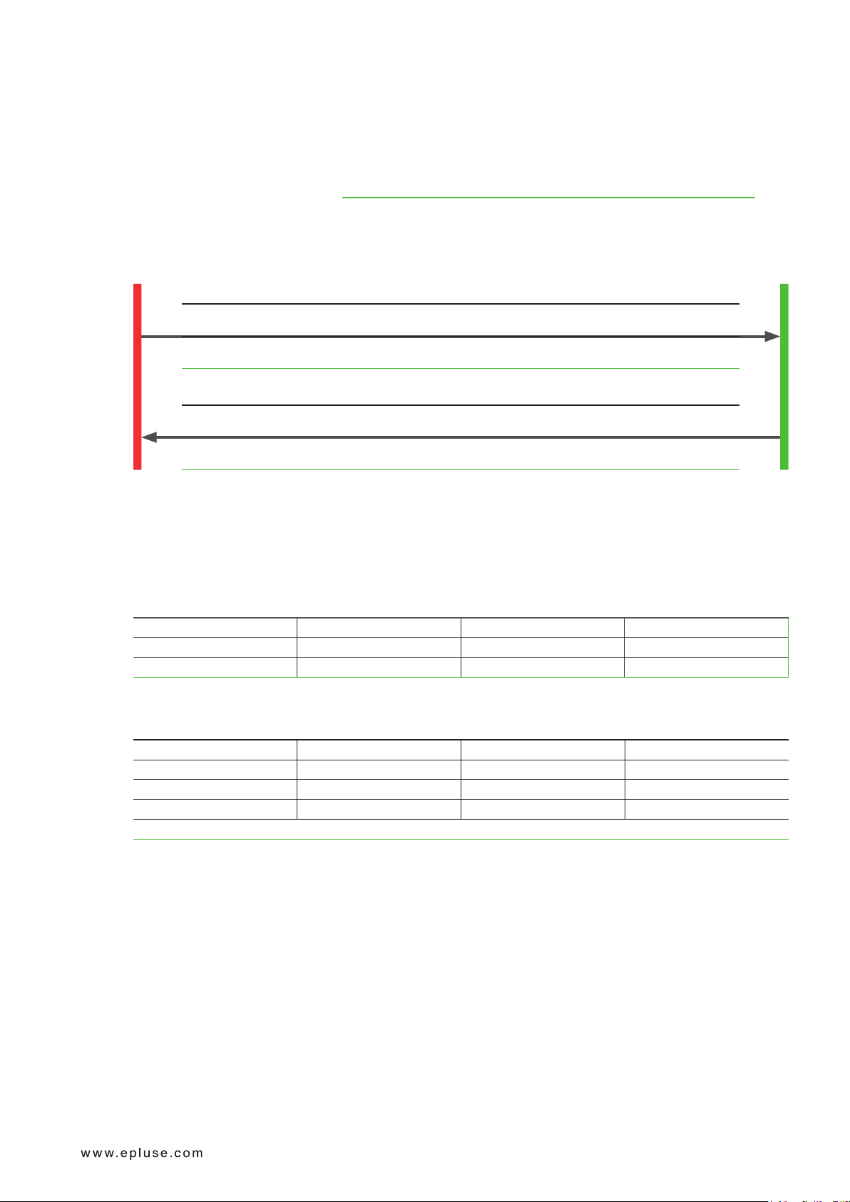
5.4.7. Modbus RTU Example
Example of Modbus RTU command for reading the Temperature (float value) T = 26,953624 °C from the register
0x3EA.
Device EE431; Modbus address 66 [42 in HEX]
Reference document (chapter 6.3): http://www.modbus.org/docs/Modbus_Application_Protocol_V1_1b.pdf.
Read the temperature (FLOAT32) T from register address 0x3EA:
User Manual EE431
Master (e.g. PLC)
Temperature Sensor
Request [Hex]:
Modbus
address
42 03 03 EA 00 02 EB 48
Function
code
Starting
address Hi
Starting
address Lo
Qty. of
registers Hi
Qty. of
registers Lo
CRC
Response [Hex]:
Modbus
address
42 03 04 A1 06 41 D7 3B 04
Fig. 8 Example temperature query
Function
code
Byte
count
Register 1
value Hi
Register 1
value Lo
Register 2
value Hi
Register 2
value Lo
CRC
Decoding of floating point values:
Floating point values are stored according to IEEE754. The byte pairs 1, 2 and 3, 4 are transformed as follows
(numbers taken from T reading Modbus request/response example, Fig. 8):
Modbus response [Hex]
Register 1 Hi Register 1 Lo Register 2 Hi Register 2 Lo
A1 06 41 D7
MMMMMMMM MMMMMMMM SEEEEEEE EMMMMMMM
Fig. 9 Modbus response
IEEE754
Register 2 Hi Register 2 Lo Register 1 Hi Register 1 Lo
41 D7 A1 06
0100 0001 1101 0111 1010 0001 0000 0110
SEEE EEEE EMMM MMMM MMMM MMMM MMMM MMMM
Decimal value: 26.953624725341796875
Fig. 10 Data representation according to IEEE754
6 Maintenance and Service
6.1 Calibration and Adjustment
6.1.1. Definitions
Calibration: The specimen is compared with a reference and its deviation from the reference is documented.
Adjustment: The specimen is brought in line with the reference.
Duct and Immersion Temperature Sensor | 17

6.1.2. Temperature Calibration and Adjustment
Measured value
(or last calibration point LOW)
Depending on the application and the requirements of certain industries, there might arise the need for periodical
temperature calibration or adjustment.
6.1.3. Calibration and Adjustment at E+E Elektronik
Calibration and/or adjustment can be performed in the E+E Elektronik calibration laboratory. For information on
the E+E capabilities in ISO or accredited calibration please see www.eplusecal.com.
6.1.4. Calibration and Adjustment by the User
Depending on the level of accuracy required, the temperature reference can be:
▪ Liquid bath calibrator
▪ Dry block calibrator
▪ Climate chamber
▪ Handheld device (e.g. Omniport30), please see www.epluse.com/omniport30.
Perform offset and 1- or 2-point adjustment via the E+E Product Configuration Software (see below).
User Manual EE431
Measured value
OFFSET
Fig. 11 Offset adjustment
ADJUSTMENT POINT LOW
NEW CHARACTERISTICS
adjusted measured value
FACTORY (or current) CHARACTERISTICS
current measured value
Reference value
1/2 OUTPUT SCALE
ADJUSTMENT POINT HIGH
NEW CHARACTERISTICS
Adjustment point NEW
current measurement
lower limit output scale
Fig. 12 1- or 2-point adjustment
FACTORY (or current) CHARACTERISTICS
Reference value
upper limit output scale
(or last calibration point HIGH)
Duct and Immersion Temperature Sensor | 18

6.2 Repairs and Display Change
PLEASE NOTE
Repairs may be carried out by the manufacturer only. The attempt of unauthorized repair excludes any
warranty claims.
7 Accessories
For further information see datasheet Accessories.
User Manual EE431
Description
Product configuration adapter for 4 - 20 mA version without
display (Available at EE-PCA)
Configuration adapter for display and 0 - 10 V versions without
display
USB configuration adapter for digital output HA011066
E+E Product Configuration Software for digital output and
for 4 - 20 mA version without display
(Free download: www.epluse.com/configurator)
E+E Product Configuration Software
(Free download: www.epluse.com/pcs10) for display and 0 - 10 V
versions without display
Power supply adapter for digital output V03
Conduit Adapter, M16x1.5 auf 1/2" HA011110
Mounting flange HA401101
Immersion well - thread R ½" ISO
Immersion well - thread ½" NPT
Length in mm (inch) 50 (1.97") 100 (3.94") 135 (5.31") 285 (11.22")
Brass HA400101 HA400104 HA400102 HA400103
Stainless steel
Length in mm (inch) 50 (1.97") 100 (3.94") 135 (5.31") 285 (11.22")
Brass HA400111 HA400114 HA400112 HA400113
Stainless steel
Code
See datasheet EE-PCA
HA011023
EE-PCS
PCS10
HA400201 HA400204 HA400202 HA400203
HA400211 HA400214 HA400212 HA400213
Duct and Immersion Temperature Sensor | 19

8 Technical Data
Measurands
Temperature (T) - Active
Measuring range Duct sensor (probe tip)
With immersion well (probe tip)
Accuracy
@ 20 °C (68 °F)
Optional for analogue output
1) Uncertainty of factory calibration at 20 °C ±0.1 °C (68 °F ±0.18 °F).
Temperature (T) - Passive
Measuring range
Duct sensor
Immersion Sensor with Pt and Ni T sensor
Sensor type
Pt100 DIN B R0:100Ω TC: 3.850 x 10⁻³/°C DIN EN 60751
Pt1000 DIN B
NTC10k B3950 R25:10kΩ±0.5%
NTC20k B4286 R25:20kΩ±0.2°C
Ni1000 TK6180 DIN B R0:1000Ω TC: 6180 ppm/K DIN 43760
Ni1000 TK5000 DIN B R0:1000Ω TC: 5000 ppm/K DIN 43760
User Manual EE431
-40 °C…+110 °C (-40...+230 °F)
-40 °C…+130 °C (-40...+266 °F)
±0.25 °C (0.36 °F)
±0.1 °C (±0.18 °F)
-40 °C…+110 °C (-40...+230 °F)
-40 °C…+150 °C (-40...+302 °F)
Nominal resistance Sensitivity Standard
R0:1000Ω TC: 3.850 x 10⁻³/°C
1)
DIN EN 60751
B
: 3989 K
25/85
(B
: 3950 K ± 1.0 %)
25/50
B
: 4286 K
25/85
(B
: 4286 K ± 1.0 %)
25/85
-
-
Outputs
Analogue
Analogue output 0 - 10 V -1mA < IL < 1 mA IL = load current
Digital
Digital interface RS485 (EE431 = 1 Unit Load)
Protocol
Factory settings
Supported Baud rates
Measured data types
Protocol
Factory settings
Supported Baud rates
T Sensor Passive
Sensor connection 2-wire connection
Measuring current, typ. <1 mA (according to technical data of the specific T sensing element)
4 - 20 mA (2-wire) RL ≤500Ω RL = load resistance
Modbus RTU
Baud rate see order information, data bits 8, parity even, 1 stop bit, Modbus address 66
9 600,19 200und38 400
FLOAT32 and INT16
BACnet MS/TP
Baud rate see order information, data bits 8, parity none, 1 stop bit, BACnet address 66
9 600,19 200,38 400,57 600,76 800und115 200
Duct and Immersion Temperature Sensor | 20

User Manual EE431
General
Power supply class III
USA & Canada: Class 2 supply necessary,
max. voltage 30 V DC
for output RS485 and 0 - 10 V
for output
Current consumption,
4 - 20 mA
Voltage output DC supply max. 0.8mA
@ 24 V
Current output According to output current According to output current
Digital interface DC supply typ. 3.5 mA
Electrical connection Screw terminals max. 2.5 mm2 (AWG14)
Cable glands M16x1.5 / M12x1.5 / UL94 V-2
Insulation resistance (probe)
@20 °C (68 °F)
LC-display Available for output A3 and A6
Response time t
Duct sensor at 3 m/s (590 ft/min) air velocity
63
Immersion sensor in liquid water bath
Humidity working range 5…95 %RH, non-condensing
Temperature working range
Storage conditions
Without display
With display
Probe material Stainless steel (1.4571 / 316Ti)
Enclosure Material
Protection rating
Electromagnetic compatibility EN 61326-1 EN 61326-2-3 Industrial environment
Conformity
15 - 35 V DC or 24 V AC ±20 %
10 V DC + RL x 20 mA < V+ < 35 V DC RL = load resistance
with display max. 1.7 mA
AC supply max. 4.6 mA
AC supply typ. 12 mA
rms
rms
with display max. 7 mA
rms
>100MΩ
1 line, switchable between °C / °F or according to order code
Without backlight
Visible area 38 mm x 20 mm (1.5" x 0.8")
<1 min
<30 s
Duct sensor
(probe tip)
-40…+110 °C
(-40...+230 °F)
With immersion well (probe tip) Electronics
Active Passive
-40…+130 °C
(-40...+266 °F)
-40 °C…+150 °C
(-40...+302 °F)
without Display
-40…+70 °C
(-40...+158 °F)
-30…+70 °C (-22...+158 °F)
5…95 %RH, non-condensing
-20...+50 °C (-4...+122 °F)
5…95 %RH, non-condensing
Polycarbonate (PC), UL94 V-0 approved
IP65 / NEMA4X
FCC Part15 Class B ICES-003 Class B
Electronics
with Display
-20...+50 °C
(-4...+122 °F)
Configuration and adjustment
For display and 0 - 10 V
For digital and 4 - 20 mA version without display
PCS10 Product Configuration Software (free download: www.epluse.com/pcs10) and
configuration adapter.
EE-PCS Product Configuration Software (free download: www.epluse.com/configurator)
and configuration adapter.
Duct and Immersion Temperature Sensor | 21

9 Conformity
9.1 Declarations of Conformity
E+E Elektronik Ges.m.b.H. hereby declares that the product complies with the respective regulations listed below:
European directives and standards.
and
UK statutory instruments and designated standards.
Please refer to the product pages at www.epluse.com/ee431 for the Declarations of Conformity.
9.2 FCC Part 15 Compliance Statement
This equipment has been tested and found to comply with the limits for a Class B digital device, pursuant to part
15 of the FCC Rules. These limits are designed to provide reasonable protection against harmful interference
in a residential installation. This equipment generates, uses and can radiate radio frequency energy and, if
not installed and used in accordance with the installation manual, may cause harmful interference to radio
communications. However, there is no guarantee that interference will not occur in a particular installation. If this
equipment does cause harmful interference to radio or television reception, which can be determined by turning
the equipment off and on, the user is encouraged to try to correct the interference by one or more of the following
measures:
User Manual EE431
▪ Reorient or relocate the receiving antenna.
▪ Increase the separation between the equipment and receiver.
▪ Connect the equipment into an outlet on a circuit different from that to which thereceiver is connected.
▪ Consult the dealer or an experienced radio/TV technician for help.
9.3 ICES-003 Compliance Statement
This Class B digital apparatus complies with Canadian ICES-003.
Cet appareil numérique de la classe B est conforme à la norme NMB-003 du Canada.
Duct and Immersion Temperature Sensor | 22

Company Headquarters &
Production Site
E+E Elektronik Ges.m.b.H.
Langwiesen 7
4209 Engerwitzdorf | Austria
T +43 7235 605-0
F +43 7235 605-8
info@epluse.com
www.epluse.com
Subsidiaries
E+E Sensor Technology (Shanghai) Co., Ltd.
T +86 21 6117 6129
info@epluse.cn
E+E Elektronik France SARL
T +33 4 74 72 35 82
info.fr@epluse.com
E+E Elektronik Deutschland GmbH
T +49 6171 69411-0
info.de@epluse.com
E+E Elektronik India Private Limited
T +91 990 440 5400
info.in@epluse.com
E+E Elektronik Italia S.R.L.
T +39 02 2707 86 36
info.it@epluse.com
E+E Elektronik Korea Ltd.
T +82 31 732 6050
info.kr@epluse.com
E+E Elektronik Corporation
T +1 847 490 0520
info.us@epluse.com
Version v1.0 | 11-2023
© Copyright E+E Elektronik Ges.m.b.H. | All rights reserved.
 Loading...