


User Manual
EE08
High-Precision Miniature
Humidity and Temperature Probe
BA_EE08 // v1.4 // Modification rights reserved

E+E Elektronik Ges.m.b.H. does not accept warranty and liability claims neither upon this publication nor in case of improper
treatment of the described products.
The document may contain technical inaccuracies and typographical errors. The content will be revised on a regular basis.
These changes will be implemented in later versions. The described products can be improved and changed at any time
without prior notice.
© Copyright E+E Elektronik® Ges.m.b.H.
All rights reserved.
USA
FCC notice:
This device has been tested and found to comply with the conditions for a category B device according to part 15 of the
FCC rules and regulations. These conditions were designed to provide adequate protection against EMI in a residential
environment. This device generates, uses and can radiate high-frequency energy. If it is not installed and used in accordance
with the operating instructions, it may cause electromagnetic interference to radio communications. However there is no
guarantee that electromagnetic interference will not occur in a particular installation. If the device does cause electromagnetic
interference to radio or television reception (this can be determined by turning the device off and on), the user is advised to
remedy the interference with the following measures:
• Reorient or relocate the receiving antenna.
• Increase the distance between the device and receiver.
• Connect the device to a different circuit to that of the receiver.
• Consult the dealer or an experienced radio/TV technician.
Caution:
Any changes to the device not expressly approved by an EMI representative could void the user‘s authority to operate this
device.
CANADA
ICES-003 notification:
This category B device complies with Canadian standard ICES-003.

INHALT
1 General ................................................................................................................................................. 4
1.1 Explanation of Symbols .................................................................................................................................4
1.2 Safety instructions .........................................................................................................................................4
1.2.1 General Safety Instructions .................................................................................................................................. 4
1.2.2 Intended Use ........................................................................................................................................................4
1.2.3 Mounting, Start-up and Operation ........................................................................................................................ 5
1.3 Environmental Aspects ..................................................................................................................................5
2 Scope of Supply ..................................................................................................................................5
3 Product Description ............................................................................................................................ 5
3.1 General ..........................................................................................................................................................5
3.2 Dimensions ....................................................................................................................................................6
3.3 Electrical Connection .....................................................................................................................................6
4 Installation ...........................................................................................................................................7
5 Maintenance ......................................................................................................................................... 7
6 Calibration / Adjustment ..................................................................................................................... 7
7 Accessories / Spare Parts ..................................................................................................................8
8 Technical Data .....................................................................................................................................8

1 General
This user manual serves for ensuring proper handling and optimal functioning of the device. The user
manual shall be read before commissioning the equipment and it shall be provided to all staff involved
in transport, installation, operation, maintenance and repair. The user manual may not be used for the
purposes of competition without the written consent of E+E Elektronik® and may not be forwarded to
third parties. Copies may be made for internal purposes. All information, technical data and diagrams
included in these instructions are based on the information available at the time of writing.
Disclaimer
The manufacturer or his authorized agent can be only be held liable in case of willful or gross
negligence. In any case, the scope of liability is limited to the corresponding amount of the order issued
to the manufacturer. The manufacturer assumes no liability for damages incurred due to failure to
comply with the applicable regulations, operating instructions or the specified operating conditions.
Consequential damages are excluded from the liability.
1.1 Explanation of Symbols
This symbol indicates safety information.
It is essential that all safety information is strictly observed. Failure to comply with this information can
lead to personal injuries or damage to property. E+E Elektronik® assumes no liability if this happens.
This symbol indicates instructions.
The instructions shall be observed in order to reach optimal performance of the device.
1.2 Safety instructions
1.2.1 General Safety Instructions
The device and mainly the filter cap shall not be exposed to unnecessary mechanical stress.
When replacing the filter cap make sure not to touch the sensing elements.
The device must be operated with the filter cap on at all times.
For sensor cleaning please see “Cleaning Instructions” at www.epluse.com/ee08.
Installation, electrical connection, maintenance and commissioning shall be performed by qualified
personnel only.
Use the EE08 only as intended and observe all technical specifications.
Do not use EE08 in explosive atmosphere or for measurement of aggressive gases.
This device is not appropriate for safety, emergency stop or other critical applications where device
malfunction or failure could cause injury to human beings.
1.2.2 Intended Use
The EE08 is intended for the humidity (RH) and temperature (T) measurement in applications that
require accurate measurement over wide RH and T ranges. It must not be applied in hazardous
environment with agressive or flammable gases or in explosive areas. For use outdoors and/or in
meteorolgy, optional radiation shields are available. Please refer to chapter 3 Product Description.
The use of the EE08 in any other way than described in this manual bears a safety risk for people and
the entire measurement installation and is therefore not allowed.
The manufacturer cannot be held responsible for damages as a result of incorrect handling, installation,
and maintenance of the equipment.
In order to avoid damage to the instrument or health hazards, the measuring equipment must never be
manipulated with tools that are not specifically described in this manual.
The sensor may only be utilized in accordance with the conditions defined in the technical data.
Otherwise, measurement inaccuracies will occur and equipment failures cannot be ruled out.
The steps recommended by the manufacturer for installation, inspections and maintenance work must
be observed and carried out for the safety of the user and for the functionality of the equipment.
4
User Manual for EE08 Humidity / Temperature Probe

Unauthorized product modification leads to loss of all warranty claims. This may be accomplished only
with an explicit permission of E+E Elektronik®!
1.2.3 Mounting, Start-up and Operation
The EE08 humidity and temperature probe has been produced under state of the art manufacturing
conditions, has been thoroughly tested and has left the factory after fulfilling all safety criteria. The
manufacturer has taken all precautions to ensure safe operation of the device. The user must ensure
that the device is set up and installed in a manner that does not have a negative effect on its safe
use. The user is responsible for observing all applicable safety guidelines, local and international, with
respect to safe installation and operation on the device. This user manual contains information and
warnings that must be observed by the user in order to ensure safe operation.
Mounting, start-up, operation and maintenance of the device may be performed by qualified staff
only. Such staff must be authorized by the operator of the facility to carry out the mentioned activities.
The qualified staff must have read and understood this user manual and must follow the instructions
contained within.
All process and electrical connections shall be thoroughly checked by authorized staff before putting
the device into operation.
Do not install or start-up a device supposed to be faulty. Make sure that such devices are not
accidentally used by marking them clearly as faulty.
A faulty device may only be investigated and possibly repaired by qualified, trained and authorized
staff. If the fault cannot be fixed, the device shall be removed from the process.
Service operations other than described in this user manual may only be performed by the
manufacturer.
1.3 Environmental Aspects
Products from E+E Elektronik® are developed and manufactured observing of all relevant
requirements with respect to environment protection. Please observe local regulations for the device
disposal.
For disposal, the individual components of the device must be separated according to local recycling
regulations. The electronics shall be disposed of correctly as electronics waste.
2 Scope of Supply
EE08 probe according to ordering guide
Inspection certificate according to DIN EN10204-3.
3 Product Description
3.1 General
The EE08 is a probe for the highly accurate measurement of humidity (RH) and temperature (T) over
wide RH and T ranges of 0...100 % RH and -40...80 °C (-40...176 °F).
Typical application fields of the probe are
Meteorology / weather stations
Humidity / temperature data logging
Incubators
Fermentation chambers
Green houses
Snow machines
Dry storage facilities
There are two types of probe, the EE08 with cable (type E8) up to 5 m (16.4 ft) length and the EE08 with
connector (type E11). For the latter, connection cables with length 1.5 / 3 / 5 / 10 m (5 / 10 / 16.4 / 32.8 ft) are
available as accessory.
User Manual for EE08 Humidity / Temperature Probe
5

For outdoor operation the use of an appropriate radiation shield is of paramount importance. The
EE08 is compatible with rotational symmetric radiation shields which protect it against rain, snow and
overheating caused by direct sunlight (available as accessory HA010502, suitable for type E8 and
HA010506, suitable for type E11).
3.2 Dimensions
EE08 with cable (Type E8)
EE08-MxE8xxx
61 (2.4)
M12x1
EE08 with connector (Type E11)
EE08-MxE11xxx
83 (3.27)
M16x1.5
61 (2.4)
71 (2.8)
∅12 (0.47)
25 (1)
73 (2.87)
∅12 (0.47)
Fig. 1 Dimensions of EE08 in mm (inch)
Ø105 (4.1)
174 (6.9)
5
Ø5
(Ø0.2)
20
20
(0.8)
1.5
44
(1.7)
94 (3.7)
22
(0.9)
1.5
(0.06)
122 (4.8)
Fig. 2 Dimensions of optional radiation shields HA010502 and HA010506 in mm (inch)
connector M12x1
(8 poles)
3.3 Electrical Connection
EE08 with cable: EE08-M1xE8xxx
GND pink pink
T-out grey not connected (grey)
RH-out yellow yellow
SCL
SDA brown brown
+UB red red
T-passive not connected (white) white, black
T-passive not connected (blue) blue, violet
}
E2interface
EE08-M6xE8xxx
T active
T passive, 4 wire
green green
6
User Manual for EE08 Humidity / Temperature Probe

EE08 with connector: EE08-MxE11xxx
T active / passive, 2 wire
1 T passive
2 SDA
3 SCL green
4 RH out yellow
5 T out grey
6 GND pink
7 T passive
8 +UB red
1) not connected for T active versions (M1)
The manufacturer cannot be held responsible for personal injuries or damage to property as a result of
incorrect handling, installation, wiring, power supply and maintenance of the device.
Ground connection:
A low impedance connection between the shield of the connection cable and the ground potential is
important for the flawless operation of the EE08.
E2 Voltage Level:
Please observe an E2 voltage level of 3.3 V / ±0.1 V on the data lines.
1)
E2-
}
interface
1)
Assignment of M12 connection cable
(HA010322, HA010323, HA010324, HA010325)
white
brown
blue
4 Installation
The follwing mounting types are possible:
Wall mount with the help of a mounting clip, available as accessory HA010211.
Outdoor operation with radiation shield: wall mount or pole mount. Please mind the mounting
instructions included in the manuals of HA010502 and HA010506.
5 Maintenance
The use in dirty, dusty, polluted environment might arise the need for cleaning the sensing head and
replacing the filter cap. In such a case please see the Cleaning Instructions at www.epluse.com/ee08.
Do not touch the humidity sensor!
6 Calibration / Adjustment
Definitions
Calibration documents the accuracy of a measurement device. The device under test (specimen) is
compared with the reference and the deviations are documented in a calibration certificate. During
the calibration, the specimen is not changed or improved in any way.
Adjustment improves the measurement accuracy of a device. The specimen is compared with the
reference and brought in line with it. An adjustment can be followed by a calibration which documents
the accuracy of the adjusted specimen.
To carry out a one point or a two point calibration / adjustment, the E2 / RS232 converter (available as
an accessory, order code HA011005) and the EE-PCS Product Configuration Software are necessary.
The EE-PCS is freely available at www.epluse.com/ee08.
User Manual for EE08 Humidity / Temperature Probe
7
7 Accessories / Spare Parts
M12 connection cable for type E11, length 1.5 m (5 ft) HA010322
M12 connection cable for type E11, length 3 m (10 ft) HA010323
M12 connection cable for type E11, length 5 m (16.4 ft) HA010324
M12 connection cable for type E11, length 10 m (32.8 ft) HA010325
Radiation shield for Type E8 HA010502
Radiation shield for Type E11 HA010506
Wall mounting clip Ø12 mm HA010211
Protection cap for Ø12 mm probe HA010783
M12 female socket with wires HA010703
M12 female cable connector assembly possible HA010704
Metal grid filter HA010113
Cconfiguration cable HA011005
EE-PCS free download at www.epluse.com/ee08
8 Technical Data
Measurands
Relative Humidity
Measuring range 0...100 % RH
Accuracy at 23 °C (73 °F) for RH ≤ 90 % ±2 % RH
and nominal voltage1) for RH > 90 % ±3 % RH
Temperature dependence, typ. 0.03 % RH/°C (0.02 % RH/°F)
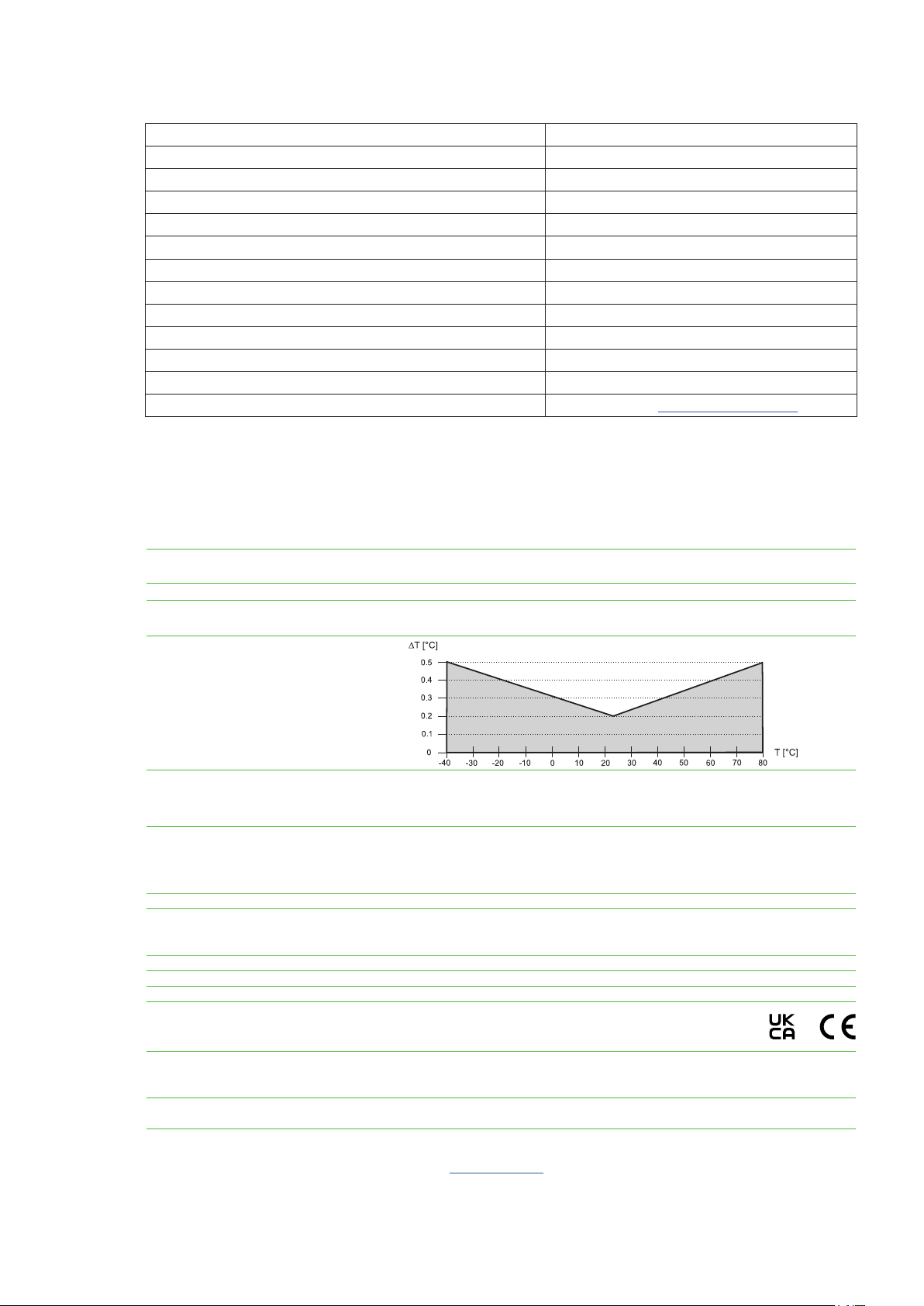
Temperature
Measuring range -40...80 °C (-40...176 °F)
Accuracy
at nominal voltage1)
Outputs
Analogue 0 - 1 V / 0 - 2.5 V / 0 - 5 V / 0 - 10 V -0.2mA < I
Digital interface E2 interface
2)
< 0.2 mA
L
General
Supply voltage for output 0 - 1 V / 0 - 2.5 V V1: 4.5 - 15 V DC V2: 7 - 30 V DC
for output 0 - 5 V V2: 7 - 30 V DC
for output 0 - 10 V V2: 12 - 30 V DC
Current consumption, typ. < 1.3 mA
Electrical connection M12x1, 8 poles
Cable PVC 8 x 0.14 mm² (M1 models)
Cable PVC 10 x 0.14 mm² (M6 models)
Filter Metal grid
Protection rating IP65
Enclosure material Polycarbonate
Electromagnetic compatibility EN 61326-1 EN 61326-2-3
Industrial Environment
FCC Part15 Class B ICES-003 Class B
Operating and storage conditions -40...80 °C (-40...176 °F)
0...100 % RH (operation)
0...95 % RH, non-condensing (storage)
Adjustment With EE-PCS (Product Configuration Software, free download)
and configuration adapter
1) The accuracy statement includes the uncertainty of the factory calibration with an enhancement factor k=2 (2-times standard deviation). The accuracy was calculated in
accordance with EA-4/02 and with regard to GUM (Guide to the Expression of Uncertainty in Measurement);
nominal voltage V1 = 12 V DC, V2 = 24 V DC
2) E2 Voltage Level = 3.3 V / ±0.1 V, for further support literature refer to www.epluse.com/ee08.
8
User Manual for EE08 Humidity / Temperature Probe

HEADQUARTERS
E+E Elektronik Ges.m.b.H.
Langwiesen 7
4209 Engerwitzdorf
Austria
Tel.: +43 7235 605-0
E-mail: info@epluse.com
Web: www.epluse.com
SUBSIDIARIES
E+E Elektronik China
18F, Kaidi Financial Building,
No.1088 XiangYin Road
200433 Shanghai
Tel.: +86 21 6117 6129
E-mail: info@epluse.cn
E+E Elektronik France
47 Avenue de l‘Europe
92310 Sèvres
Tel.: +33 4 74 72 35 82
E-mail: info@epluse.fr
E+E Elektronik Germany
Obere Zeil 2
61440 Oberursel
Tel.: +49 6171 69411-0
E-mail: info@epluse.de
E+E Elektronik India
801, Sakhi Vihar Road
400072 Mumbai
Tel.: +91 990 440 5400
E-mail: info.in@epluse.com
E+E Elektronik Italy
Via Alghero 17/19
20128 Milano (MI)
Tel.: +39 02 2707 86 36
E-mail: info@epluse.it
E+E Elektronik Korea
Suite 2001, Heungdeok IT
Valley Towerdong, 13,
Heungdeok 1-ro, Giheung-gu
16954 Yongin-si, Gyeonggi-do
Tel.: +82 31 732 6050
E-mail: info@epluse.co.kr
E+E Elektronik USA
333 East State Parkway
Schaumburg, IL 60173
Tel.: +1 847 490 0520
E-mail: office@epluse.com
 Loading...