

EED Q-DISP-C, Q-DISP-C-x-x-x-x User Manual
www.qeed.it
info@qeed.it
eed
eed
quality electronic design
www.dem-it.com
ANALOG SIGNAL DISPLAY Q-DISP-C
ANALOG SIGNAL DISPLAY Q-DISP-C
Sept 2013
Q-DISP-C-x-x-x-x
Q-DISP-C-L (Low Voltage Supply)
Q-DISP-C-H (High Voltage Supply)
Q-DISP-C-x-R (n°1 Relay output)
Q-DISP-C-x-R-R (n°2 Relays output)
Q-DISP-C-x-R-R-R (n°3 Relays output)
Q-DISP-C-x-AO (n°1 Analog Output)
Q-DISP-C-x-AO-R (n°1 AO, n°1 Relay)
Q-DISP-C-x-AO-R-R (n°1AO, n°2 Relays)
Q-DISP-C-x-AO-AO (n°2 AO)
Q-DISP-C-x-AO-AO-R (n°2 AO, n°1 Relay)
Q-DISP-C-x-AO-AO-AO (n°3 AO)
DEM SPA - Z.I. Villanova, 20 -32013 Longarone (BL) Italy - tel. +39 0437 761021 -fax +39 0437 760024 - P.Iva 00691730253
The displays Q-DISP-C, prepared for
mounting on the back panel, 96x48mm, will
allow you to count and totalize.
It is possible to have a high power or low
voltage AC / DC and have up to congurable
outputs of relay outputs and analog outputs
USER’s MANUAL

Q-DISP-C
User’s Manual
Page 2
1. Meter Q-DISP-C
Panel meter 96x48mm counter, ratemeter, periodmeter
Panel meter congurable as impulse counter, ratemeter and
periodmeter. Accepts wide range of signal types such as
Push-pull, NPN, PNP, Namur, TTL, inductive, mechanical,
... also monodirectional and bidirectional encoder signals
(quadrature signals).
Highly congurable, with pull-up/pull-down resistors, trigger
levels, pulse detection on raising or falling edge, excitation
voltage and antirrebound lters. ‘Trigger Sense’ utility for easy
trigger level adjustment.
Scalable reading by congurable multiplier and divider factors (1 to 999999). Congurable decimal point position.
Resolution 6 digits (999999/-199999).
Excitation voltage congurable to 5V, 9V, 15V and 18V.
Up to 3 relay outputs controlled from the instrument alarms,
can be increased to 6 relay outputs (with simplied functionality, see section 2). Congurable direct access to setpoint
values modication on key UP (5).
Standard 96x48mm DIN size. Universal AC and DC power
options. Up to three control and/or signal retransmission
modules. IP54 front protection, with optional IP65.
Connections via plug-in screw terminals and conguration via
three front push-buttons. For industrial applications.
Counter modes
Counter functionality allows to choose between 5 counting
modes (simple counter, quadrature counter, counter with
inhibit control, differential counter and counter with add/substract control). Instrument has two impulse input channels
(A and B) and selectable ascending or descending counting
modes.
Reset function is accessible from rear terminal and front
push-button. The front reset can be enabled or disabled. Congurable preset value. Alarm activation can be associated
to an action : ‘reset to zero’, ‘return to preset’ or ‘no action’.
Relays activation and deactivation times are independent
and congurable.
Alarm functions with ‘reset to zero’ or ‘return to preset’ create
a continuous counting cycle (instrument cycles from ‘preset
value’ to ‘alarm value’). Instrument provides a internal cycle
counter, accessible to the operator.
Memory retention in case of power loss or deactivation. When
power is back again, instrument recovers the last reading
and conguration.
Maximum counting frequency is 250 KHz in ‘FAST’ mode.
Ratemeter mode
Ratemeter function allows to choose between normal ratemeter (one single input channel) or bidirectional ratemeter
(quadrature ratemeter) with detection of clockwise / counterclockwise sense of turn.
In ratemeter mode, the instrument counts the number of
impulses during a xed period of time, and calculates the
frequency.
For low frequency applications, a special ‘SLOW’ mode is
available, which offers the fastest response time for low frequency applications. See section 1.13 for more information.
Recursive lter ‘Average’ to stabilize unstable readings.
Maximum frequency in ratemeter mode is 900KHz and
minimum frequency (with ‘SLOW’ mode activated) is 0.001
Hz (1mHz).
Periodmeter mode
Periodmeter mode detects the signal time between impulses.
For long period applications, a special ‘SLOW’ mode is available which offers the fastest response time for low frequency
applications. See section 1.13 for more information.
Q-DISP
C H
Model Power
-H
(85-265 Vac/dc)
-L (11-60 Vdc
and 24/48 Vac)
- - - ---
Option1
-R
(1 relay)
-AO ( Analogue output)
- (empty)
- ---
Option2
-R
(1 relay)
-AO ( Analogue output)
- (empty)
- ---
Option3
-R
(1 relay)
-AO ( Analogue output)
- (empty)
1.1 Order reference

Q-DISP-C
User’s Manual
Page 3
Index
1. Meter Q-DISP-C . . . . . . . . . . . . . . . . . . . . 2
1.1 Order reference . . . . . . . . . . . . . . . . . . . 2
1.2 Start-up . . . . . . . . . . . . . . . . . . . . . . . 3
1.3 Front view. . . . . . . . . . . . . . . . . . . . . . 4
1.4 Power connections . . . . . . . . . . . . . . . . . 4
1.5 Sensor conguration and connections . . . . . . . 4
1.6 Rear view . . . . . . . . . . . . . . . . . . . . . . 4
1.7 Signal connections . . . . . . . . . . . . . . . . . 4
1.8 Technical data. . . . . . . . . . . . . . . . . . . . 5
1.8 Technical data (cont.) . . . . . . . . . . . . . . . . 5
1.9 Mechanical dimensions (mm). . . . . . . . . . . . 5
1.10 Conguration menu . . . . . . . . . . . . . . . . 6
1.10 Conguration menu (cont.) . . . . . . . . . . . .7
1.10.1 Menu Cnf.1 - Counter . . . . . . . . . . . . . . 8
1.10.2
Menu
Cnf.2 -
Counter
quadrature . . . . . . . . . . 8
1.10.3
Menu
Cnf.3 -
Counter
+ Inhibit . . . . . . . . . . . 8
1.10.4 Menu Cnf.4 - Counter add/substract . . . . . . . . 8
1.10.5
Menu
Cnf.5 -
Counter
differential . . . . . . . . . . 8
1.10.6 Menu Cnf.6 - Ratemeter. . . . . . . . . . . . . 8
1.10.7
Menu
Cnf.7 - Ratemeter quadrature . . . . . . . . . 9
1.10.8 Menu Cnf.8 - Periodmeter . . . . . . . . . . . . 9
1.11 Default factory conguration. . . . . . . . . . . . 9
1.12 Conguration menu descriptions . . . . . . . . 10
1.12.1 Function mode . . . . . . . . . . . . . . . . . 10
1.12.2 Decimal point. . . . . . . . . . . . . . . . . 10
1.12.3 “cnF.1” - Counter . . . . . . . . . . . . . . . 10
1.12.4 “cnF.2” - Counter quadrature . . . . . . . . . 10
1.12.5 “cnF.3” - Counter + Inhibit . . . . . . . . . . 10
1.12.6 “cnF.4” - Counter + Control A/S . . . . . . . .10
1.12.7 “cnF.5” - Counter differential . . . . . . . . . 11
1.12.8 “cnF.6” - Ratemeter . . . . . . . . . . . . . 11
1.12.9 “cnF.7” - Ratemeter quadrature . . . . . . . . 11
1.12.10 “cnF.8” - Periodmeter . . . . . . . . . . . . 11
1.12.11 Menu Sensor . . . . . . . . . . . . . . . . 12
1.12.12 Menu Alarms . . . . . . . . . . . . . . . . 12
1.12.13 Menu Tools . . . . . . . . . . . . . . . . . 13
1.12.14 Menu OptX - Options . . . . . . . . . . . . 13
1.13 Mode ‘SLOW’ . . . . . . . . . . . . . . . . . . 13
1.14 Mode ‘FAST’. . . . . . . . . . . . . . . . . . . 13
1.15 ‘Trigger Sense’. . . . . . . . . . . . . . . . . . 13
1.16 Messages and errors . . . . . . . . . . . . . . 14
1.17 Operating the menus . . . . . . . . . . . . . . 14
1.18 Accessing the instrument . . . . . . . . . . . . 14
1.19 Warranty. . . . . . . . . . . . . . . . . . . . . 15
1.20 Installation precautions . . . . . . . . . . . . . 15
2. Control modules . . . . . . . . . . . . . . . . . . . 15
2.1 Module R . . . . . . . . . . . . . . . . . . . . . 15
2.2 Module AO . . . . . . . . . . . . . . . . . . . . 15
1.2 Start-up
To start-up the instrument, take the following steps into consideration :
1. Input signal connections à see section 1.5 y 1.7
2. Power connections à see section 1.4
3. Sensor conguration àsee section 1.12.11 (menu
“SnSr”). Select from the “Auto” menu entry one of the listed
sensors, to congure the default values for that sensor
(values indicated in Table1 (see section 1.5)). Values can
also be manually congured :
3.1. pull-up/pull-down resistors on channel A, B and Reset
3.2. trigger level (shared for channels A and B). (Trigger
level for reset is xed at 2,5V).
3.3. antirrebound lter (shared for channels A and B)
3.4. excitation voltage value
4. Select the function mode (counter, ratemeter, periodmeter,
...) and values for multiplier and divider (menu “Func”).
4.1. function mode àsee section 1.12.1
4.2. decimal point position “dP” àsee section 1.12.2
4.3. multipliers and dividers àsee sections 1.12.3
to 1.12.10 (menu “cnF.X”) depending on the function mode
selected.
5. Advanced conguration
To modify setpoint values, presets, activation edges, etc ...
see next sections in this document.
Q-DISP-C
User’s Manual
Page 4
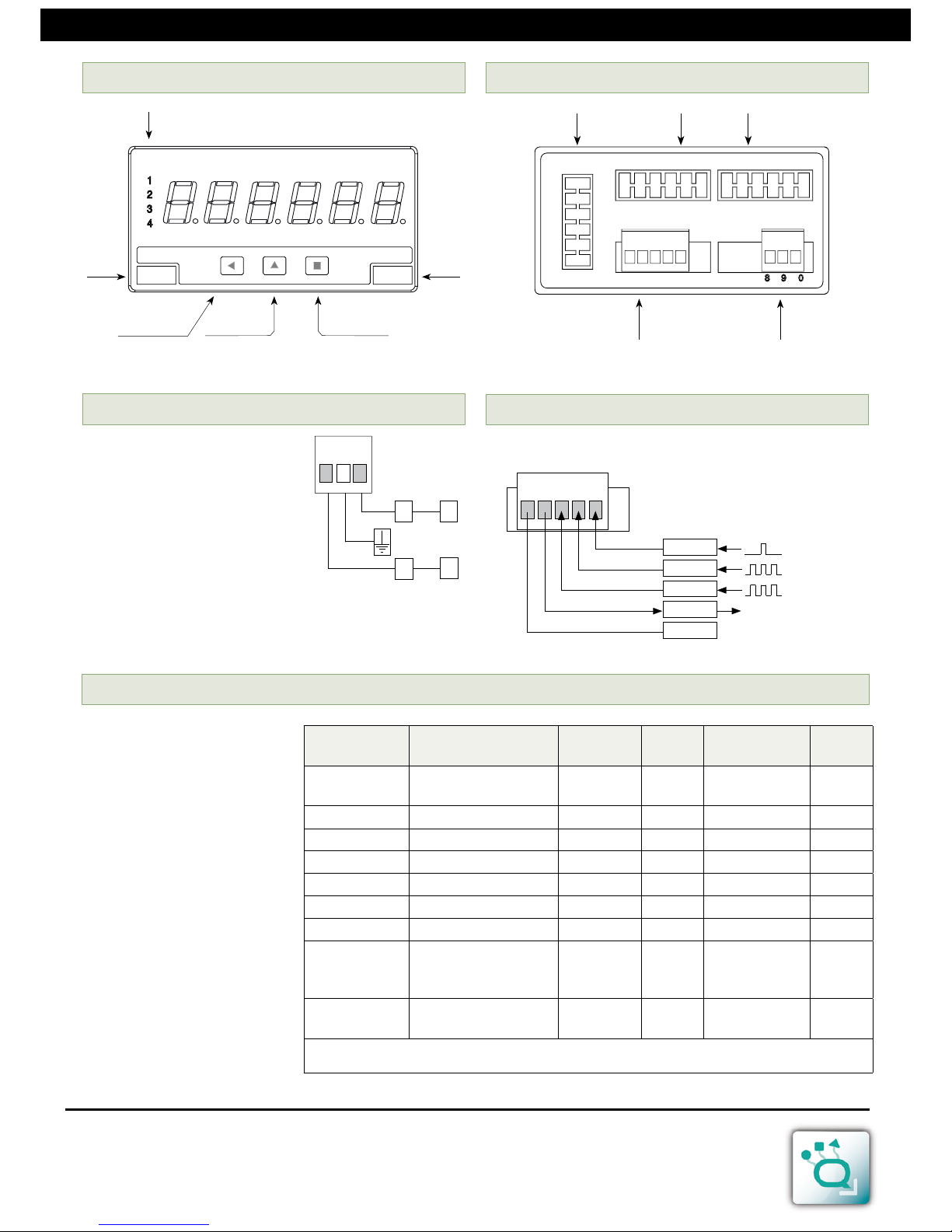
Button ‘UP’
Logo
Alarms
Units
Button ‘SQ’
Button ‘LE’
Access to
‘Configuration menu’
Quick access
1.3 Front view
Front reset for
counter mode
Signal
Option1 Option2Option3
Power
1.6 Rear view
1 2 3 4 5
1 2 3 4 5
1.7 Signal connections
0V
Channel A
Vexc
Channel B
Reset
Earth connection - Although a terminal is
offered for earth connection, the connection is optional. The instrument does not
need this connection for correct functioning nor for compliance with the security
regulations.
Fuse - To comply with security regulation
61010-1, add to the power line a protection
fuse acting as disconnection element, easily accessible to the operator and identied
as a protection device.
~
~
+
-
8 9 0
1.4 Power connections
Power “H” fuse 250mA time-lag
Power “L” fuse 400mA time-lag
Sensor
Connections
(for channel A)
Pulls Vexc
Antirrebound
lter
Trigger
Mechanical
contact
0V Channel A Pull-up No 100mSec. 2,5V
Namur Channel A Vexc Pull-down 9V No 3,0V
NPN 2 wires 0V Channel A Pull-up 18V No 2,5V
NPN 3 wires 0V Channel A Vexc Pull-up 18V No 2,5V
PNP 2 wires 0V Channel A Pull-down 18V No 2,5V
PNP 3 wires 0V Channel A Vexc Pull-down 18V No 2,5V
Push-pull 0V Channel A Vexc No 18V No 2,5V
TTL
CMOS
Pick-up
0V Channel A No 5V No 2,5V
AC <30V
Inductive
0V Channel A No No No 0V
Table1 - Conguration and connections for different sensor types
Examples for channel A connections
1.5 Sensor conguration and connections
Examples of connections and
congurations for different sensor types.
Connections are indicated for
channel A. For channel B connect the same way, but in channel B.
Note - values indicated on Table1
are usual values. Conrm with
your sensor datasheet the specications that apply and adapt the
conguration values and connections as needed.
Q-DISP-C
User’s Manual
Page 5
Digits 6
Type 7 segments, red
Height 14 mm
Display maximum 999999
Display minimum -199999
Decimal point selectable 8.8.8.8.8.8.
Overrange congurable ‘ash’, ‘reset’, ‘preset’
Underrange congurable ‘ash’, ‘reset’, ‘preset’
Signals accepted impulses and frequencies
Connections 2 wires, 3 wires and quadrature
Signal types Push-pull, NPN, PNP, Namur,
Pick-up, TTL, inductive, mechani-
cal, quadrature, ...
Maximum Vdc at input ±30Vdc
Input impedance 2K4 if pull resistors on
470K if pull resistors off
Maximum and minimum frequencies
Counter
with ‘FAST’ mode max. 250 KHz
without ‘FAST’ mode max. 9 KHz
Counter quadrature x1 max. 17 KHz
Counter quadrature x2 max. 16 KHz
Counter quadrature x4 max. 11 KHz
Counter + inhibit max. 9 KHz
Counter + control A/S max. 9 KHz
Counter differential max. 9 KHz
Ratemeter max. 900 KHz
with ‘SLOW’ mode max. 200Hz
with ‘SLOW’ mode min. 1mHz
Ratemeter quadrature x1 max. 17 KHz
Ratemeter quadrature x2 max. 16 KHz
Ratemeter quadrature x4 max. 11 KHz
Periodmeter max. 900 KHz
with ‘SLOW’ mode max. 200 Hz
with ‘SLOW’ mode min. 1mHz
(1000 seconds)
Accuracy
Of the quartz oscillator ±0.01%
Thermal drift 20ppm/ºC
Excitation voltage
Congurable to 5V, 9V, 15V, 18V
Current 70mA max.
Protection yes, current limited to 70mA max.
Refresh
Display refresh 15 / second
Number of readings 100 / second in counter modes
Number of readings 1 / GATE in rate and period modes
Power
Power “H” 85 to 265 Vac/dc
Power “L” 11 to 60 Vdc and 24/48Vac
Consumption <4W
Isolation 3500Veff for power “H”
(tested 60 seconds) 2000Veff for power “L”
Conguration 3 frontal push buttons
(rear jumper for coupling selection)
Functions available
Multiplier and divider yes, congurable
Preset yes, congurable
Edge selection yes, congurable
‘SLOW’ frequency mode yes, congurable
Recursive lter yes, congurable
Pull resistors yes, congurable
Trigger levels yes, congurable
Excitation voltage yes, congurable
Antirrebound lter yes, congurable
Memory yes, maximum ,minimum, cycles
Memory of counter yes, recovers data on power loss
Reset congurable yes, front and/or rear reset and/or
assigned to setpoint
Zeros to the left yes, congurable
Password yes, congurable
Brightness control yes, 5 levels
Optional boards maximum 3 (see section 2)
Mechanical
Mounting panel
Connections plug-in screw terminals
Weight <150 grams
Housing materials ABS, polycarbonate
Front size 96x48mm
Panel cut-out 92x44mm
Deep from panel 91mm (including terminal)
Protection IP54 standard
IP65 optional (Front sealed.
Opening the front breaks the seal)
Temperature Operation 0 to 50ºC
Temperature Storage –20 to +70ºC
Warm-up 15 minutes
1.8 Technical data 1.8 Technical data (cont.)
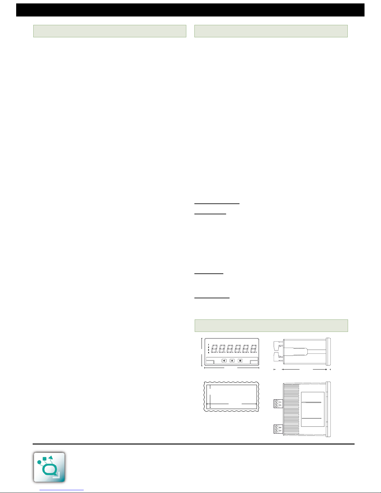
44
92
Panel
cut-out
96
48
16
8
75
1.9 Mechanical dimensions (mm)
 Loading...