

Page 1

OMNIPORT 30
Hand-Held
Meter
BA_Omniport30_e // v1.5 / Subject to technical changes // 193989
Operating Manual
Page 2

The operating manual is used to ensure optimal operation and functioning of the device.
E+E Elektronik® Ges.m.b.H. provides no warranty of any kind on this publication and no liability for improper use of the products described.
To ensure perfect functioning, these operating instructions must be read carefully and
observed before the transmitter is commissioned. These instructions must be provided to all
persons responsible for mounting, commissioning, operation, inspection, maintenance and
repair.
These operating instructions must not be used for the purposes of competition without our written permission and must not be forwarded to third parties. Copies may be made for internal
purposes. All information, technical data and technical diagrams included in these instructions
were correct in accordance with the data available at the time of writing.
The company E+E Elektronik GmbH reserves the right to make modifications at any time and
without prior notification, with no update requirement on models produced before the modification date. For this reason, we request that you contact our customer service department, quoting the device number, designation and type given on the nameplate.
© Copyright E+E Elektronik Ges.m.b.H.
All rights reserved.
2
Page 3

Inhaltsverzeichnis
1. NOTES REGARDING THE MANUAL 4
1.1 Preface 4
1.2 Symbols 4
1.3 Definitions 4
2. INFORMATION ABOUT THE DEVICE 5
2.1 Description of the device 5
2.2 Device depiction 5
2.3 Technical Data 6
2.4 Scope of supply 6
3. SAFETY 6
3.1 Intended use 6
3.2 Improper use 7
3.3 Personnel qualifications 7
3.4 Residual risks 7
4. TRANSPORT AND STORAGE 8
4.1 Transport 8
4.2 Storage 8
5. OPERATION 9
5.1 Inserting the batteries 9
5.2 Switching on 9
5.3 Switching off 9
5.4 Description of screen elements 9
5.5 "Measuring mode – Air pressure" screen (integrated probe) 11
5.6 "Measuring mode – Air pressure – Automatic measurement" screen
(integrated probe) 12
5.7 "Customer Adjustment - Air pressure" screen 13
5.8 "Measuring mode - Flow rate" screen 14
5.9 "Measuring mode – Flow rate – Automatic measurement" screen 15
5.10 "Measuring mode – Flowrate – Measuring range" screen 16
5.11 "Customer Adjustment - Flowrate" screen 17
5.12 "Measuring mode – Humidity" screen 18
5.13 "Measuring mode – Humidity – Automatic measurement" screen 19
5.14 "Customer adjustment - Humidity" screen 20
5.15 "Measuring mode – Moisture in oil" screen 21
5.16 "Measuring mode – Moisture in oil – Automatic measurement" 22
5.17 "Oil parameters – Moisture in oil" screen 23
5.18 "Customer adjustment – Moisture in oil" screen 24
5.19 "Measuring mode – CO
5.20 "Measuring mode – CO2 – Automatic measurement" screen 26
5.21 "Customer Adjustment - CO2" screen 27
5.22 Explanation of the measured values 28
5.23 "Archive" screen 30
5.24 "Settings" screen 31
5.25 Performing measurement (exemplary using probe for temperature 33
5.26 and air flow measuring) 33
5.27 Shut down procedure 33
6. PC-SOFTWARE 34
6.1 Installation conditions 34
6.2 Installing the PC software 34
6.3 Starting the PC software 34
7. ERRORS AND FAULTS 35
7.1 Status and error codes 35
8. MAINTENANCE 35
8.1 Maintenance and care intervals 35
8.2 Activities for before the start of maintenance 36
8.3 Visual inspection of the device 36
8.4 Cleaning the device 36
8.5 Maintenance of humidity probes 36
9. DISPOSAL 37
10. DECLARATION OF CONFORMITY 37
" screen 25
2
3
Page 4
1. NOTES REGARDING THE MANUAL
1.1 Preface
The operating manual only describes the multifunctional hand-held and its intended use.
Detailed descriptions of the sensors and optional accessories as well as tips for proper and
practical use of the multifunctional hand-held are not included in this manual.
The current version of the manual and the general catalogue can be found at:
www.epluse.com
1.2 Symbols
Hazardous electric current!
Warns about hazards from electric current which can lead to injuries or even death.
Danger!
Warns of a hazard which can lead to personal injury.
Caution!
Warns of a hazard which can lead to damage to property.
1.3 Definitions
Concept Meaning
SDI connection
SmartGraph3
Serial Digital Interface; digital serial interface
for connecting sensors
PC software for analysis and visualisation of
measured values
4
Page 5
2. INFORMATION ABOUT THE DEVICE
2.1 Description of the device
The multifunctional hand-held Omniport 30 is used for carrying out accurate measured value
detection. Several probes can be connected to the digital interface of the device for this purpose.
The operating elements are found on the front and sides of the robust housing. A scratch proof
colour display with touch function (1) allows entering and selecting values and functions and
also displaying detected results. You can also navigate the device software by using the cross
control (3) and the "OK" key (5) and select measuring functions.
By pressing the "Back" key (2) you return to the previous screen of the device software.
Pressing the "Main menu" key (6) directly opens the main menu. Pressing the "Illumination on/
off" key (4) either switches the background illumination for the colour display and the keys on
or dims them.
Located above the colour display (1) is the connection for the digital probes (7). Here connect
the appropriate digital probe corresponding to situation. The universal interface of the digital
probes allows the multifunctional hand-held to automatically detect the probe construction, so
that after switching the device on the corresponding measuring mode is displayed automatically. If no probe is connected, an error code (see chapter "Status and error codes") is shown
on the colour display (1). Depending on the probe type, it is calibrated to the prevailing surrounding conditions after connection. Calculated by the multifunctional hand-held from the various basic measured values, such as temperature and humidity, are the desired derived measured values like dew point temperature, partial vapour pressure etc. The measured results of
the connected probe are shown in the device's colour display (1).
The "On/Off" key (9) and a USB connection (10) are found on the sides of the device.
You can connect the device to a computer by using the supplied USB connection cable. Then
you can extract and analyse your measured results with the SmartGraph3 software.
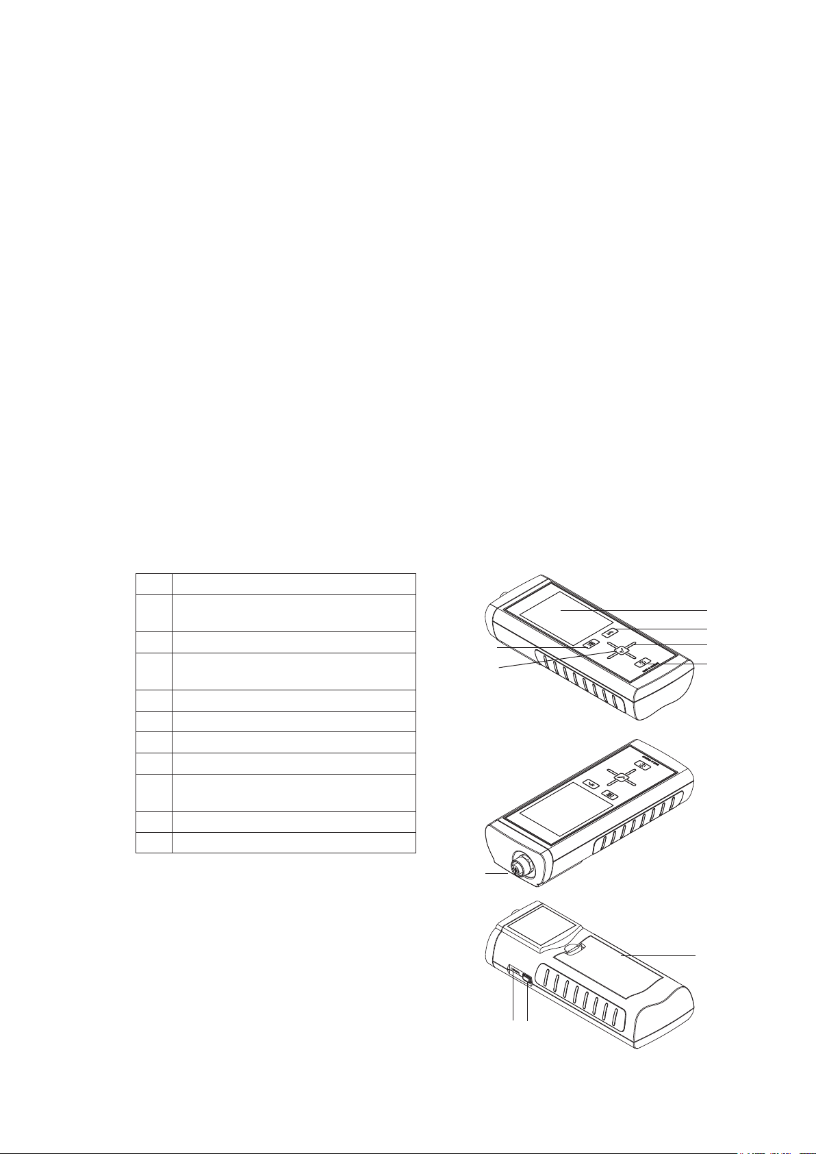
2.2 Device depiction
No. Operating element
scratch proof colour display with
1
touch function
2 "Back" key
cross control with "Up", "Down",
3
"Left", "Right" keys
4 "Illumination on/off" key
5 "OK" key
6 "Main menu" key
7 connection for digital sensors (5-pin)
battery compartment with battery
8
cover
9 "On/Off" key
10 micro USB connection
1
2
6
5
7
3
4
8
9
10
5
Page 6

2.3 Technical Data
General
Power supply 4 x Alkaline LR6 AA batteries, 1.5 V
(not in the scope of supply)
Optional power supply 5V DC via USB (cable included)
Temperature range operating: handheld and handle of sensing probe: 0...50°C
Internal memory for approx. 2 million measured values
Housing / protection class ABS / IP40
Dimensions (HxWxD) 170 x 62 x 34 mm
Weight ca. 205g (0.45 lbs)
Display TFT display, 54 x 41 mm (2.13 x 1.61”), illuminated
CE compatibility Hand-held: EN61000-6-2:2005 EN61000-6-3:2007
Logprobe: EN61326-1:2013 EN61326-2-3:2013
storage: -20...60°C (-4...140°F)
(6.69 x 2.44 x 1.34”)
Integrated air pressure sensor
Measuring range 800 to 1100 mbar (complete accuracy)
Accuracy max. ± 0.5 mbar (at 25 °C, 1013.25 mbar)
Long term stability typ. -1 mbar/year
2.4 Scope of supply
Scope of delivery includes:
• 1 x Multifunctional Hand-held
• 1 x USB connection cable
• 1 x Getting started guide
• 1 x Factory test certificate
(32...122°F)
• 1 x moisture in oil probe with calibration certificate*
• 1 x carrying case*
• 1 x operating manual*
• 1 x calibration device, salt solutions and calibration certificate**
Additionally available free of charge is the SmartGraph3 PC software (www.epluse.com/
smartgraph3) for archiving and analysing data.
3. SAFETY
Carefully read the operating manual before using the device and keep it within reach!
• Do not use the device in atmospheres containing sulphur, chlorine or salt.
• Ensure that all connection cables are protected from damage
(e.g. from kinks or crushing).
• Protect the device from permanent direct sunlight.
• Observe the storage and operating conditions (see chapter "Technical data").
3.1 Intended use
Use the multifunctional hand-held Omniport 30 only in the field of climate diagnostics, while
adhering to and following the technical data. To use the device for its intended use, only connect and use accessories and spare parts which have been approved by E+E Elektronik.
Intended use encapsulates e.g.
• the analyses of
• the utilization as reference device according to DIN EN ISO 9001.
– supply and exhaust air flows,
– fluctuations in relative humidity,
– condensate formation,
– heat build-ups and temperature fluctuations,
– moisture in oil measurement and
*) only for OILPORT SET
**) only for OILPORT SET with option C01
6
Page 7

3.2 Improper use
Do not use the device in potentially explosive atmospheres, or for measurements in liquids
(except oil). E+E Elektronik accepts no liability for damage resulting from improper use. In such
a case, entitlements to a warranty are forfeited. Any unauthorised modifications, alterations or
structural changes to the device are forbidden.
3.3 Personnel qualifications
People who use this device must:
• know and understand the dangers of working near live parts.
• take measures to protect themselves from direct contact with live parts.
• have read and understood the operating manual, especially the "Safety" chapter.
For maintenance or repair work which requires the housing to be opened, contact E+E
customer service. Devices which have been opened unlawfully are void of any warranty
and warranty claims
3.4 Residual risks
Hazardous electric current!
Work on the electrical components must only be carried out by an authorised specialist
company.
Hazardous electric current!
Never measure live parts.
Danger!
Do not leave the packaging lying around. Children may use it as a dangerous toy.
Danger!
Dangers can occur at the device when it is used by untrained people in an unprofessional or
improper way. Observe the personnel qualifications.
Caution!
To prevent damage to the device, do not expose it to extreme temperatures, extreme humidity
or moisture.
Caution!
To prevent damage to the device or to a connected probe due to overheating, observe the permissible operating and measuring ranges of the device and the connected probe. The
corresponding specifications are provided in the general catalogue for industrial measuring
devices or on www.epluse.com under the "Information material – Industrial measuring devices"
menu.
7
Page 8
4. TRANSPORT AND STORAGE
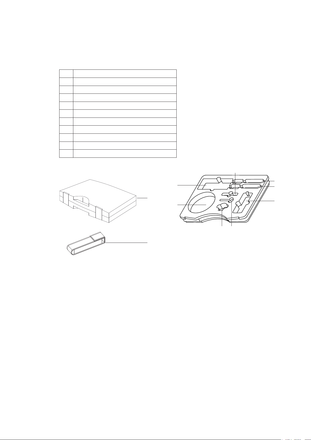
4.1 Transport
To safely transport the multifunctional hand-held and accessories, use the recommended carrying case (11). The carrying case is equipped with special compartments where the multifunctional hand-held and accessories can be kept. Otherwise, protect the device during use and
transport with an optional protective cover (12).
No. Operating element
11 Carrying case
12 Protective cover
13 OMNIPORT 30
14 CO2 probe
15 Miniature humidity probe
16 Humidity or flow probe with handle
17 Humidity or flow probe with handle
18 Calibration device
19 2x calibration solution
20 Cables and accessories
14
19
11
20
1518
12
4.2 Storage
When the device is not being used, observe the following storage conditions:
• dry, protected from dust and direct sunlight,
• with a plastic cover to protect it from invasive dust, if necessary.
• The storage temperature is the same as the range given in the chapter "Technical
data".
• When storing the device for a long time, remove the batteries.
• To store the device, use the carrying case (see chapter "Transport") wherever possible.
16
17
13
8
Page 9
5. OPERATION
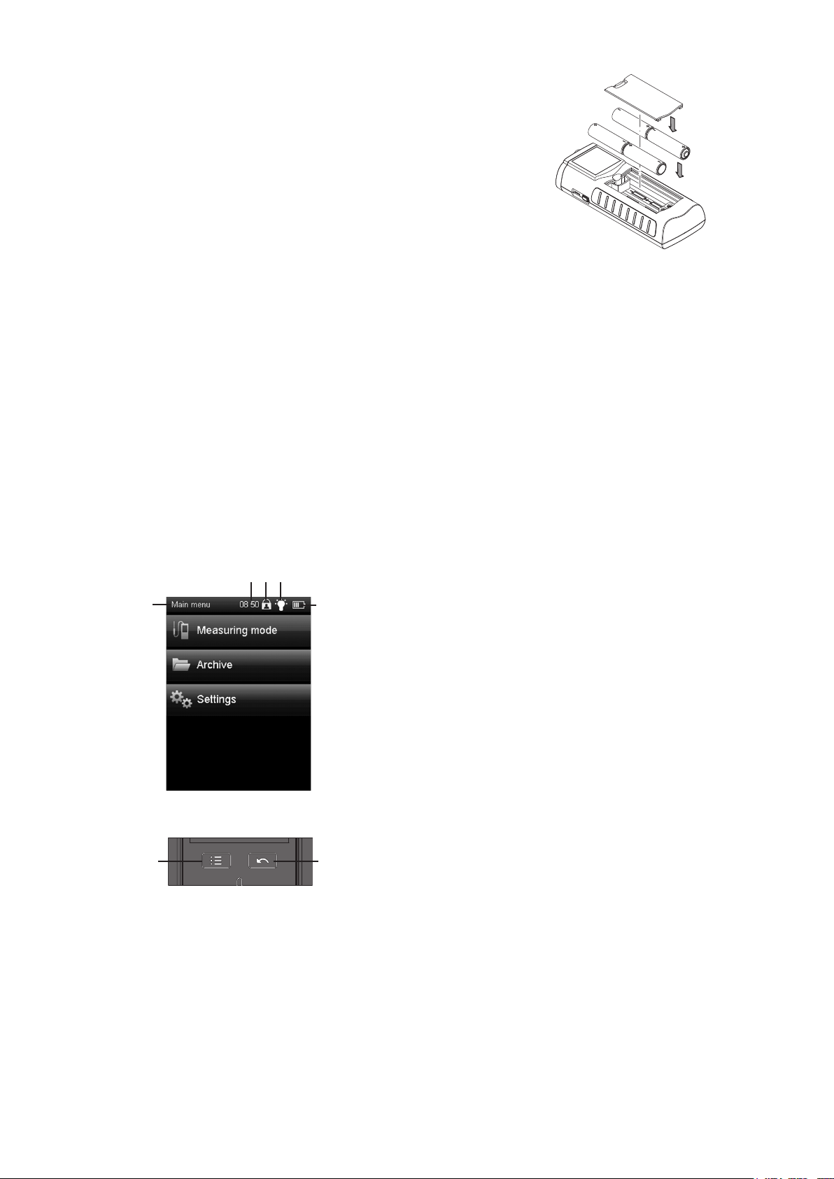
5.1 Inserting the batteries
4 x Alkaline LR6 AA batteries, 1.5 V (not in the scope of supply)
5.2 Switching on
1. Press and hold the "On/Off" key for approx.3 seconds until the device beeps.
2. Release the "On/Off" key – The colour display is switched on. The device is ready for
operation as soon as the screen of the particular measuring mode is displayed
(depends on the connected probe).
5.3 Switching off
1. Press and hold the "On/Off" key for approx. 3 seconds until the device beeps.
2. Release the "On/Off" key – The colour display is switched off.
5.4 Description of screen elements
When using the device, take special note of the following important operating elements and
displays:
• The "Back" key (2) opens the previous menu.
• The "Main menu" key (6) opens the main menu.
• Name of the current screen (21)
• Display of the current time (22)
• The "Padlock" symbol (23) appears when you press
and hold the "On/Off" key for approx. 1 second
during a measurement. The touch function of the
colour display is locked. To release the lock, press
and hold the "On/Off" key for approx. 1 second.
• The "Lightbulb" symbol (24) appears when you have
used the "Illumination on/off" key to switch on background illumination (see chapter "Information about
the device").
• Battery loading status indicator (25); a plug symbol is
shown when power is supplied via a USB connection.
All options which can be selected via touch function can also
be selected by using the cross control and the "OK" key. For
safety reasons, some options can only be selected and configured by using the cross control and the "OK" key (e.g. date
and time in the "Settings" screen).
21
22 2423
25
6
2
9
Page 10
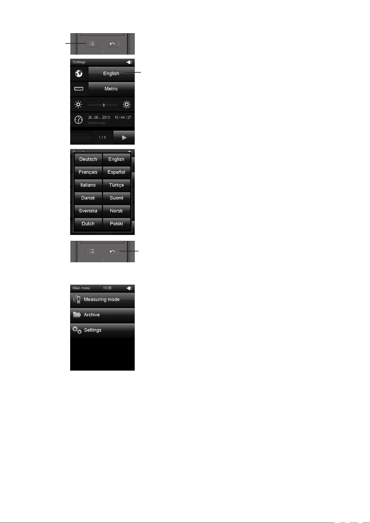
Set language
6
1. Press the "Main menu" key (6) to open the main menu.
2. Press the "Settings" key in the main menu.
26
3. Press the language selection key (26) in the "Settings"
screen.
4. Press the key with the desired language from the following
screen.– The selected screen language is activated
immediately.
5. Press the "Back" key (2) to return to the desired measuring
2
mode. Alternatively press the "Main menu" key and then the
"Measuring mode" key.
Main menu
You can open the following menus from the main menu:
Measuring mode:
Perform measurements in compliance with the connected
probe. If no probe is connected, only the values from the integrated air pressure probe are available.
Archive:
Open archived measured values
Settings:
Make any device settings
10
Page 11
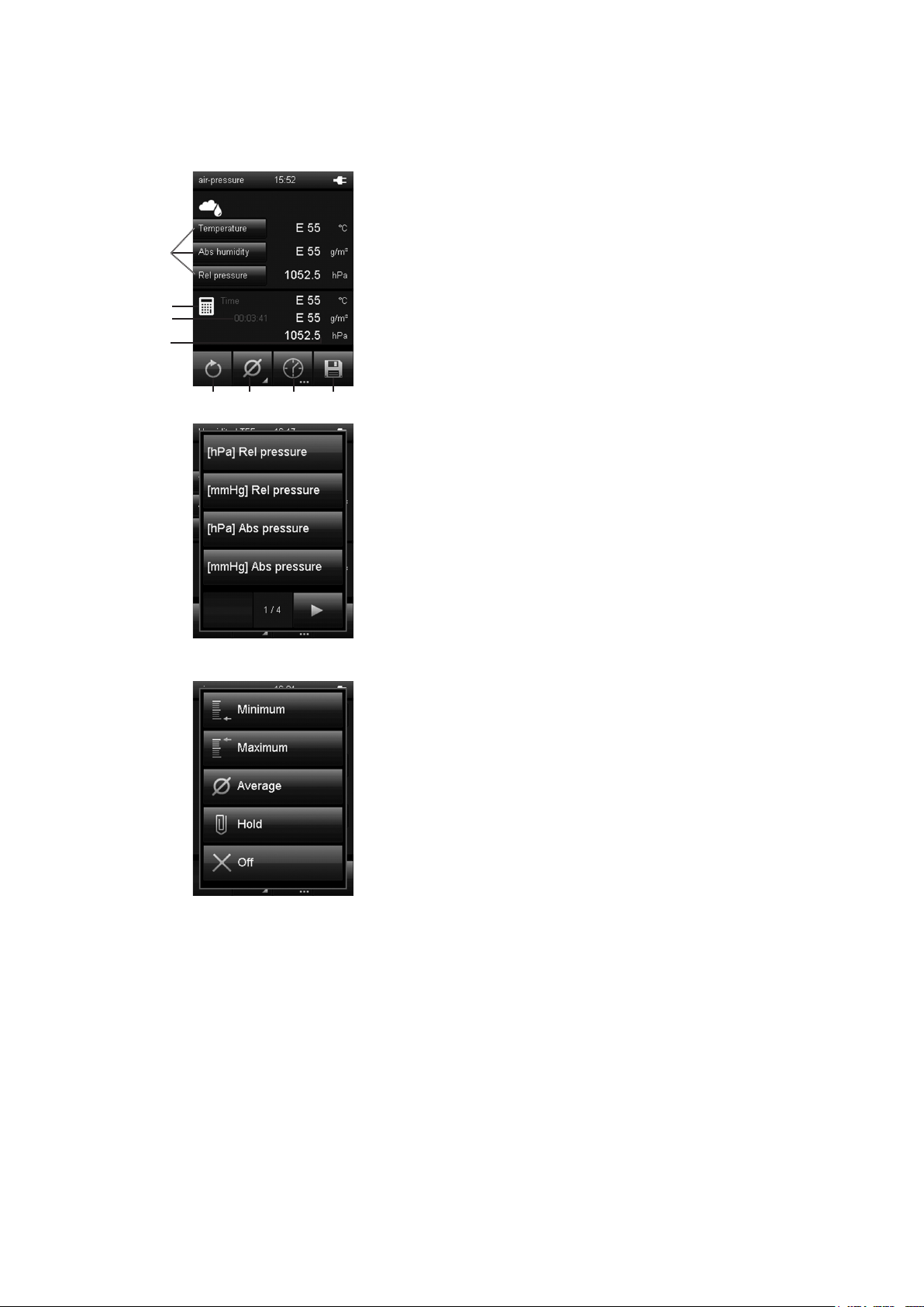
5.5 "Measuring mode – Air pressure" screen (integrated probe)
Note!
This measuring mode is only displayed when no digital probe is connected.
A.
1 When using the integrated air pressure sensor, only
select the measured values for air pressure (see fig. B.).
9
The latest measured value is displayed next to the corresponding key on the right (also see chapter "Explanation
1
2
3
4
B.
6 7 8
5
of the measured values", page 28).
The remaining selection options are disabled/greyed out.
Should you select one of the disabled entries, "E55" is
displayed. If applicable, deactivate the display by pressing
one of the keys marked (1) and selecting "Off" at the end
of the list in the pop-up window (see fig. B.).
2 This symbol indicates, that the displayed measured valu-
es under (4) are calculated (e.g. minimum/maximum measured value).
3 Indicates the measurement duration.
4 Displays the calculated measured values according to the
specifications under (1) and (6). The calculation starts
when switching the multifunctional hand-held on.
Actuating key (5) restarts the calculation of measured
values.
C.
5 Sets the measured values displayed under (4) and the
duration shown under (3) back to zero.
6 Specifies how the measured values under 4 are
shown (see fig. C.):
Minimum: Always shows the smallest detected
measured value from a measuring period.
Maximum: Always shows the largest detected
measured value from a measuring period.
Average: Shows the average value of all detected
measured values from a measuring period.
Hold: Pauses the current detected measured
value and shows it continually (when this
option is selected).
Off: Switches off the measured values (4).
7 Carries out an automatic measurement for the duration of
an already specified recording interval. The recording
interval can be specified in the following screen
(see fig. D. and fig. E., page 12).
8 Saves the currently displayed measured value as single
measurement in the archive with date and time stamp.
9 Opens the customer adjustment menu.
11
Page 12
5.6 "Measuring mode – Air pressure – Automatic measurement" screen
(integrated probe)
D.
10 hPa: Displays the measured value according to
the specifications under (1) (e.g. in the
measuring unit hectopascal)
(see fig. A., page 11).
11 Indicates the remaining recording duration for the auto-
E.
13 14 15
12
10
11
matic measurement.
12 Opens a screen for selecting the recording duration for
measuring over a long period (see fig. E.).
13 Starts recording. The key turns red once recording has
started.
Note!
During an active recording it is not possible to switch off
the multifunctional hand-held with the "On/Off" key.
Automatic switch-off is also deactivated. First stop the
recording by pressing key (13) and then turn off the
device.
14 Stops the current recording. The detected values are
automatically saved to the current measuring project.
15 Pauses the current recording.Key (12) flashes. Press key
(14) again to continue recording.
12
Page 13

5.7 "Customer Adjustment - Air pressure" screen
F.
G.
In measurement mode press button (1) in fig. F and select
one of the calculation modes shown in fig. C.
The CAL button will appear in the top right corner (only if
adjustement is possible for the selected measurand).
1
2
Adjustment is always performed for the
measurand in the top box !
In air pressure mode adjustement is only possible for measurands in hPa.
Press button CAL (2) in fig G. to open the customer adjustment mode.
H.
I.
For air pressure masurement a 1-point adjustment is
available
3
Select the value field (4) in fig. H to adjust the current measu-
4
red value (3).
Using the keypad in fig. I, enter the deviation of the current
measured value (3) from the reference value.
Press OK (5) to confirm and return to measurement mode.
Set the deviance to 0.00 to restore factory settings.
5
13
Page 14

5.8 "Measuring mode - Flow rate" screen
A.
1
2
3
4
5
6
B.
1 Shows the measured flow rate as a numerical value in
the selected unit (e.g. m/s).
In order to display and select the available units, touch
"Flow speed" (see chapter "Explanation of the measured
values", page 28).
2 Shows the measured flow rate as visual bars.
3 In order to display and select the available measured
values, touch "Temperature" (see chapter "Explanation of
the measured values", page 28).
Select "Off" to switch the display off.
4 Sets the measured values displayed under (6) and the
8
7
9 10
duration back to zero
5 This symbol indicates, that the displayed measured
values under (7) are calculated (e.g. minimum/maximum
measured value).
6 Displays the calculated measured values according to the
specifications under (1), (3) and (7):
Time: Duration of the interval
m/s: Shows the flow rate as a numerical value in the
selected unit (e.g. m/s).
°C: Displays the temperature value (e.g. in °C).
7 Specifies how the measured values under (6) are shown
(see fig. B.):
Minimum: Always shows the smallest detected
measured value from a measuring period.
Maximum: Always shows the largest detected
measured value from a measuring period.
Average: Shows the average value of all measured
values which have been detected so far
from a measuring period.
Hold: Pauses the current detected measured
value and shows it continually (when this
option is selected).
Off: Switches (6) display off.
8 Carries out an automatic measurement for the duration of
an already specified recording interval. The recording
interval can be specified in the following screen (see fig.
C. and fig. D., page 15).
9 Opens fig. E., page 16, where you can specify parame-
ters for the volumetric flow measurement (e.g. the form of
the object to be measured).
10 Saves the currently displayed measured value as single
measurement in the archive with date and time stamp.
14
Page 15

5.9 "Measuring mode – Flow rate – Automatic measurement" screen
11
12
13
14
C.
D.
15 16
17 18
11 Shows the measured flow rate as a numerical value in
the selected unit (e.g. m/s).
You can select the unit under (1) in fig. A., page 14.
12 Shows the measured flow rate as visual bars.
Note!
This display is only available when measuring flow values
The representations in fig. C. can slightly deviate depending on the previous setting.
13 Shows the measured temperature value.
14 Shows the remaining time until the automatic
measurement finishes.
15 Opens a screen for selecting the recording duration
(see fig. D.).
16 Starts recording.
The key turns red once recording has started.
Note!
During an active recording it is not possible to switch off
the multifunctional hand-held with the "On/Off" key. Auto
matic switch-off is also deactivated. First stop the recording by pressing key (17) and then turn off the device.
17 Stops the current recording. The detected values are auto-
matically saved to the current measuring project.
18 Pauses the current recording.Key (16) flashes.
Press the key (18) again to continue recording.
15
Page 16

5.10 "Measuring mode – Flowrate – Measuring range" screen
E.
19
20
21
22
F.
23
19 Selects the form of the object to be measured. The
following options are available (see fig. F.)::
1. Square (volumetric flow measurement)
2. Round (volumetric flow measurement)
3. Off (no volumetric flow measurement)
Depending on the selected form, a different equation is
used to calculate the measured values. The measured
values displayed under (1) or (3) in fig. A., page 14
depend on the settings selected here.
20 Determines the diameter of the object to be measured
(with selection "Round" under (19)).
21 Determines the height of the object to be measured (with
selection "Square" under (19)).
22 Determines the width of the object to be measured (with-
selection "Square" under (19)).
23 Saves the settings and returns to fig. A., page 14.
The measured values for the volumetric flow can only be
displayed under (1) in fig. A., page 14.
During volumetric flow measurement, further measured
values, such as the flow rate, can be displayed under (3)
in fig. A., page 14.
Note!
The settings saved here are also used for all following
measurements, unless they are deactivated (in the
corresponding menu item)
16
Page 17

5.11 "Customer Adjustment - Flowrate" screen
G.
1
2
H.
In measurement mode press button CAL (1) or (2) in order to
switch to customer adjustment mode (fig. G).
Button (1) opens flow speed adjustment (fig. H) and button
(2) opens temperature adjustment (fig. I).
Select the value field (4) in either fig. H or fig. I to adjust the
current measured value (3).
3
4
I.
3
4
J.
Using the keypad in fig. J, enter the deviation of the current
measured value (3) from the reference value.
Press OK (5) to confirm and return to measurement mode.
Set the deviance to 0.00 to restore factory settings.
5
17
Page 18

5.12 "Measuring mode – Humidity" screen
A.
1 Specifies how measured values and the corresponding
units are shown (see chapter "Explanation of the measu-
9
red values", page 28). The latest measured value is displayed next to the corresponding key on the right. Select
"Off" to switch the respective display off.
1
2 This symbol indicates, that the displayed measured values
under (4) are calculated (e.g. minimum/maximum measu-
2
3
4
red value).
3 Indicates the measurement duration.
4 Displays the measured values according to the specifica-
6 7 8
5
tions under (1) and (6):
°C: Displays the temperature according to the
specifications under (1) (e.g. in degrees Celsius)
and under (6) (e.g. as average value).
g/m3: Displays the humidity according to the
specifi- cations under (1) (e.g. in gram per cubic
metre) and under (6) (e.g. as average value).
hPa: Displays the air pressure according to the
B.
specifications under (1) (e.g. in the measuring unit
hectopascal) and under (6)
(e.g. as average value).
5 Sets the measured values shown under (4) back to zero.
6 Specifies how the measured values under (4) are shown
(see fig. B.):
Minimum: Always shows the smallest detected
measured value from a measuring period.
Maximum: Always shows the largest detected
measured value from a measuring period.
Average: Shows the average value of all detected
measured values from a measuring period.
Hold: Pauses the current detected measured
value and shows it continually (when this
option is selected).
Off: Switches off the measured values (4).
7 Carries out an automatic measurement for the duration of
an already specified recording interval. The recording
interval can be specified in the following screen
(see fig. C. and fig. D., page 19).
8 Saves the currently displayed measured value as single
measurement in the archive with date and time stamp.
9 Opens the customer adjustment screen.
18
Page 19

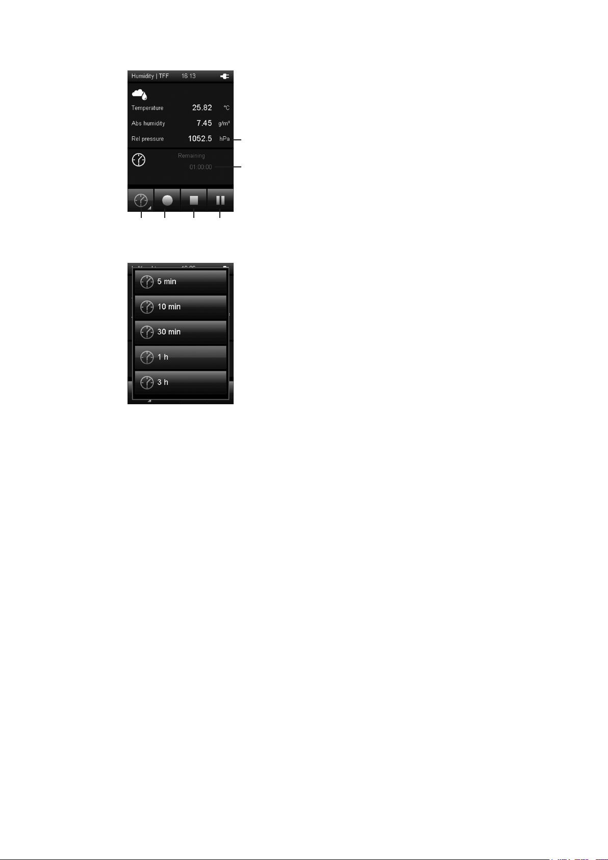
5.13 "Measuring mode – Humidity – Automatic measurement" screen
10
11
C.
D.
12
13
14
15
10 Displays the measured values according to the
specifications under (1) in fig. A.:
°C: Displays the temperature according to the
specifications under (1) (e.g. in degrees Cel-sius)
g/m3: Displays the humidity according to the
specifications under (1) (e.g. in gram per cubic
metre).
hPa: Displays the air pressure according to the
specifications under (1) (e.g. in the measuring
unit hectopascal)
11 Indicates the remaining recording duration for the
automatic measurement.
12 Opens a screen for selecting the recording duration for
measuring over a long period (see fig. D.).
13 Starts recording.
The key turns red once recording has started.
Note!
During an active recording it is not possible to switch off
the multifunctional hand-held with the "On/Off" key.
Automatic switch-off is also deactivated. First stop the
recording by pressing key (14) and then turn off the
device.
14 Stops the current recording. The detected values are
automatically saved to the current measuring project.
15 Pauses the current recording.Key (13) flashes.
Press key (15) again to continue recording.
19
Page 20

5.14 "Customer adjustment - Humidity" screen
E.
F.
In measurement mode press button (1) in fig. E and select
one of the calculation modes shown in fig. B.
The CAL button will appear in the top right corner (only if
adjustment is possible for the selected measurand).
1
2
Adjustment is always performed for the
measurand in the top box !
For rH/T probes an adjustment of humidity and temperature
is possible.
Press button CAL (2) in fig F. to open the customer adjustment mode.
G.
H.
Customer adjustment of RH/T probes:
3
4
Temperature
1-point offset or offset/gain adjustment according to probe
type.
Relative Humidity
1-point adjustment : (see fig. J on page 24)
CAL - the reference value must be in the range 40...60 %
RH.
2-point adjustment: (see fig. K on page 24).
CAL L - the reference value low must be in the range
0...40% RH.
CAL H - the reference value high must be in the range
60...95% RH.
Offset/Gain adjustment:
Set the linear offset and/or gain of the sensor curve.
Using the keypad in fig. H, enter the deviation of the current
measured value (3) from the reference value.
Press OK (5) to confirm and return to measurement mode.
Set the deviance to 0.00 to restore factory settings.
5
20
Page 21

5.15 "Measuring mode – Moisture in oil" screen
A.
15
1
2
3
4
B.
6 7 8
5
1 Specifies how measured values and the corresponding
units are shown (see chapter "Explanation of the measured values", page 28). The latest measured value is dis-
28
played next to the corresponding key on the right. Select
"Off" to switch the respective display off.
2 This symbol indicates, that the displayed measured values
under (4) are calculated (e.g. minimum/maximum measured value).
3 Indicates the measurement duration.
4 Displays the measured values according to the specifica-
tions under (1) and (6):
aw: Displays the water activity according to the
specifications under (1) (unitless) and under
(6) (e.g. as average value).
ppm: Displays the water content according to the
specifications under (1) (in ppm)
and under (6) (e.g. as average value).
5 Sets the measured values shown under (4) back to zero.
6 Specifies how the measured values under (4) are shown
(see fig. B.):
Minimum: Always shows the smallest detected
measured value from a measuring period.
Maximum: Always shows the largest detected
measured value from a measuring period.
Average: Shows the average value of all detected
measured values from a measuring period.
Hold: Pauses the current detected measured
value and shows it continually (when this
option is selected).
Off: Switches off the measured values (4).
7 Carries out an automatic measurement for the duration of
an already specified recording interval. The recording
interval can be specified in the following screen (see fig.
C. and fig. D., page 22).
8 Saves the currently displayed measured value as single
measurement in the archive with date and time stamp.
21
Page 22

5.16 "Measuring mode – Moisture in oil – Automatic measurement"
C.
9 Displays the measured values according to the
specifications under (1) in fig. A.:
aw: Displays the water activity according to the
specifications under (1) (unitless).
ppm: Displays the water content according to the
specifications under (1) (in ppm).
9
10
D.
11
12
13
14
10 Indicates the remaining recording duration for the
automatic measurement.
11 Opens a screen for selecting the recording duration for
measuring over a long period (see fig. D.).
12 Starts recording.
The key turns red once recording has started.
Note!
During an active recording it is not possible to switch off
the multifunctional hand-held with the "On/Off" key.
Automatic switch-off is also deactivated. First stop the
recording by pressing key (13) and then turn off the
device.
13 Stops the current recording. The detected values are
automatically saved to the current measuring project.
14 Pauses the current recording.Key (12) flashes.
Press key (14) again to continue recording.
22
Page 23

5.17 "Oil parameters – Moisture in oil" screen
A.
15
E.
16
17
18
The measurand "water content [ppm]" is a calculated
value. For this calculation oil specific parameters (A und B)
28
are needed. The default factory parameter set is [01]
EEPARAM1 , which contains oil specific parameters for
mineral transfomer oil. The determination of other oil-specific parameters can be performed by E+E on request.
15 Opens a screen for oil parameter selection (see fig. E).
The navigation is partially possible only by using the control cross!
16 Oil parameter set - [01] EEPARAM1 is the default factory
setting.
17 Add new oil parameter ser (see fig. G)
18 List of saved oil parameter sets.
A maximum of 10 entries is possible.
19 Select a parameter set (see fig. F).
20 Sends and saves the selected parameter set (under 19) in
the measuring probe.
19
F.
20
21
22
23
G.
24
21 Edit parameter set (see fig. G).
22 Delete parameter set.
23 Cancel action.
24 Enter name for oil parameter set. Navigate via control
cross.
25 Enter A-Parameter (-1999.9...100.0)
26 Enter B-Parameter (0.00..20.00)
27 Confirm and save oil parameters.
28 Opens screen for customer adjustment of the moisture in
oil probe (see fig. H).
25
27
26
23
Page 24

5.18 "Customer adjustment – Moisture in oil" screen
H.
29
33
29 Current measured value reading.
Note!
The customer adjustment is always performed for the
30
31
32
measurand in the top box (see fig. A).
30 1-point adjustment: to enter deviation from reference value
select field CAL (30).
31 2-point adjustment: to enter deviation from reference value
low select field CAL L (31).
32 2-point adjustment: to enter deviation from reference value
high select field CAL H (32).
33 Save and exit.
Customer adjustment for:
Temperature:
1-point offset adjustment (see fig. I)
Water activity aw:
1-point adjustment: rotation around zero (see fig. J).
CAL - the reference value must be in the range
0.40...0.60 aw (29).
2-point adjustment: (see fig. K).
CAL L - the reference value low must be in the range
0...0.40 aw (29).
CAL H - the reference value high must be in the range
0.60...0.95 aw (29).
Water content ppm: no adjustment possible.
I.
K.
Set the deviance to 0.00 to restore factory settings.
J.
24
Page 25

5.19 "Measuring mode – CO2" screen
A.
1
2
3
4
B.
6 7 8
5
1 Specifies how measured values and the corresponding
units are shown (see chapter "Explanation of the measu-
9
red values", page 28). The latest measured value is displayed next to the corresponding key on the right. Select
"Off" to switch the respective display off.
2 This symbol indicates, that the displayed measured values
under (4) are calculated (e.g. minimum/maximum measured value).
3 Indicates the measurement duration.
4 Displays the measured values according to the specifica-
tions under (1) and (6):
ppm: Displays the temperature according to the
specifications under (1) (e.g. in parts per million)
and under (6) (e.g. as average value).
5 Sets the measured values shown under (4) back to zero.
6 Specifies how the measured values under (4) are shown
(see fig. B.):
Minimum: Always shows the smallest detected
measured value from a measuring period.
Maximum: Always shows the largest detected
measured value from a measuring period.
Average: Shows the average value of all detected
measured values from a measuring period
Hold: Pauses the current detected measured
value and shows it continually (when this
option is selected).
Off: Switches off the measured values (4).
7 Carries out an automatic measurement for the duration of
an already specified recording interval. The recording
interval can be specified in the following screen
(see fig. C. and fig. D.).
8 Saves the currently displayed measured value as single
measurement in the archive with date and time stamp.
9 Opens the customer adjustment screen.
25
Page 26

5.20 "Measuring mode – CO2 – Automatic measurement" screen
10
11
C.
D.
12
13
14
15
10 Displays the measured values according to the
specifications under (1) in fig. A.:
ppm: Displays the CO
concentration according to the
2
specifications under (1) (e.g. in parts per million).
11 Indicates the remaining recording duration for the
automatic measurement.
12 Opens a screen for selecting the recording duration for
measuring over a long period (see fig. D.).
13 Starts recording.
The key turns red once recording has started.
Note!
During an active recording it is not possible to switch off
the multifunctional hand-held with the "On/Off" key.
Automatic switch-off is also deactivated. First stop the
recording by pressing key (14) and then turn off the
device.
14 Stops the current recording. The detected values are
automatically saved to the current measuring project.
15 Pauses the current recording. Key (13) flashes.
Press key (13) again to continue recording.
26
Page 27

5.21 "Customer Adjustment - CO2" screen
E.
F.
In measurement mode press button (1) in fig. E and select
one of the calculation modes shown in fig. B.
The CAL button will appear in the top right corner (only if
adjustement is possible for the selected measurand).
1
2
Adjustment is always performed for the
measurand in the top box !
CO
In
mode adjustement is only possible for the measurand
2
"CO2 momentary". The averaged value cannot be adjusted.
Press button CAL (2) in fig. F to open the customer adjustment mode.
G.
H.
For CO2 probes an offest / gain adjustment is possible.
3
Select the value field (4) or (5) in fig. G to adjust the current
measured value (3).
4
5
Using the keypad in fig. H, enter the offest (4) and gain(5)
deviations.
Press OK (6) to confirm and return to measurement mode.
Set the deviance to 0.00 to restore factory settings.
6
27
Page 28

5.22 Explanation of the measured values
Depending on the measuring mode and used probe, the following measured values can be
selected to be displayed in the corresponding measurement units:
[Unit] Measured value Meaning
3
[g/m
3
[gr/ft
[hPa]
[mmHg]
[psi]
]
]
Absolute
humidity
Absolute
pressure
Indicates the mass of water vapour in relation to the volume, in which
the humid gas is contained, in:
• grams per cubic metre
• grains per cubic foot
Indicates the barometric air pressure. This is the currently present pressure, based on an absolute vacuum of "0" and thus termed absolute
pressure. Possible units are:
• hectopascal
• millimetres of mercury
• pounds per square inch
[°C]
Ice bulb
3
]
3
]
temperature
Wet bulb
temperature
Frostpoint
temperature
Air density
[°F]
[°C]
[°F]
[°C]
[°F]
[kg/m
[lb/ft
[g/kg]
[gr/lb]
Saturation
ratio
[ppm]
[g/kg]
[gr/lb]
Mixing ratio
[ppm]
[g/kg]
[gr/lb]
Mass fraction
water vapour
[ppm]
3
/h]
[ft
3
/min]
[ft
3
/s]
[ft
3
/h]
[in
3
/min]
[in
[in
3
/s]
Norm volumetric
flow
[l/min]
3
/h]
[m
3
/min]
[m
3
[m
/s]
[hPa]
[psi]
Partial vapour
pressure
[%] Relative humidity
Indicates the temperature setting in at the interface of an icy surface
and a gas gushing past in:
• degrees Celsius
• degrees Fahrenheit
Indicates the temperature setting in at the interface of a wet surface and
a gas gushing past in:
• degrees Celsius
• degrees Fahrenheit
Indicates the temperature setting in dur- ing icing when the current partial water vapour pressure equals the saturated vapour pressure in:
• degrees Celsius
• degrees Fahrenheit
Indicates the mass of air in proportion to a certain volume in:
• kilograms per cubic metre
• pounds per cubic foot
Indicates the relative mass ratio of ambient air saturated with humidity
in the total mass in:
• grams per kilogram
• grains per pound
• parts per million
Indicates the mass of water vapour in proportion to the mass of dry gas
in:
• grams per kilogram
• grains per pound
• parts per million
Indicates the mass of water vapour in proportion to the mass of humid
gas in:
• grams per kilogram
• grains per pound
• parts per million
Converts the measured volumetric flow employing the ideal gas law to
standard conditions (temperature and pressure). The following standard
conditions can be set:
• DIN 1343: 0 °C/1013,25 mbar
• DIN ISO 2533: 25 °C/1013,25 mbar
• DIN 1945-1: 20 °C/1013,25 mbar
The following units can be selected:
• cubic feet per hour
• cubic feet per minute
• cubic feet per second
• cubic inches per hour
• cubic inches per minute
• cubic inches per second
• litres per minute
• cubic metres per hour
• cubic metres per minute
• cubic metres per second
Indicates the partial pressure of water in its gaseous phase in a given
volume of a gas or gas mixture in:
• hectopascal
• pounds per square inch
Indicates the relative humidity as the ratio of the partial water vapour
pressure to the saturated vapour pressure under saturation conditions
above water in per cent.
28
Page 29

[Unit] Measured value Meaning
[%]
[hPa]
Relative humidity
technical
Indicates the relative humidity as the ratio of the partial water vapour
pressure to the saturated vapour pressure under satura- tion conditions
above ice in per cent (only with temperatures below 0 °C).
Indicates the air pressure corrected to sea level employing the international baro- metric height formula in:
• hectopascal
[mmHg]
Relative
pressure
• millimetres of mercury
• pounds per square inch
[psi]
[hPa]
[psi]
[hPa]
[psi]
Saturation water vapour
pressure above ice
Saturation water vapourpressure above water
[kJ/kg]
Specific
enthalpy
[BTU/lb]
[m/s]
Flow speed
[fpm]
[°C]
Dew point-
[°F]
temperature
[°C]
Temperature
Volume fraction of
water vapour
Flow rate
[ppm]
[ft
3
[ft
[ft
[in
[in
[in
[°F]
[%]
3
/h]
/min]
3
/s]
3
/h]
3
/min]
3
/s]
[l/min]
3
[m
/h]
3
[m
/min]
3
[m
/s]
[aw] Water activity (oil)
[ppm] Water content (oil)
CO
-concentration
[ppm]
[ppm]
2
momentary
CO
-concentration
2
averaged
The conversion enables that air pressures can be compared with one
another inde- pendent of the sea level.
Indicates the partial water vapour pres- sure under saturation conditions
above ice in:
• hectopascal
• pounds per square inch
Indicates the partial water vapour pres- sure under saturation conditions
above water in:
• hectopascal
• pounds per square inch
Indicates the state variable of the humid gas, which is composed of the
specific enthalpies of the mixture components and based on the mass
fraction of the dry gas, in:
• British Thermal Unit per pound
• Kilojoule per kilogram
Indicates the movement of fluids or gases as proportion of length to a
certain time in:
• feet per minute
• metres per second
Indicates the temperature setting in during condensation when the current partial water vapour pressure equals the saturated vapour pressure
in:
• degrees Celsius
• degrees Fahrenheit
Indicates the measured air temperature in:
• degrees Celsius
• degrees Fahrenheit
Indicates the volume fraction of water vapour in proportion to the total
volume of humid gas in:
• per cent
• parts per million
Indicates the volume calculated from the measured flow rate and the set
area in:
• cubic feet per hour
• cubic feet per minute
• cubic feet per second
• cubic inches per hour
• cubic inches per minute
• cubic inches per second
• litres per minute
• cubic metres per hour
• cubic metres per minute
• cubic metres per second
Analogous to gas humidity, water activity of an oil is a ratio of the actual
water content to the water content at saturation point.
Displays the ratio of mass water to mass oil. Water content is a value
calculated from water activity and oil temperature. Oil specific parameters are needed for the calculation.
Displays the current CO2 concentration in air. The measured value is
updated every 15 seconds..
Displays the CO2 concentration in air. The measured value is the median of the last 11 measured values.
29
Page 30

5.23 "Archive" screen
In the "Archive" screen, you can view archived measuring projects or open them for further
processing:
Archive, fig. A.:
1
2 3
1 Shows the measuring projects which are saved in the
archive.The currently selected archive entry is highlighted
1. Press the "Down" key on the cross control until the
desired archive entry is selected.
2. You may need to turn the page by pressing the "Left"or
"Right" keys on the cross control.
3. Press the "OK" key on the cross control to confirm the
selected archive entry. You can also press "OK" (2) on
the screen key. Fig. B. opens.
2 Selects the currently selected archive entry.
Fig. B. opens.
3 Deletes all entries from the archive.
A safety prompt opens. Confirm it by pressing the
"OK" key if you want to delete all entries. Otherwise,
touch the "Cancel" key
The icons beside the saved measuring projects show each
measuring mode (see examples in fig.A.).
The meaning is as follows:
Archive, fig. B.:
4
5
6
Flowrate measurement
Measurement of humidity, temperature or air pressure
Spot measurement
Time measurement
4 Opens the selected archive entry (see fig. C.).
5 Deletes the selected archive entry. A safety prompt
opens.Confirm it by pressing the "OK" key if you want to
delete the entry. Otherwise, touch the "Cancel" key.
6 Closes fig. B. and returns to fig. A.
30
Page 31

Archive, fig. C.:
7
8
5.24 "Settings" screen
7 Charts (top of fig. C.) and tabulates (bottom of fig. C.) the
measured values.
You can select one of the three different measurement
channels using the "Up" and "Down" keys on the cross
control until. The selected measurement channel will be
highlighted in the table.
Displayed in the table are the minimum value (MIN), the
maximum value (MAX), the arithmetic average (Ø) and
the standard deviation (SD).
In case the data won't fit onto one table page after a
longer recording session, you can browse through the
timeline ([s], on the right in fig. C.) by using the "Left"
and "Right" keys on the cross control unit.
8 Closes the selected archive entry and returns to fig. A.
Settings 1/3:
1
2
3
4
You can configure the device as follows in the "Settings"
screen:
1 Selects the screen language (see chapter "Set language").
2 Selects the unit system:
Metric: Activates the metric unit system for all available
measured values (e.g. for use in
continental Europe).
Imperial: Activates the imperial unit system for all
available measured values (e.g. for use in
the USA).
3 Sets the screen brightness. This option can only be selec-
5
ted by using the cross control below the colour display.
1. Press the "Down" key on the cross control until the
scale is selected.
2. Press the "Left" or "Right" keys on the cross control to
reduce (left) or increase (right) the screen brightness.
4 Sets the date and time.
This option can only be selected by using the cross control
below the colour display.
1. Press the "Down" key on the cross control until the
date is selected.
2. Press the "OK" key on the cross control.
The entire row is selected
3. Press the "Left" or "Right" keys on the cross control to
select the value to be configured.
4. Press the "Up" or "Down" keys on the cross control to
increase or reduce the value to be configured.
31
Page 32

Settings 2/3:
6
7
8
9
Settings 3/3:
11
10
5. Press the "OK" key on the cross control.
The row is deselected.
5 Opens the next screen.
6 Either specifies the period for automatic dimming of the
colour display or deactivates the function:
30 seconds, 1 minute, 5 minutes, off
7 Either specifies the period for automatic switch-off of the
colour display or deactivates the function:
10 minutes, 30 minutes, 1 hour, off
Note!
This function is deactivated during an automatic measurement.
8 Switches signal tones/key tones on or off.
9 Sets the height above sea level (SL).
This value is i.a. required for the calculation of the relative
air pressure and other values.
This option can only be selected by using the cross control
below the colour display.
1. Press the "Down" key on the cross control until the
numerical value is selected.
2. Press the "OK" key on the cross control.
The first number is selected.
3. Press the "Left" or "Right" keys on the cross control to
select the number to be configured.
4. Press the "Up" or "Down" keys on the cross control to
increase or reduce the value to be configured.
5. Press the "OK" key on the cross control.
The single number is deselected.
10 Opens the next screen.
11 Determines the setting for the amount of gas or the
volumetric flow to be measured (also see chapter
"Explanation of the measured values" page 28):
DIN 1343, DIN ISO 2533, DIN 1945-1
Note!
Before using the multifunctional hand-held, make sure that
you are aware of the device's intended purpose and the
respective standard in effect as well as the contents of this
standard.
32
Page 33

5.25 Performing measurement (exemplary using probe for temperature
and air flow measuring)
Note:
Note that moving from a cold area to a warm area can lead to condensation forming on the
device's circuit board. This physical and unavoidable effect can falsify the measurement. In this
case, the colour display shows either no measured values or they are incorrect. Wait a few
minutes until the device has become adjusted to the changed conditions before carrying out a
measurement.
After connecting a probe, the multifunctional hand-held automatically selects the appropriate
measuring mode. The corresponding screen is displayed and the measurement begins.
flow direction
5.26 Shut down procedure
1. Switch off the device by pressing the "On/Off" key (see chapter "Switching off").
2. Detach connecting cables and sensors.
3. Clean the device according to the chapter "Maintenance".
4. Store the device according to the chapter "Storage".
33
Page 34

6. PC-SOFTWARE
Use the SmartGraph3 PC software to carry out a detailed analysis and visualisation of your
measured results. Only by employing this software can all options of the multifunctional handheld for visualization and functioning be utilized (e.g. data export into an Excel/PDF file or data
output in form of a printout).
You can open a basic display of your measured values at any time in the device (see chapter
"Description of screen elements").
6.1 Installation conditions
Ensure that the following minimum requirements for installing the SmartGraph3 PC software
are fulfilled:
• Supported operating systems (32 or 64 bit version):
– Windows XP from service pack 3
– Windows Vista
– Windows 7
– Windows 8
• Software requirements:
– Microsoft .NET Framework (is automatically installed during the software
installation, where applicable)
• Hardware requirements:
– Processor speed: 1.6 GHz, minimum
– USB connection
– 2 GB RAM, minimum
– 1 GB hard disk space, minimum
6.2 Installing the PC software
1. Download the current PC software from the Internet. To do so, visit the
website www.epluse.com/smartgraph3.
2. Double-click the downloaded file.
3. Follow the instructions of the installation wizard.
6.3 Starting the PC software
1. Start the SmartGraph3 software.
2. Switch on the multifunctional hand-held (see chapter "Switching on") if necessary.
3. Connect the multifunctional hand-held to your PC via the USB connection cable
provided in the scope of delivery. After a few seconds (up to one minute) the multifunctional
hand-held is automatically detected and added to the device list in the
SmartGraph3 software.
Information about using the PC software is provided in the online help.
34
Page 35

7. ERRORS AND FAULTS
The accurate functionality of the device was tested during production a number of times.
However, if functionality faults do occur, then check the device according to the following list.
The device does not switch on:
• Check the loading status of the batteries. Replace the batteries when the battery
symbol in the colour display only shows one bar. If the battery symbol is red, then the
battery voltage is insufficient.
• Check that the batteries are properly positioned. Check the polarity is correct.
• Never carry out an electrical check yourself
The device is switched on, but no measured values are displayed:
• Check whether the multifunctional hand-held is in the correct probe mode.
• Check the connected connection cable for correct fit.
• Check the used connection cable and its connections as well as the connections to the
multifunctional hand-held for damage (e.g. broken cable, damaged contacts etc.). Use
a different connection cable of the same type to rule out possible faults.
• Ensure that the appropriate probe for the measurement is being used. Here, also consider the general catalogue or the product catalogue for measuring devices.
• Ensure that the colour display is switched on. Possibly use the "Illumination on/off" key
(see chapter "Device depiction").
• Check the room temperature and the relative humidity. Check the device's permissible
operating range complies with the technical data.
• Check whether the multifunctional hand-held responds to touching of the colour display. If it shows no reaction despite an enabled colour display and sufficient battery
power, remove the batteries for approx. 1 minute. Subsequently refit the batteries (see
chapter "Inserting the batteries") and restart the multifunctional hand-held.
7.1 Status and error codes
Status/error code Meaning
E 27 Faulty factory setting
E 2C Failed initialization of a component
E 50 Measured value above the specified range
E 51 Measured value below the specified range
E 52 Measured value physically supersaturated(upper limit)
E 53 Measured value physically supersaturated (lower limit)
E 54 Receipt of invalid data
E 55 Probe missing or defective
E FF Unknown fault
8. MAINTENANCE
8.1 Maintenance and care intervals
Maintenance and
care interval
check connections for digital
sensors and micro USB for dirt
and foreign objects and clean
if necessary
clean housing X X
visually check whether the
device is dirty
replace batteries X
check for damage X
carry out a test run X
before
every start
X
when
necessary
X X
at least
every 4 weeks
at least
annually
35
Page 36

8.2 Activities for before the start of maintenance
1. Switch off the device (see chapter "Switching off").
2. Detach connecting cables and probes.
For maintenance or repair work which requires the housing to be opened, contact E+E
customer service. Devices which have been opened unlawfully are void of any warranty and
warranty claims.
8.3 Visual inspection of the device
1. Check the device for dirt and possible damage.
2. Check the connection for digital probes and the micro USB connection for dirt and
possible damage.
3. Check the colour display for dirt and possible damage.
4. Check that the batteries and battery cover sits properly.
Damaged connections can falsify measurements and measurement results.
A damaged colour display can influence how measured results are shown.
8.4 Cleaning the device
1. Use a soft, lint-free cloth for cleaning.
2. Dampen the cloth with clean water. Do not use sprays, solvents, alcohol-based or abrasive
cleaners to dampen the cloth.
3. Clear dirt from the housing, the connections and the colour display.
8.5 Maintenance of humidity probes
Instructions for proper cleaning and calibration of the humidity probes, can be found online at
www.epluse.com/omniport30 in the section "Downloads".
36
Page 37

9. DISPOSAL
In the European Union, electronic equipment must not be treated as domestic waste, but must
be disposed of professionally in accordance with directive 2002/96/EC of the European
Parliament and Council of 27th January 2003 concerning old electrical and electronic equipment. After the end of its use, please dispose of this device in a manner appropriate to the relevant legal requirements.
In the European Union, batteries must not be treated as domestic waste, but must be disposed
of professionally in accordance with Directive 2006/66/EC of the European Parliament and
Council of 6th September 2006 concerning batteries and accumulators. Please dispose of batteries in a manner appropriate to the relevant legal requirements.
10. DECLARATION OF CONFORMITY
in accordance with EC Low Voltage Directive 2006/95/EC and the EC Directive 2004/108/EC
about electromagnetic compatibility. Herewith, we declare that the multifunctional hand-held
Omniport 30 was developed, constructed and produced in compliance with the named EC
directives.
Applied harmonised standards:
EN 61326-1:2006,
EN 61326-2-1:2006
IEC 61326-1:2005
IEC 61326-2-1:2005
The marking is found on the rear of the device.
37
Page 38

38
Page 39

39
Page 40

HEAD OFFICE:
E+E ELEKTRONIK Ges.m.b.H.
Langwiesen 7
A-4209 Engerwitzdorf
Austria
Tel: +43 7235 605 0
Fax: +43 7235 605 8
info@epluse.com
www.epluse.com
SALES OFFICES:
E+E CHINA / BEIJING
Tel: +86 10 84992361
info@epluse.cn www.epluse.cn
E+E CHINA / SHANGHAI
Tel: +86 21 61176129
info@epluse.cn www.epluse.cn
E+E GERMANY
Tel: +49 6172 13881 0
info@epluse.de www.epluse.de
E+E FRANCE
Tel: +33 4 7472 35 82
info@epluse.fr www.epluse.fr
E+E ITALY
Tel: +39 02 2707 8636
info@epluse.it www.epluse.it
E+E KOREA
Tel: +82 31 732 6050
info@epluse.co.kr www.epluse.co.kr
E+E USA
Tel: +1 508 530 3068
office@epluse.com www.epluse.com
 Loading...