

Page 1

HUMOR 20 +
Automatic Calibration Module
HUMIDITY CALIBRATOR
BA_Humor20_e // v3.3 // technical data are subject to change // 302252
MANUAL
Hardware + Software
Page 2

Table of contents
1. FOREWORD 3
2. SCOPE OF SUPPLY 4
2.1 HUMOR 20 4
2.2 Automatic calibration module (optional) 4
3. SAFETY INSTRUCTIONS 5
3.1 General 5
3.2 HUMOR 20 5
4. OPERATING PRINCIPLE 6
5. OPERATING COMPONENTS 7
5.1 HUMOR 20 7
5.2 Automatic calibration module (optional) 7
6. GENERAL USER INSTRUCTIONS 7
6.1 Setup 7
6.2 Starting up HUMOR 20 8
6.3 Starting up HUMOR 20 with automatic calibration module 9
6.4 Verifying the 100%RH Point 11
7. CALIBRATION AND ADJUSTMENT PROCEDURE 12
7.1 Cubical transmitters (room design) with HUMOR 20 12
7.2 Transmitter with sensor probe with HUMOR 20 12
7.3 Transmitter EE33 Model J with HUMOR 20 13
7.4 Analogue Output HUMOR 20 14
7.5 Calibration with the automatic calibration module 14
7.6 Power failure during the calibration procedure 14
7.7 Ending the calibration or adjustment procedure 14
8. HUMOR 20 SOFTWARE 15
8.1 Installation the software 15
8.2 Configuration mode control panel 16
8.3 Menu bar 16
8.3.1 Operation 16
8.3.2 Adjustment / Calibration 22
8.3.3 Pressure Compensation 23
8.4 Measurements 24
8.4.1 Start screen 24
8.4.2 "Test unit" configuration field 24
8.4.3 "Measurements" configuration field 26
8.5 Fixed RH Value (only available when using an automatic calibration module) 27
9. MAINTENANCE 27
9.1 Re-fill water (at error message - waterlevel low) 27
9.2 Drain water (at error message - waterlevel high or long idle periods) 27
9.3 Cleaning 27
10. WARNINGS / ERROR MESSAGES ON THE DISPLAY 28
10.1 Humidity - display flashes 28
10.2 Warning: OUT OF SPEC 28
10.3 Warning: WATERLEVEL HIGH 28
10.4 Warning: WATERLEVEL LOW 29
10.5 Error message: heat defect 29
10.6 Error message: pressure excess 29
10.7 Humidity - display is incorrect 29
10.8 Stabilisation time too long 29
10.9 Leakage in filter set 30
10.10 Electronic defect - replace electronics 30
10.11 Fuse defect - Replacing the fuse (Humor20 + Autokit) 30
11. TECHNICAL DATA 31
12. ACCESSORIES 32
12.1 Oil-free compressor 32
12.2 Covers for measuring chamber 32
12.3 Calibration certificate 32
12.4 Automatic calibration module 32
2
Page 3

LIMITED LIABILITY
E+E Elektronik® shall not be held liable for any damage or consequential damage (for example, but
not restricted to, loss of earnings, interruption of business, loss of information and data or any other
financial losses) resulting from the setup, use or impossibility of use of an E+E Elektronik® software
product and any associated support services or non-performance of support services.
E+E Elektronik® Ges.m.b.H. is not responsible for the completeness of this publication and shall
not be liable for the products described herein in the event of improper handling.
This publication may contain technical inaccuracies or typographical errors. The information contained herein is revised regularly. These changes will be implemented in later editions. The products
described herein may be improved or changed at any time.
© Copyright E+E Elektronik GmbH // All rights reserved // Subject to change without notice
1. FOREWORD
E+E Elektronik® Ges.m.b.H. developed this device to accurately generate the relative
humidity (Uw).
As such, this professional tool represents the manufacturer's current status of knowledge with
regard to development, design and production. The manufacturer is confident that the humidity
calibrator HUMOR 20 meets all the requirements and expectations that you, the buyer, demand of
a new acquisition. If the device is handled properly and serviced regularly it should work reliably for
several years.
This manual forms part of the scope of supply and serves to ensure proper handling and optimal
performance of the device.
Therefore, make sure you read the manual before you take the device into operation. The manual
is also to be brought to the attention of any person involved in transport, setup, operation, maintenance or repair.
This manual must not be used for competitive purposes without our written consent and must not
be passed on to third parties. Copies for personal use are permitted.
All information, technical data and illustrations contained in this manual are based on the information available at the time of publication.
E+E Elektronik® Ges.m.b.H. reserves the right to change the technical data or make other technical
modifications at any time and without prior notice without being committed to retrofitting models
produced before such a change was made.
General
This manual is part of the scope of supply and serves to ensure the optimum operation and performance of the device.
To ensure correct operation, this manual must be read before the device is taken into operation.
Explanation of symbols
This symbol indicates a safety instruction.
These safety instructions must always be followed. The manufacturer is not liable for any damage
resulting from non-compliance. In this case, the user is solely responsible for his actions.
This symbol indicates a note.
These notes should be observed to achieve optimal performance of the equipment.
3
Page 4
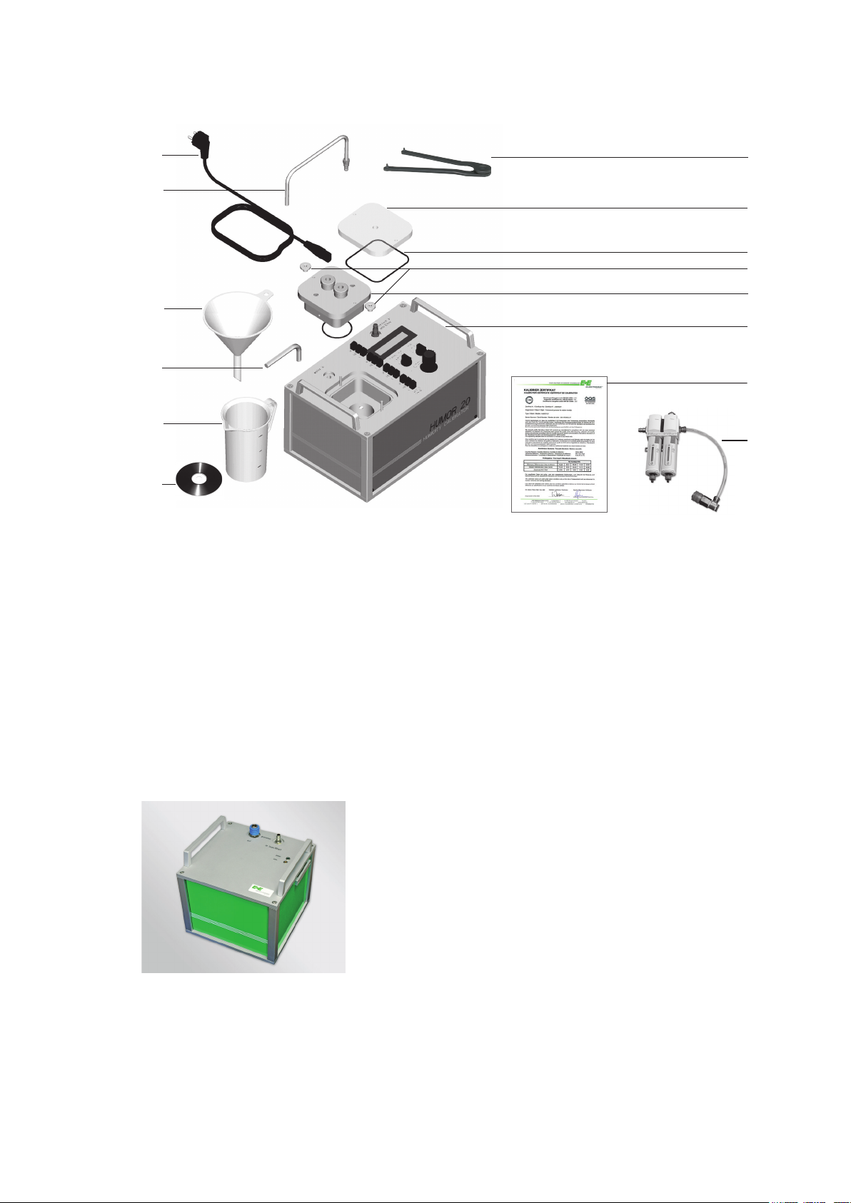
2. SCOPE OF SUPPLY
2.1 HUMOR 20
1
2
3
4
5
6
1 Power supply cable IEC Europe (230V) + power supply
cable IEC Northamerica (110V)
2 Water drain pipe with connector
3 Funnel
4 Allen key (10mm /
5 Measuring beaker
6 Measuring and calibration software
7 Face pin wrench
8 Plexiglas cover for room transmitter testing
0.4”)
7
8
9
10
11
12
13
14
9 O-ring for room transmitter
10 Knurled nut
11 Cover for measuring chamber (ordering
code HA0202xx) (not inlcuded in the
scope of supply HUMOR 20)
12 Fixing bracket for filter set
(pre-mounted)
13 Works certificate acc. DIN EN 10204-3.1
14 Filter set with oil separator
2.2 Automatic calibration module (optional)
• Automatic calibration module
• Power supply cable IEC Europe (230V)
• Power supply cable IEC North America (110V)
• RS232 connection cable to HUMOR 20
• Compressed-air connecting hose to HUMOR 20
4
Page 5

3. SAFETY INSTRUCTIONS
3.1 General
HUMOR 20 is designed based on state-of-the-art technology, which means it will operate reliably if
it is kept in good condition and operated and serviced correctly. This device may pose a risk if it is
operated improperly by untrained personnel.
Improper use can:
• Injure operating personnel and damage the device itself or other assets belonging to the user.
• Prevent the device from working efficiently and accurately.
Observe the following information to ensure operational safety:
• Only qualified or specially trained staff may operate or perform work on the humidity
calibrator.
Unauthorised changes or modifications are either not permitted or require the express
permission of the manufacturer.
• Read this manual carefully before taking the device into operation. The manual must
also be made available to any person involved in transport, setup, operation, maintenance or repair (particularly when loaning or selling the device to a third party).
• Only operate the device if it is in good condition. Any fault must be repaired by authorised personnel or by an E+E Elektronik sales partner before it is taken into operation
again.
3.2 HUMOR 20
• Check whether the supply voltage data on the nameplate matches the local supply
voltage. This also applies to the automatic calibration module.
• Only power the humidity calibrator via a grounded power outlet (safety precaution).
This also applies to the automatic calibration module.
• HUMOR20 and automatic calibration module should be placed in a way which allows
an as easy as possible disconnection from the power supply.
• Before opening the water intake, make sure that the humidity calibrator is no longer
under pressure (controller turned to the left as far as it will go; if HUMOR 20 already in
service, display shows RH > 90%).
• HUMOR 20 may only be operated with distilled (deionised) water.
• Before connecting the compressed air or nitrogen supply, make sure that the controller
is turned to the left as far as it will go.
• The device may only be operated with filtered compressed air with a contamination
level of <0.01mg/m³.
• The media supply may not exceed an absolute pressure of 10 bar (pressure gauge
and safety value recommended for use in the supply line).
• If a humidity calibrator is filled with water and ready for operation, it must not be
tilted by more than 20° during transportation. If this is not possible, HUMOR 20
must be drained completely, see section "9.2 Drain water".
• Once HUMOR 20 has been switched off, it must also be disconnected from the
compressed air (because of possible condensation in the lines as the heating is
turned off).
5
Page 6
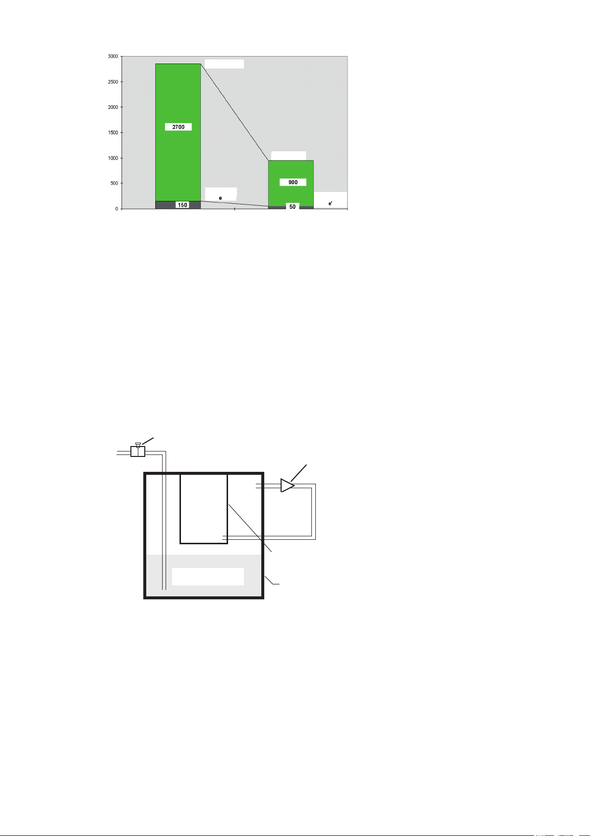
4. OPERATING PRINCIPLE
Dry air
Air or nitrogen under pressure p1 is
fed into chamber 1 and humidified.
The developing saturation vapour
pressure ews is a direct result of the
temperature of the chamber respectively the water. Next, the humidified
air is expanded to pressure p and
Pressure [mbar]
Dry air
fed into chamber 2. During expansion, the vapour pressure ews is
reduced in the same ratio as the
overall pressure of the air. Therefore,
Vapour pressure
Vapour pressure
the water vapour pressure in
chamber 2 is:
e = ews * p/p1
Thanks to the special design of HUMOR 20 with its high thermal conductivity, chamber 1 always
has the same temperature as chamber 2.
Consequently, if the temperature is the same, the saturation vapour pressure ews of chamber 1 is
identical to that of chamber 2. As a result of the expansion of the humidified air, chamber 2 contains
the water vapour partial pressure e.
From the definition for relative humidity follows for chamber 2:
rh = e/ews = ews * (p/p1) / ews = p/p1
Hence, the relative humidity in chamber 2 is a direct result of the ratio of the pressures in chambers
1 and 2.
Air
p
Pressure regulator
1
Reducing valve
In addition, the relative humidity
generated in HUMOR 20 is practically independent of the ambient
temperature and only dependent
p , T
e
e
ws
p1 --> p
on the pressures p and p1. The
only precondition is that the temperature of chambers 1 and 2 and
the water
in chamber 1 is the same.
Measuring chamber
The relative humidity in chamber 2
can be varied by adjusting the inlet
Water T, p
1
Saturation chamber
pressure p1. During operation, the
pressures in chambers 1 and 2 are
measured and the actual relative
humidity is calculated with the
Schematic diagram of a two-pressure reactor
above equation and shown in the
display of the calibrator.
6
Page 7
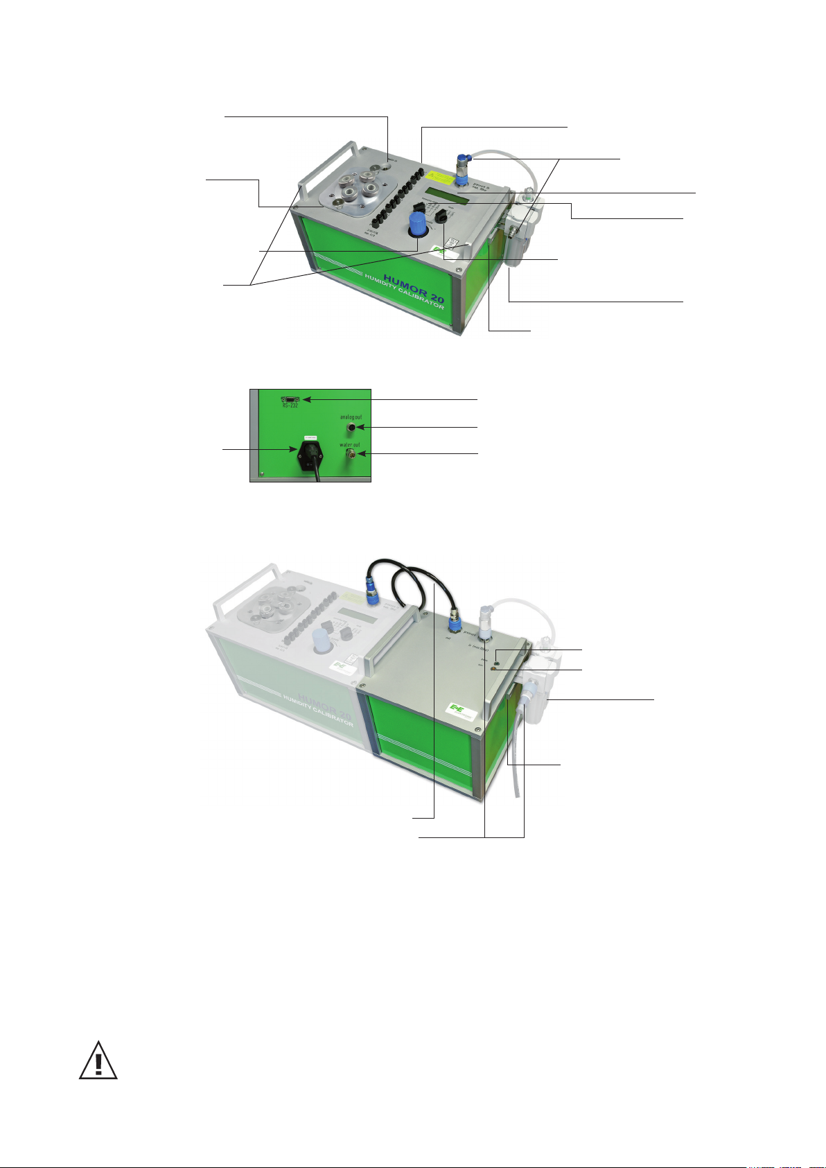
5. OPERATING COMPONENTS
5.1 HUMOR 20
Water intake
Measuring
chamber
Humidity controller
Carry handle
HUMOR 20 - Back Side
power cable
+ switch
+ fuse
Supply voltage + measuring
inputs for test units
Pressure supply
(compressed air / N2)
output signal test unit
Switch 2: for test unit 1-4 and
measuring chamber temperature
Bracket for filter set
serial interface
socket "analogue output HUMOR 20"
water out
(pre-mounted)
Display
Switch 1:
Filter set
5.2 Automatic calibration module (optional)
Compressed-air connecting hose
Pressure supply (compressed air / N2)
(*) Lights up when power is supplied
(**) - Flashes: Adjusted to setpoint
- Lights up: Setpoint reached
6. GENERAL USER INSTRUCTIONS
Green "power" LED (*)
Orange "auto" LED (**)
filter set
Bracket for filter set
(pre-mounted)
6.1 Setup
Operating range: 10...40°C / 10...80% rH.
Do not perform measurements in direct sunlight or while exposed to other external
sources of heat.
Do not operate HUMOR 20 in potentially-explosive areas or expose it to strong mechanical vibrations.
If HUMOR 20 is transported when it is ready for operation (filled with distilled water), do not tilt the
housing by more than 20°.
7
Page 8

6.2 Starting up HUMOR 20
HUMOR 20 must acclimatise at least 6 hours on-site at the calibration location.
Apply voltage supply.
Plug the power supply cable into the device and a grounded power outlet.
Activate the main switch.
Turn the humidity controller to the left (anti-clockwise) as far as it will
go.
Open the water tank. Ignore the warm-up time.
Use the Allen key supplied to open the screw plug.
Before opening the water tank, make sure that the humidity calibrator
is no longer under pressure. Turn the humidity controller to the left
(anti-clockwise) as far as it will go and wait until "RH > 90%" is shown
in the display of HUMOR 20.
Fill HUMOR 20 with distilled water.
Fill the humidity calibrator with max. 1,300 ml distilled (deionised)
water.
If the maximum level is exceeded, the warning WATERLEVEL HIGH
is shown in the display. If this happens, drain water until the warning
disappears (see section "9.2 Drain water").
During the filling process, make sure that no water enters the
measuring chamber.
Close the water tank.
Use the Allen key supplied to tighten the screw plug.
Wait until the warm-up phase is completed.
The warm-up phase will take 20 minutes (display: WARM UP TIME).
8
Page 9
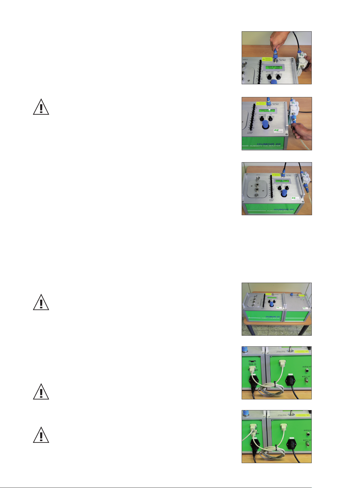
Attach the oil separator / filter set to the side of HUMOR 20, on the
bracket, and establish a connection to the input "Pressure in".
Connect the pressurised (min. 8 bar) compressed air line to the filter set.
A supply pressure less than 8 bar can cause leakage at the filter set.
(p ≤10 bar - see safety instructions)
HUMOR 20 is ready for operation.
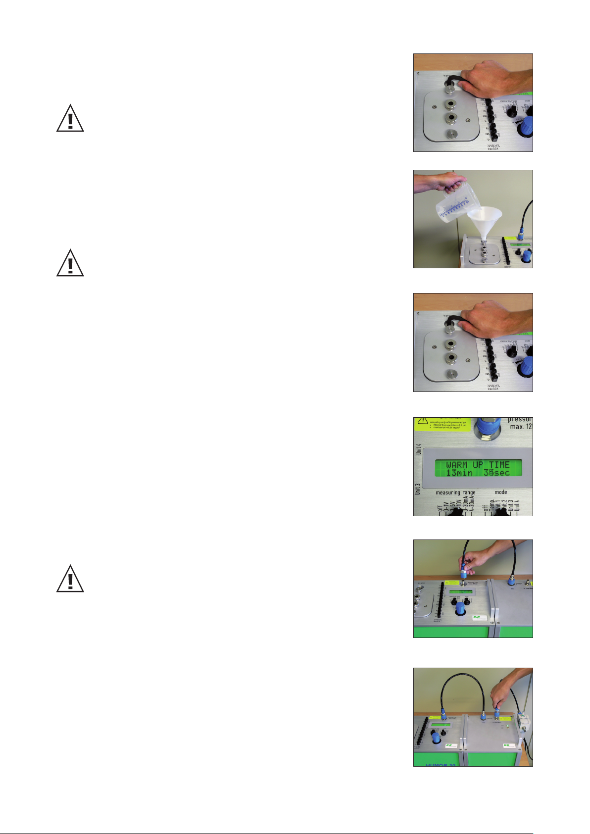
6.3 Starting up HUMOR 20 with automatic calibration module
Setting up HUMOR 20 with the automatic calibration module.
HUMOR 20 must acclimatise at least 6 hours on-site at the calibration location.
Establish a serial connection between HUMOR 20 and the automatic
calibration module. Connect "RS232-Humor" on the automatic calibration module with "RS232" on HUMOR 20.
(Max. cable length allowed is 3m. The length of the supplied cable is
1.8m)
Connect the power cable to a grounded power outlet, but do not switch
on the devices yet, using the main switch!
Establish a serial connection between the automatic calibration module and the PC/notebook.
First switch on HUMOR 20 using the main switch and then the automatic calibration module.
9
Page 10
Open the water tank. Ignore the warm-up time.
Use the Allen key supplied to open the screw plug.
Before opening the water tank, make sure that the humidity calibrator
is no longer under pressure. Turn the humidity controller to the left
(anti-clockwise) as far as it will go and wait until "RH > 90%" is shown
in the display of HUMOR 20.
Fill HUMOR 20 with distilled water.
Fill the humidity calibrator with max. 1,300 ml distilled (deionised)
water.
If the maximum level is exceeded, the warning WATERLEVEL HIGH is
shown in the display. If this happens, drain water until the warning
disappears (see section "9.2 Drain water").
During the filling process, make sure that no water enters the measuring chamber.
Close the water tank.
Use the Allen key supplied to tighten the screw plug.
Wait until the warm-up phase is completed.
The warm-up phase will take 20 minutes (display: WARM UP TIME).
Establish a compressed-air connection between HUMOR 20 and the
automatic calibration module.
Max. allowed hose length is 1m.
Attach the oil separator to the side of the automatic calibration module,
on the bracket, and establish a connection to the input "Pressure in".
10
Page 11
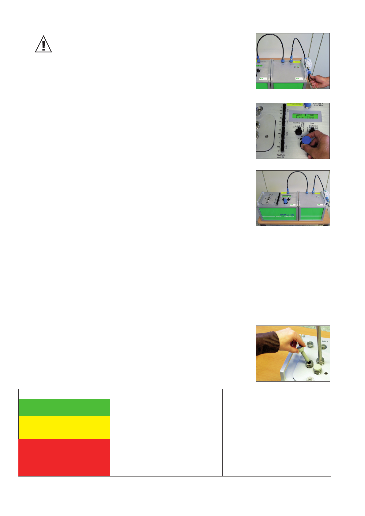
Connect the pressure supply (oil-free compressed air or N2).
A supply pressure less than 8 bar can cause leakage at the filter set.
(p ≤10 bar - see safety instructions)
Turn the humidity controller to the right (clockwise) as far as it will
go.
HUMOR 20 with the automatic calibration module is ready for
operation.
6.4 Verifying the 100%RH Point
To obtain the highest accuracy of the humidity measurement it is
recommended to verify the 100 %RH point every 4 weeks during continues operation or each time before putting the Humor 20 into operation.
The verification has to be executed as follows:
• Turn the humidity controller counterclockwise all the way
• Disconnect the air pressure supply to the Humor
• Display reading > 95 %RH
• Open the water inlet
• Open the measuring chamber (one opening is sufficient,
see picture)
• Read the display after approx. 5 minutes:
Display reading Final conclusion on performance Required action
99.2% to 100.8%
97.0% to 99.2% and 100.8%
to 103.0%
< 97.0% and >103.0%
HUMOR within specifications A high accurate measurement can be
realized
HUMOR outside specifications Adjustment is necessary to obtain the
highest accuracy (see chapter "8.3.2.
Calibration").
HUMOR outside specifications Adjustment is not possible. There is a
problem with the humidity measurement / indication and the HUMOR
should be returned to E+E Elektronik
for calibration / repair.
11
Page 12

7. CALIBRATION AND ADJUSTMENT PROCEDURE
TERMINOLOGY:
Calibration = verification / checking
Adjustment = modification / tuning
The special design of the measuring chamber allows the calibration and adjustment of transmitters
of varying sizes. These include cylindrical sensor probes with a diameter of 8-25.5 mm (0.3-1")
(hand-held instruments, duct-mounted versions, ...) and room transmitters, data loggers, etc. with
maximum dimensions of 100 x 85 x 40 mm (3.9x3.3x1.6") or 95 x 95 x 40 mm (3.7x3.7x1.6").
7.1 Cubical transmitters (room design) with HUMOR 20
HUMOR 20 can also be used to calibrate and adjust room devices
using the Plexiglas cover for the measuring chamber provided in the
scope of supply.
Due to external thermal interference, additional measuring errors may
occur depending on the adjusted humidity and the position of the test
unit in the measuring chamber.
1. Place the test unit in the measuring chamber.
2. Lay the O-ring for the Plexiglas cover in the groove provided in the measuring chamber.
3. Feed the connection cable through the PG screw connection of the Plexiglas cover.
4. Fit the cover and tighten both knurled nuts.
5. Connect the test unit to the supply connections of HUMOR 20.
6. Connect the output signal of the test unit to the internal measuring inputs of
HUMOR 20 (Unit1 RH, Unit2 RH)
7. Select the measuring range in accordance with the output signal of the test unit.
The temperature of the measuring chamber can be displayed by selecting
"Temp." on the measuring range switch.
8.
manufacturer's documentation (however, a minimum of 20 mins is recommended).
9. Use the controller to select the setpoint of the humidity.
10. Compare the values shown in the display with the output signal of the transmitter.
For information on the standard deviations and stabilisation times of the test unit, refer to the
7.2 Transmitter with sensor probe with HUMOR 20
Because of the operating principle, HUMOR 20 has a slightly higher
temperature than ambient. During the measurement process, make
sure that the probe temperature can adapt to the temperature of the
measuring chamber.
To ensure accurate measurements, the cover feedthrough must match
the probe diameter as closely as possible. To ensure that this is the
case, various cover designs are available (see the accessories appendix).
1. Fit a suitable measuring chamber cover (note the position and diameter of
the feedthrough) and tighten both knurled nuts.
If inserted, remove the O-ring for the Plexiglas cover.
2. Insert the test unit(s) through the feedthrough(s) in the measuring chamber and tighten the
screw connection(s).
If using the modules EE07 and EE08 (with cables) please note that only the filter caps get
into the measuring chamber of the HUMOR to avoid falsification of the calibration through self
heating effects (see picture on the left).
12
Page 13

3. Seal the openings of the feedthroughs not in use with the
supplied plugs.
4. Connect the test unit(s) to the supply connections of HUMOR 20 (24V DC).
Make sure that the total power consumption of all transmitters is
not more than 200 mA. In case the transmitters exceed this
maximum, an external power supply has to be provided.
5. Connect the output signal of the test unit(s) to the internal
measuring inputs of HUMOR 20 (Unit1 RH, Unit2 RH, Unit3 RH,
Unit4 RH).
6. Select the measuring ranges in accordance with the output signal of the test units.
The temperature of the measuring chamber can be displayed by selecting
"Temp." on the measuring range switch.
7. Use the humidity controller to select the setpoint of the humidity.
8. For information on the standard deviations and stabilisation times of the test unit, refer to
the manufacturer's documentation (however, a minimum of 20 mins is recommended).
9. Compare the values shown in the display with the output signal of the transmitter.
7.3 Transmitter EE33 Model J with HUMOR 20
To be able to calibrate the transmitter of the series EE33-MFTJ, with the dual probes (Td-probe and
T–probe), a separate available adapter is needed (see chapter 12 ‘accessories’ – adapter for EE33
– model J, part number HA020401) to achieve the highest possible calibration result. The following
steps describe how the series EE33-MFTJ should be calibrated correctly.
1. Plug both air vents of the cover of the measurement chamber with the
plugs supplied with the adapter (see left picture).
2. Insert the Td-probe (Ø12mm) in the measuring chamber through one
of the feed-throughs of the cover and tighten the nut.
3. Insert and tighten the T-probe (Ø6mm) in the adapter and insert in the
measuring chamber through one of the feed-throughs of the cover and
tighten the nut.
4. In case that feed-throughs are not in use, close them with the blind plugs delivered with the cover.
Transmitters delivered after June 2009 have the possibility to heat the
tube of the probe continuously to avoid condensation. This function
must be disabled prior to calibration, by detaching the cover of the
transmitter and removing the “heat”-jumper in the left top corner of the
PCB (see left picture).
5. Connect the test unit to the supply connections of HUMOR 20.
6. Connect the output signal of the test unit(s) to the internal measuring
inputs of HUMOR 20 (Unit1 RH, Unit2 RH).
7. Select the measuring ranges in accordance with the output signal of the test units. The
temperature of the measuring chamber can be displayed by selecting "Temp." on the measuring
range switch.
8. Use the humidity controller to select the setpoint of the humidity.
9. For information on the standard deviations and stabilisation times of the test unit, refer to the
manufacturer's documentation (however, a minimum of 20 mins is recommended).
10. Compare the values shown in the display with the output signal of the transmitter.
After calibration, make sure that the plugs in the air vents in the cover of the measuring chamber are
removed.
13
Page 14

7.4 Analogue Output HUMOR 20
On the back panel of the HUMOR 20 sits a 4-pole
connector with the label “analog out”.
Here are the conditions of the measuring chamber
(RH, T) reproduced in the form of an analog signal.
Plug Connection:
Contact-Nr Signal Scaling
1 GND
2 not connected
3 RH_out 0-10V = 0-100% RH
4 T_out 0-10V = 0-50°C
7.5 Calibration with the automatic calibration module
see section “8.4 Measurements”.
7.6 Power failure during the calibration procedure
HUMOR 20
In the event of longer power failures (> 5min.), unlock (pull out) the controller's
rotary knob and turn it anticlockwise as far as it will go. Disconnect the media
supply. Once the power returns and the warm up phase has been completed, the calibration process
can be resumed.
HUMOR 20 with the automatic calibration module
In the event of a power failure, an error message is displayed (see screenshot) and the calibration
must be restarted.
7.7 Ending the calibration or adjustment procedure
If longer idle periods are expected, it is recommended to empty the distilled (deionised) water tank
completely.
For more information, see section "9.2 Drain water".
Remove the supply pressure (compressed air) and turn off the main switch (if applicable, disconnect
the grounding plug).
14
Page 15

8. HUMOR 20 SOFTWARE
This software was developed by E+E Elektronik® in order to adapt the humidity calibrator HUMOR
20 to customer requirements, to log measured values, and to register the data in an adjustable
measurement protocol.
8.1 Installation the software
1. Insert the CD-ROM supplied into your PC drive.
2. Close all other active programs.
3. Double-click on the file "Setup.exe".
4. Follow the instructions in the context menu.
Once HUMOR 20 is connected to the PC via the serial interface and the software is started, the
alongside input windows appear.
Procedure:
1. Select language.
2. Select the COM Port. Changes can be made at any time
in the menu under "Operation" - "Select COM Port".
3. Start screen:
Menu bar
Buttons to switch the
control panels for the
various operating
modes
Control panel
On starting the software, the configuration modes starts automatically and the serial numbers and
status of HUMOR 20 and the automatic calibration module are loaded.
15
Page 16

8.2 Configuration mode control panel
The serial
numbers and
status of
HUMOR 20
and the automatic calibra-
Status of the calibration mode
Status of the temperature unit °C or °F
tion module
are loaded.
8.3 Menu bar
8.3.1 Operation
The pull-down menu "Operation" includes all the functions required to configure the humidity
calibrator in accordance with customer requirements and to exit the program.
Abort warm up time:
Aborts the warm up phase (20 mins).
The warm up phase is essential in order to achieve very accurate
measuring results.
Toggle calibration mode:
The humidity calibrator has 2 calibration modes. Users can switch between factory calibration and
customer calibration.
The current calibration mode is shown in the start menu of the software and in the display of the
humidity calibrator.
"F" (Factory)
"C" (Customer)
Toggle temperature unit:
The temperature is set to SI or U.S. engineering units for the temperature to be displayed in degrees Fahrenheit or degrees
Celsius.
16
Page 17

Design protocol:
In addition, the HUMOR 20 software provides the option of automatically generating a measurement protocol.
A ready-made template is defined and on completion of themeasurement filled out automatically with the calculated values.
Immediately after the end of the measurement process, a protocol
in a well-organised format can be generated at the touch of a
button.
E+E Elektronik offers a ready-made standard
template that opens automatically on selection of
the function "Design protocol". This standard
template can easily be altered to meet customer
requirements.
To create a fully customer-specific layout for the
measurement protocol, the help text for the protocol designer has to be read carefully because of
the wide range of options and functions.
Therefore, the following approach is recommended:
To minimize the effort to create the form /
protocol, just change the text fields or logo of the
standard template only.
To do so, choose "Save as" from the menu and
save the standard protocol under a new file name
of your choice.
To make sure that the standard template will no be
changed, open the protocol designer again and
choose the file just created and change it as
desired.
Changing the logo:
To enter your own logo in the protocol, select the
placeholder (arrow 1). Your logo can be integrated
in the protocol template by clicking on the specified
path in the menu "Properties-Data-Source-File
Name" (arrow 2).
1)
17
2)
Page 18

Changing text fields:
To change text in the measurement protocol,
choose the required text field (arrow 1) and click on
the icon in the menu
"Properties - Data - Contents" (arrow 2).
You can change the text and format as desired in
the pop-up window "Paragraph Properties" (arrow 3).
In this way, you can easily substitute the German
text for textin the relevant language.
3)
New protocol template:
If you would like to create a complete new protocol
template, refer to the information in the protocol
designer's help text.
If you have any questions, pleased contact the E+E
Elektronik customer service team directly.
2)
1)
18
Page 19

To simplify the design of your own measurement protocol, the list below provides an overview of the
most important variables and fields as well as their content.
Variables: Contents can be incorporated directly into the form design.
Fields: Contents of fields can in addition be incorporated in every row of a table
dependent on the number of measurement points (dynamic).
Variables: Their content can be added directly into measurement protocols.
Candidate 1:
Calibration number
Connection port
Customer
Manufacturer
Name
Output signal
Output analogue or manual
Serial number
Type
Candidate 2, 3, 4:
Output signal
Serial number
Type
Number of measurement points
Company: customer-specific data can be assigned with the following variables:
City
Country
E-mail
Fax
Contact person
Telephone
Street
Street 2
Internet address
Postcode
Humor: the used HUMOR is described with the following variables
Current operating state (Customer - / Factory Calibration)
Type of device
Firmware version
Serial number of device
Serial number of integrated electronics
Used temperature unit °C / °F
List of warnings and error messages
19
Page 20

Fields: Their content can be inserted in dynamic tables of the measurement protocol
Candidate 1:
Calibration number
Connection port
Custormer
Manufacturer
Name
Output signal
Output analogue or manual
Serial number
Type
Candidate 2, 3, 4:
Output signal
Serial number
Type
Configuration:
Number of measuring points
max. deviation RH (can be set)
RH (setpoint)
Stabilisation time (setpoint)
Humor: the used HUMOR is described with the following variables
Current operating state (Customer - / Factory Calibration)
Serial number of device
Serial number of integrated electronics
used temperature unit
List of warnings and error messages
Determined measured values per measurement point:
Measurement result candidate
End of the stabilization time
Start of the stabilization time
Deviation of the candidate to the Humidity - reference value of the HUMOR 20
Humidity - reference value - HUMOR 20
Temperature - measured value HUMOR 20
Stabilization time
20
Page 21

Print protocol:
On completion of the measurement process, the measured
values can be printed in a protocol.
Use the command "Open" to choose between two
pre-installed protocols.
If you have created your own protocol, this can also be
selected here.
Export measurement data:
You can export the measurement data to Microsoft Excel
Select COM port:
You can use this function to change the COM port.
.
®
.
Exit:
The program is closed.
21
Page 22

8.3.2 Adjustment / Calibration
Temperature calibration:
Only possible in the "CUSTOMER calibration" mode.
The temperature is equalised with a temperature standard.
A stabilisation time of 2h is recommended.
1. Insert an external temperature standard into the measuring
chamber.
2. Enter the reference value in the input field.
Important: Temperature must be within the range 23°C ± 10°C.
3. With "Store" the adjusted temperature value is implemented.
Monitoring sensor calibration:
Only possible in the "CUSTOMER calibration" mode.
This function can be used to adjust 2 points of the humidity transmitter integrated in HUMOR 20 for monitoring purposes.
Procedure:
1. Acclimatise HUMOR 20 to the ambient conditions
(temperature homogeneity).
2. HUMOR 20 should run for an additional 2 hours after the
warm up phase.
3. Set the lower setpoint to 30% RH.
4. Once the stabilisation time has expired (30 mins), equalise the
"Monitoring Sensor" to the reference value of HUMOR 20.
5. Set the upper setpoint to 70% RH.
6. Once the stabilisation time has expired (30 mins), equalise the
"Monitoring Sensor" to the reference value of HUMOR 20.
Analog Measurement Input Calibration:
With this function, the analog measurement inputs of the Humor20
(1-4) can be checked:
1. Select with Switch1 (see 6.1) either a current or a voltage
range.
2. Select with Switch 2 (see 6.1) the measurement input to be
tested.
3. Connect the external signal source with the selected Humor20
measurement input (1-4).
4. Set the analogue signal from the external source (0 – 10 V or
0 – 20 mA)
5. In the display the measured value will be indicated.
22
Page 23

Reset to Factory settings:
All of the adjustment's calibration data is reset to the factory
calibration default values.
8.3.3 Pressure Compensation
This function is used to equalise the two pressure transmitters
of HUMOR 20.
For accurate measurements, the equalisation should be
performedevery 4 weeks.
Follow the instructions in the info field and
press the button "Store".
Once the equalisation is complete, check that "
100% RH" is shown in the HUMOR 20 display.
Mode of operation:
The offset of the absolute pressure transmitter in the saturation chamber P
P2 = P
Reference
in the measuring chamber.
(0-10 bar) is aligned to
1
Transmitters P1 and P2 are now aligned to the atmospheric pressure. A alignment has been
performed at 100% RH.
23
Page 24

8.4 Measurements
8.4.1 Start screen
"Test units"
configuration field
"Measurements"
configuration field
Info field
8.4.2 "Test unit" configuration field
Enter the number of test units to be measured in the "Test unit count" field and confirm your
e"configuration for each test unit.
Output:
Here you choose how the test unit's measured value should be
entered:
Manual input: Once the stabilisation time has expired, the
measuring program waits until the measured value is entered
manually. Press "Set" to confirm your entry.
Analogue (Humor20): Once the stabilisation time has expired,
the measured value is adopted automatically by the measuring input of HUMOR 20.
Range/Prot.:
[Only active with the "Analogue (Humor20)" output]
Here, you select what the output signal of the test unit is.
Unit/Port:
[Only active with the "Analogue (Humor20)" output]
Select the measuring input (Unit 1 - Unit 4) used to connect the test
unit to HUMOR 20.
Note: the rotary knob of the HUMOR 20 has to be set at the correct
measurement input as well, to indicate desired measurement value
in the display.
24
Page 25

Test unit / Ser.No / Type / Make / Customer / Cal.No:
Test unit:
Enter the type designation of the test unit here.
This field can be included in the protocol.
Ser.No:
Enter the serial number of the test unit here.
This field can be included in the protocol.
Type:
Enter the type of the test unit here.
This field can be included in the protocol.
Make:
Enter the make of the test unit here.
This field can be included in the protocol.
Customer:
Enter the name of the customer here.
This field can be included in the protocol.
Cal.No:
Enter the calibration number (your internal number) for the job.
This field can be included in the protocol.
You can save the configuration for the test unit(s) by pressing the "Store Config." button.
To load a stored configuration, choose "Load Config.".
25
Page 26

8.4.3 "Measurements" configuration field
Measurement points count:
Enter the number of measurement points and confirm your entry by pressing "Apply".
Set measured values automatically:
Checkbox selected: The test unit's measured value at the measuring input of HUMOR 20 is set automatically once the stabilisation time has expired.
Checkbox not selected: The program waits for the measured value to be entered manually once the
stabilisation time has expired.
Log measured values additionally in
fixed interval:
If you select this checkbox, the test unit's
measured values will be logged by the
measuring input of HUMOR 20.
The measured values are stored in the file
"MeasLog.csv" in the program directory of
the HUMOR 20 software.
Now you can set the measurement points:
Target RH:
Enter the humidity value of the measurement point, e.g. 20 for 20% RH.
Target time [min]:
Enter the required stabilisation time in minutes (e.g. 20 for 00h 20min or 80 for 01h 20min).
Spec. dev. RH:
Enter the permitted tolerance for the measurement point. You can only enter numerical values (e.g.
2 for ±2% RH).
Once all the measurement points have been fully configured, you can start the measurement by
pressing the "Start" button.
If using an automatic calibration module, turn the humidity controller to the right (clockwise) as far
as it will go, refer to chapter 6.3.
The automatic calibration module now
adjusts to the first measurement point.
During this adjustment procedure, the
orange LED "auto" on the automatic calibration module flashes. Once the setpoint
has been reached, the LED lights up continuously.
If the measurement point is reached within
a range of ±1% RH, the stabilisation time
for the measurement point begins to run.
Once the stabilisation time has expired,
depending on whether the checkbox "Set
measured values automatically" has been selected, either the system enters the value of the measuring input of HUMOR 20 or waits for a manual entry.
Once the measurement is completed, the automatic calibration module adjusts the humidity to 10%
RH (orange "auto" LED goes out). The measured values are stored in the program directory
[.....\E+E Elektronik\HUMOR-20\MeasData].
The file name consist of the current date and time e.g. 2008-08-25_12_10_05.hmf
Note: If the measurement is aborted, no measured values are stored!
26
Page 27

8.5 Fixed RH Value (only available when using an automatic calibration
module)
The humidity control knob of the Humor20 has to be turned to the right (clockwise) all the way to the
stop, see chapter 6.3
Start Button:
as soon as the desired value is entered and the
"Start-Button” is pressed, the desired humidity in the
measurement chamber will be set by the Automatic
Calibration Module (orange “auto” LED blinks or illuminates)
Stop-Button:
activating the “Stop-Button” will end the control of the
Automatic Calibration Module (orange “auto”
LED not illuminated); in this way, a humidity level of 10 %RH will be set in the measuring
chamber of the Humor20.
9. MAINTENANCE
The distilled (deionised) water should be changed every 8 weeks.
If the unit is idle for longer periods, all the water should be removed.
9.1 Re-fill water (at error message - waterlevel low)
1. Turn the humidity controller all the way to the left and wait until the
message "OUT OF SPEC" is displayed.
2. Remove the screw plug.
3. Fill with distilled (deionised) water (when the error message
"Waterlevel low" is displayed, a max. of 1,000 ml can be added).
4. Replace the screw plug and tighten.
5. If the maximum fill level is exceeded, the error message "Waterlevel high" is displayed, and
water must be removed until the message on the display disappears.
6. After filling, wait for a stabilisation time of around 20 mins (the higher the difference in
temperature between the water and the humidity calibrator, the longer the stabilisation time
ought to be).
7. HUMOR 20 is ready for operation.
9.2 Drain water (at error message - waterlevel high or long idle periods)
1. Turn the humidity controller all the way to the left and wait until the
message rel.HUM high appears in the display.
2. If you are using the automatic calibration module, connect the
compressed air supply directly to HUMOR 20.
3. Connect the water drain hose to the discharge nozzle.
4. Turn the humidity controller slowly to the right until water drains
out.
a) Until the "Waterlevel high" message disappears.
b) Until the saturation chamber is completely empty. To make
sure that the chamber is completely dry, flow air through the
device for a short time.
5. To end the drainage process, turn the humidity controller to the
left again as far as it will go.
6. Disconnect the compressed air and the water drain hose.
7. HUMOR 20 can now be turned off.
9.3 Cleaning
For cleaning the HUMOR20 and automatic calibration module a dry drapery should be used.
27
Page 28

10. WARNINGS / ERROR MESSAGES ON THE DISPLAY
rel. HUM. =100.0%
WATERLEVEL LOW
rel. HUM. =100.0%
rel. HUM. =100.0%
WATERLEVEL LOW
1st line: Displays moisture () or error ()
2nd line: Status bar () and actual value of the test unit on HUMOR 20
The humidity calibrator is equipped with an auto diagnostic system. It issues different operating or
error messages depending on the operating status or error. You can remedy the cause of the messages as follows:
CAUSE REMEDY
10.1 Humidity - display flashes
1. After a sudden change in the setpoint, the
measuring chamber has not reached the
desired value immediately. As soon as the difference between the relative humidity shown in
the measuring chamber and the setpoint
exceeds a defined range, the display starts to
flash.
2. Water in the measuring chamber or internal
lines.
This error is usually caused by transporting a
HUMOR 20 device filled with water or connecting compressed air when the humidity controller has not been turned all the way to the left.
Wait for the stabilisation time to end (after a few
minutes, the display should stop flashing automatically).
Dry the measuring chamber with an absorbent
cloth. Drain the water, and let compressed air or
nitrogen flow through the device for a lengthy
period. This is achieved by specifying a
setpoint of 75% on the humidity controller.
During the purging (drying), the display flashes
and the warning WATERLEVEL LOW is shown.
The drying process lasts around 48h and
should be monitored by a test unit. The drying
process is complete as soon as the test unit
shows a relative humidity of < 15%.
This process can be accelerated by using dry
compressed air or dry nitrogen.
10.2 Warning: OUT OF SPEC
A humidity setpoint > 95% RH was specified or
< 10% RH was selected.
10.3 Warning: WATERLEVEL HIGH
The maximum fill level for distilled (deionised)
water has been exceeded.
28
Device is operated outside of the working
range.
Empty water until the warning disappears.
Page 29

10.4 Warning: WATERLEVEL LOW
The water level is below its minimum. Add distilled (deionised) water.
10.5 Error message: heat defect
HUMOR 20 has not reached its operating
temperature.
10.6 Error message: pressure excess
A humidity setpoint < 8% RH was selected. The
humidity calibrator may have been damaged by
the high pressure. The specified accuracy
cannot longer be guaranteed.
10.7 Humidity - display is incorrect
Incorrect display, e.g. because of an error in the
electronics.
10.8 Stabilisation time too long
Valve defect.
Contact your E+E Elektronik sales partner.
Contact your E+E Elektronik sales partner.
Check HUMOR 20.
Turn the controller to the left as far as it will go
and disconnect the compressed air. After a stabilisation time of 2h, the display should show
100 ±2%RH. If this is not the case, contact your
E+E Elektronik sales partner.
Check the flow.
1. Drain all the water completely and refill the
humidity calibrator with exactly 1000 ml of distilled water.
2. Specify a humidity setpoint of exactly 20% RH.
3. Turn the humidity controller all the way to
the left and measure the time it takes for the
value 80%RH to appear in the display.
- If the time measured is < 80sec, the
flow is correct and within the working
range.
- If the process takes much longer, contact
your E+E Elektronik sales partner.
The response time of HUMOR 20 for a jump in
humidity from 25 to 80% RH and from 80 to 25% RH
is shown in the graph. A jump to a lower value requires
approx. 1 minute, while a jump to a higher humidity
value requires approx. 3 minutes.
The required stabilisation time is determined primarily
by the test unit.
Considering the response times of instruments now
available on the market (equipped with standard
filters),
a stabilisation time of approx.20 minutes /
measurement point can be expected.
29
Relative humidity [%RH]
Time [min]
Page 30

10.9 Leakage in filter set
CAUSE REMEDY
You will hear if there is a leakage in the filter set
(escaping air).
Disconnect the compressed air supply
and check the pressure.
Make sure the supply is at least 8 bar. Reconnect
the pressure supply.
10.10 Electronic defect - replace electronics
Replacing the electronics:
1. Disconnect the humidity calibrator from the supply voltage.
2. Loosen the screws (see Fig. 1).
3. Loosen the recessed-head screws on the 19" rack (see Fig. 2).
4. Pull out the plug-in module (electronics) (see Fig. 3).
5. Insert the replacement electronics and close the housing.
6. Calibrate HUMOR 20.
The factory calibration is lost when the electronics are replaced!
If you have any questions, please contact your E+E Elektronik sales partner.
Fig. 1
10.11 Fuse defect - Replacing the fuse (Humor20 + Autokit)
Replacing the fuse:
1. Disconnect the humidity calibrator from supply voltage.
2. Open bracket (see Fig. 1).
3. Remove fuse (see Fig. 2).
4. Insert new fuse (Type: 6,3x32mm F1: 1A 250V T (slow)
- Note the arrow direction (see Fig. 3).
5. Close bracket.
6. Calibrate HUMOR 20.
If you have any questions, please contact your E+E Elektronik sales
partner.
Fig. 2
Fig. 3
Fig. 1
30
Fig. 2
Fig. 3
Page 31

11. TECHNICAL DATA
General
Function principle two-pressure-reactor
Working range 10...95% RH
Protection class I
Protection type IP40
Surge voltage category II
Installation altitude up to 2000 m above sea level
Application Indoors
Accuracy of measurement
Accuracy temperature measure-
ment in measuring chambe
Power supply 100...230V AC, 50/60Hz, max. 20W
Work equipment • compressed air, filtered and free of oil or nitrogen N2 with max. 10bar (145psi)
• distilled water
Stabilisation time HUMOR 20 < 3 min/measuring point
Stabilisation time specimen typ. 20 min/Messpunkt
Integrated power supply 24V DC, max. 200mA
Number of measuring inputs 4 (switchable between 4...20mA / 0...20mA / 0...1V / 0...5V / 0...10V)
Typ. error for display inputs Voltage measuring: < 5mV
Current measuring: < 30µA
Display Dot-matrix display with backlight
Gas flow 3 l/min or RH > 85% the gas flow is reduced to 1.5 l/min at 95% RH
Recommended interval for 1 year
recalibration
Interface for PC connection RS232 (COM-Port)
System requirements for software tools MS Windows 2000 mit SP 2 / Windows XP / Windows Vista
Environmental conditions temperature: 10...40°C (50...104°F)
humidity: 10...80% RH
CE conformity EN61000-6-3:2007 EN61326-1:2006
EN61000-6-2:2006 EN61010-1:2010
Additional Standards EN60068-2-6 EN60068-2-29
Dimensions 400 x 260 x 240 mm (15.7 x 10.2 x 9.4”)
Weight HUMOR 20: about 23kg (51 lbs)
HUMOR 20 incl. aluminium transport case: about 36.5kg (80.5 lbs)
Measuring Chamber
The construction of the measuring chamber allows the calibration and adjustment of cylindrical sensor
probes with a diameter of 8-25.5mm (0.3-1”) (hand-held instruments, duct-mounted versions, ...) as well
as of cubic measuring units (room transmitters, data loggers, ...) with maximum dimensions of
100x85x40mm
By using the Plexiglas cover (standard supply), it is possible to calibrate and adjust compact room devices
(e.g., the EE10) with the HUMOR 20.
The overall accuracy of the calibration is influenced by the absence of the metal cover. The additional error
depends on the position of the specimen in the chamber as well as on the relative humidity.
(3.9x3.3x1.6”) or 95x95x40mm (3.9x3.9x1.6”).
1) 2)
u(Uw) [% RH] (k=2)
2)
typ. ±0.3°C (±0.54°F)
relative humidity Uw [% RH]
1) The extended inaccuracy of measurement results from the standard inaccuracy increased by a multiplying factor of K=2.
2) Valid for metal covers for the measuring chambers
31
Page 32

12. ACCESSORIES
12.1 Oil-free compressor
Technical Data:
Max. operation pressure
Supply voltage
Noise level
Dimensions (l x w x h)
Weight
12.2 Covers for measuring chamber
(174psi)
12bar
230V AC // 50 or 60Hz
57 dB(A)/lm
410 x 410 x 500 mm
(46lbs)
21kg
(16 x 16 x 20“)
Various covers for the measuring chamber accommodate probes of all diameters available on the market.
With these covers up to four probes can
be calibrated simultaneously.
SUITABLE FOR NUMBER OF
Humor cover 12 - 16mm
Humor cover 16 - 20.5mm
Humor cover 20.5 - 25.5mm
Humor cover 8 - 12mm
Humor cover 12 - 13mm
Humor cover für HUMLOG 10
Humor cover 12 - 16mm
Humor cover 16 - 20.5mm
Humor cover 30mm
Adapter for EE33 - modell J
1) only useable in combination with HA020204 or HA020201
(0.5 - 0.6”) plane for 2 Probes
(0.6 - 0.8”) plane for 1 Probe
(0.8 - 1”) plane for 1 Probe
(0.3 - 0.5”) plane for 3 Probes
(0,5 - 0,52”) conic
(0.5 - 0.6”) bevelled
(0.6 - 0.8”) bevelled
(1,2”) plane
1)
12.3 Calibration certificate
To meet the requirements of Quality Management Systems such as
ISO9001 regarding calibration and certification of measurement and
test instrumentation, the HUMOR 20 is available with an official OEKD
accredited calibration certificate.
FEEDTHROUGHS
for 4 Probes
for 1 Probe
for 4 Probes
for 4 Probes
for 1 Probe
ORDER-
CODE
HA020201
HA020202
HA020203
HA020204
HA020205
HA020206
HA020207
HA020208
HA020409
HA020401
12.4 Automatic calibration module
For the fully automatic measurement of the characteristics of a transmitter.
Technical Data:
Weight
Dimensions
Supply
Interface to PC RS232 (COM Port)
Compressed air supply
Protection type IP40
Protection class I
Pollutional index 2
Surge voltage category II
Installation altitude up to 2000 m above sea level
Application Indoors
CE conformity
Additional Standards EN60068-2-6 EN60068-2-29
- weight of instrument: 9kg (20lbs)
- instrument incl. aluminium transport case: 23kg (51lbs)
260x260x240mm (LxBxH);
100...230V AC, 50/60 Hz max. 15W
min. 9.8bar
filtered oil-free compressed air, max. size of particle: 5μm
EN61000-6-3:2007 EN61326-1:2006
EN61000-6-2:2006 EN61010-1:2010
(142psi); max. 12bar (174bar);
(10.2”x10.2”x9.4”)
32
Page 33

333435
Page 34

Page 35

Page 36

HEAD OFFICE:
E+E ELEKTRONIK Ges.m.b.H.
Langwiesen 7
A-4209 Engerwitzdorf
Austria
Tel: +43 7235 605 0
Fax: +43 7235 605 8
info@epluse.com
www.epluse.com
SALES OFFICES:
E+E CHINA / BEIJING
Tel: +86 10 84992361
info@epluse.cn www.epluse.cn
E+E CHINA / SHANGHAI
Tel: +86 21 61176129
info@epluse.cn www.epluse.cn
E+E GERMANY
Tel: +49 6172 13881 0
info@epluse.de www.epluse.de
E+E FRANCE
Tel: +33 4 7472 35 82
info@epluse.fr www.epluse.fr
E+E ITALY
Tel: +39 02 2707 8636
info@epluse.it www.epluse.it
E+E KOREA
Tel: +82 31 732 6050
info@epluse.co.kr www.epluse.co.kr
E+E USA
Tel: +1 508 530 3068
office@epluse.com www.epluse.com
 Loading...